NATBR433BPLow Power RF Reciever for Tire pressure monitoring
Bendix Commercial Vehicle Systems LLC
Click to zoom
Application Details
- Equipment Class
- CYY - Communications Receiver used w/Pt 15 Transmitter
- Date of Grant
- Jun 28, 2000
- Application Purpose
- Original Equipment
- Date of Application
- Jun 04, 2000
- Equipment Note
- Low Power RF Reciever for Tire pressure monitoring
- Frequency Range
- 433.30000000 - 433.30000000
- Country
- Canada
Documents & Files
Document Text
Text extracted from the exhibit documents filed with the FCC. Open a document above to read the original.
Users Manual
SmarTire Systems Inc. Tire Monitoring System Reference Manual 6/20/2000 Page 1 of 56 This manual is under review by SmarTire – DO NOT ISSUE Draft Tire Monitor System Reference Manual GENII Draft Note; Prior to issue this manual to be examined and approved by; Engineering Marketing Customer Service SmarTire Systems Inc. Tire Monitoring System Reference Manual 6/20/2000 Page 2 of 56 This manual is under review by SmarTire – DO NOT ISSUE Table of Contents FCC Notice...................................................................................................................................5 Introduction.................................................................................................................................6 Purpose of Manual....................................................................................................................6 About Tire Monitoring Systems..............................................................................................6 Feature Summary..................................................................................................................................................................7 System Scope of Use and Warnings........................................................................................8 The SmarTire™ System and Tire Maintenance..............................................................................................................8 System Installation and Usage............................................................................................................................................8 Use of Chemicals..................................................................................................................................................................8 Power Connection.................................................................................................................................................................8 Warnings.................................................................................................................................................................................8 SmarTire Product Overview..................................................................................................10 Product List.............................................................................................................................10 Tire Monitor System Kit Component Table........................................................................11 System Descriptions................................................................................................................12 Pressure Alert Systems – 2 and 4 wheels – Multi-fit Strap Mount Transmitters.....................................................12 Overview.........................................................................................................................................................................12 Bill of Materials.............................................................................................................................................................13 Component Images........................................................................................................................................................14 Pressure Alert Systems – 2 and 4 wheels – Multi-fit Valve Mount Transmitters....................................................15 Overview.........................................................................................................................................................................15 Bill of Materials.............................................................................................................................................................16 Component Images........................................................................................................................................................17 Pressure Alert Full Function Display...............................................................................................................................18 Overview.........................................................................................................................................................................18 Bill of Materials.............................................................................................................................................................19 Component Images........................................................................................................................................................19 Pressure Alert Flexible Power Adaptor...........................................................................................................................20 Overview.........................................................................................................................................................................20 Bill of Materials.............................................................................................................................................................20 Component Image..........................................................................................................................................................20 Pressure Alert Transmitter Kit – 2 - Multi-fit Strap Mount Transmitters.................................................................21 Overview.........................................................................................................................................................................21 Bill of Materials.............................................................................................................................................................21 Component Image................................................................................................…
Text truncated - open the document above for the full version.
Cover Letter(s)
June 2, 2000 Authorization & Evaluation Division Federal Communications Commission Laboratory 7435 Oakland Mills Road Columbia, MD 21046 Subject: Application for Certification of our SuperHetrodyne Receiver, Model 210.0129 with FCC ID: NATBR433BP Attention: Mr. Frank Coperich, Mr. George Tannahill. Dear Sirs: Smartire Systems Inc, of Ri chmond B.C., Canada, herein submits appli cation for Certification of a superheterodyne receiver This receiver was tested in accordance with the requirements contained in the Part 15 of Title 47 CFR. To the best of my knowledge, these tests were performed using the criteria established in ANSI C63.4, 1992 and demonstrates that the equipment compiles with the published standard. The applicable rule sections are listed in the following test report. The Open Area Test Site is registered, with FCC Registration Number 96437. A complete Certification application is enclosed, contact Rob Stirling at (604) 218 1762 for testing detail s, or if you require any information about the submission. Sincerely, Rob Stirling, P.Eng EMAIL [email protected] APPLICATION FOR CERTIFICATION OF A SUPERHETERODYNE RECEIVER UNDER CFR TITLE 47, PART 15.109 GRANTEE:SmarTire Systems, Inc. FCC ID: NATBR433BP June 2, 2000 Prepared By: Protocol Labs 28945 McTavish Rd. Abbotsford B.C., Canada, V4X 2E7 FCC Registration Number 96437 Industry Canada Registration Number IC3384 TABLE OF CONTENTS Letter of Submittal and Compliance, Table of ContentsExhibit 1 Technical Description, Functional Block Diagram of Receiver and General Technical Specifications and Theory of OperationExhibit 2 Owners ManualExhibit 3 Test Report: Field Strength of Radiated Emissions Part 15.109(a) Exhibit 4 Receiver Antenna Power Conduction Part 15.111N/A Photographs of EUT Radiated Emissions SetupExhibit 5 Detailed Photographs of EUT Exhibit 6 a, b and c FCC Identifier Label and LocationExhibit 7 Schematics, Artwork, Drawings and Parts Bill of MaterialsExhibit 8
ID Label/Location Info
THIS INFORMATION IS PROPRIETARY AND MUST NOT BE COPIED AND/OR REVEALED TO THIRD PARTIES WITHOUT THE WRITTEN CONSENT OF SMARTIRE SYSTEMS INC. Title: Drawn C.LIBERA Checked SPECIFICATION: LABEL REGULATORY - Receiver - BASE DWG NO. 269.0123.CS DL-1098 RELREV DESCRIPTIONDATEINIT Designer C.LIBERA Manager S.LAMMERS 2-Feb-00 CLOriginal 0 0 ProtoPilotProduction 2000 SmarTire Systems Inc. #150-13151 Vanier Place, Richmond, British Columbia V6V 2J1 Label position on back of receiver 0.650 in 0.650 in 1/32” CORNER RADIUS 2” STOCK, 2 LABELS ACROSS, SPACE AS SHOWN 0.250 in 0.125 in 2.000 in THIS DEVICE COMPLIES WITH PART 15 OF THE FCC RULES. OPERATION IS SUBJECT TO THE FOLLOWING TWO CONDITIONS: (1) THIS DEVICE MAY NOT CAUSE HARMFUL INTERFERENCE, AND (2) THIS DEVICE MUST ACCEPT ANY INTERFERENCE THAT MAY CAUSE UNDESIRED OPERATION. THIS DEVICE COMPLIES WITH PART 15 OF THE FCC RULES. OPERATION IS SUBJECT TO THE FOLLOWING TWO CONDITIONS: (1) THIS DEVICE MAY NOT CAUSE HARMFUL INTERFERENCE, AND (2) THIS DEVICE MUST ACCEPT ANY INTERFERENCE THAT MAY CAUSE UNDESIRED OPERATION. FCCID-XXXXXXXXXXX FCCID-XXXXXXXXXXX MATERIAL 3M #3871 ADHESIVE #350 Print label as shown above for production See - 1097-Product Identification and Labeling Specification for bar code definition Sample regulatory text THIS INFORMATION IS PROPRIETARY AND MUST NOT BE COPIED AND/OR REVEALED TO THIRD PARTIES WITHOUT THE WRITTEN CONSENT OF SMARTIRE SYSTEMS INC. Title: Drawn C.LIBERA Checked SPECIFICATION: LABEL IDSN- 433 Receiver - BASE DWG NO. 269.0119.CS DL-1099 RELREV DESCRIPTIONDATEINIT Designer C.LIBERA Manager S.LAMMERS 2-Feb-00 CLOriginal 00 ProtoPilotProduction 2000 SmarTire Systems Inc. #150-13151 Vanier Place, Richmond, British Columbia V6V 2J1 0.650 in 0.650 in MATERIAL 3M #3871 ADHESIVE #350 Die dimensions 1/32” CORNER RADIUS 2” STOCK, 1 LABES ACROSS, SPACE AS SHOWN 2.000 in 1.3 in 0.6 in 0.125 in Label position on back of receiver Print label as shown above for production -059 = Product code -0000001 = Serial number See - 1097-Product Identification and Labeling Specification for bar code definition PATENTS 5,231,8725,285,189 5,335,5405,559,484 PATENTS 5,231,8725,285,189 5,335,5405,559,484 SmarTire Systems Inc.. SmarTire Systems Inc. RECEIVER 433.92 MHZ RECEIVER 433.92 MHZ 059-0000001 059-0000001
ID Label/Location Info
THIS INFORMATION IS PROPRIETARY AND MUST NOT BE COPIED AND/OR REVEALED TO THIRD PARTIES WITHOUT THE WRITTEN CONSENT OF SMARTIRE SYSTEMS INC. Title: Drawn C.LIBERA Checked SPECIFICATION: LABEL REGULATORY - Receiver - BASE DWG NO. 269.0123.AD DL-1098 RELREV DESCRIPTIONDATEINIT Designer C.LIBERA Manager S.LAMMERS 2-Feb-00 CLOriginal 0 0 ProtoPilotProduction 2000 SmarTire Systems Inc. #150-13151 Vanier Place, Richmond, British Columbia V6V 2J1 269.0123.01 MATERIAL 3M #3871 ADHESIVE #350 Print label as shown above for production See - 1097-Product Identification and Labeling Specification for bar code definition Page 2 THIS DEVICE COMPLIES WITH PART 15 OF THE FCC RULES. OPERATION IS SUBJECT TO THE FOLLOWING TWO CONDITIONS: (1) THIS DEVICE MAY NOT CAUSE HARMFUL INTERFERENCE, AND (2) THIS DEVICE MUST ACCEPT ANY INTERFERENCE THAT MAY CAUSE UNDESIRED OPERATION. THIS DEVICE COMPLIES WITH PART 15 OF THE FCC RULES. OPERATION IS SUBJECT TO THE FOLLOWING TWO CONDITIONS: (1) THIS DEVICE MAY NOT CAUSE HARMFUL INTERFERENCE, AND (2) THIS DEVICE MUST ACCEPT ANY INTERFERENCE THAT MAY CAUSE UNDESIRED OPERATION. FCCID-XXXXXXXXXXX FCCID-NATPC433BR Sample regulatory text Label position on back of receiver - must cover the screw
ID Label/Location Info
THISINFORMATIONISPROPRIETARYANDMUSTNOT BECOPIEDAND/ORREVEALEDTOTHIRDPARTIES WITHOUTTHEWRITTENCONSENTOFSMARTIRESYSTEMSINC. Title: Drawn C.LIBERA Checked SPECIFICATION: LABELREGULATORY-Receiver-BASE DWGNO.269.0123.ADDL-1098 RELREV DESCRIPTIONDATEINIT Designer C.LIBERA Manager S.LAMMERS 2-Feb-00 30-May-00 CL CL Original Stockcoderevision 0 0 0 1 ProtoPilotProduction Page1 2000 SmarTireSystemsInc. #150-13151VanierPlace,Richmond,BritishColumbiaV6V2J1 0.650in 1/32”CORNERRADIUS 2”STOCK,2LABELSACROSS,SPACEASSHOWN 0.250in 2.000in MATERIAL3M#3871ADHESIVE#350 Printlabelasshownaboveforproduction See-1097-ProductIdentification andLabelingSpecificationforbarcodedefinition 269.0123(labelblank) Stockcodes 269.0123Labelblank 269.0123.01FCClabelforNorthAmerica THISINFORMATIONISPROPRIETARYANDMUSTNOT BECOPIEDAND/ORREVEALEDTOTHIRDPARTIES WITHOUTTHEWRITTENCONSENTOFSMARTIRESYSTEMSINC. Title: Drawn C.LIBERA Checked SPECIFICATION: LABELREGULATORY-Receiver-BASE DWGNO.269.0123.ADDL-1098 RELREV DESCRIPTIONDATEINIT Designer C.LIBERA Manager S.LAMMERS 2-Feb-00CLOriginal 0 0 ProtoPilotProduction 2000 SmarTireSystemsInc. #150-13151VanierPlace,Richmond,BritishColumbiaV6V2J1 269.0123.01 MATERIAL3M#3871ADHESIVE#350 Printlabelasshownaboveforproduction See-1097-ProductIdentification andLabelingSpecificationforbarcodedefinition Page2 THISDEVICECOMPLIESWITHPART15OFTHEFCCRULES.OPERATIONIS SUBJECTTOTHEFOLLOWINGTWO CONDITIONS:(1)THISDEVICEMAYNOTCAUSEHARMFULINTERFERENCE,AND (2)THISDEVICEMUSTACCEPTANY INTERFERENCETHATMAYCAUSEUNDESIREDOPERATION. THISDEVICECOMPLIESWITHPART15 OFTHEFCCRULES.OPERATIONIS SUBJECTTOTHEFOLLOWINGTWO CONDITIONS:(1)THISDEVICEMAYNOT CAUSEHARMFULINTERFERENCE,AND (2)THISDEVICEMUSTACCEPTANY INTERFERENCETHATMAYCAUSE UNDESIREDOPERATION. FCCID-XXXXXXXXXXX FCCID-NATBR433BP Sampleregulatorytext Labelpositiononbackofreceiver-mustcoverthescrew
Operational Description
Record ID: Technical Specifications of the Gen II Receiver By Robert Patterson The information presented in this document is believed to be accurate and reliable and may be changed without notice. This document and the information contained therein are not to be disclosed to others for any purpose, except as specifically authorized in writing, by SmarTire Systems Inc. Functionality of the SmarTire wireless tire-monitoring system: • Continuous monitoring of tire pressure and tire temperature • Transmits pressure and temperature every 4 to 6 minutes • Transmits 10 packets of data within 500 ms. • System consists of 4 sensor transmitters and 1 display module • Sensor modules, which are mounted in each tire by either a stainless steel strap or a metal valve, transmit pressure and temperature when the car is moving or stationary. • The display module, which houses the receiver and the computer, is mounted on the visor or dash inside the car and powered via the cars battery. • When tire pressure decreases the sensor transmits more frequently and the receiver module displays a warning. • The Gen II receiver module consists of the following: ß Basic receiver module with LED display (5 LEDS) ß High end display (LCD display which plugs into the low end module) ß Power cord with cigarette lighter adaptor ß Extension cable (7.5 foot) to remotely mount the LCD module further away from the basic receiver module. ß Gooseneck adaptor module (which the receiver plugs into) to use in place of the power cord. ß Mounting hardware (to mount the receiver in the car). Technical Description of the SmarTire Gen II Receiver The SmarTire Gen II Receiver receives wireless signals transmitted from the sensor modules (which are mounted inside the tires of the automobile. The signal is then demodulated by the receiver and processed by a microprocessor. The information is then displayed on either the LED or LCD display. The following table outlines the specifications of the receiver. 1. Frequency: 433.92 MHZ ± 75 kHz 2. Bandwidth (3dB): 500 kHz (± 250 kHz) 3. IF Frequency: 500 kHz 4. LO Frequency: 433.35 MHZ ± 74 kHz 5. Sensitivity (12 dB SINAD): -113 dBm ± 2 dBm 6. LO emissions: < 200 uv/m @ 3 meters 7. Temperature Range: -40 to 85 © Functional Block Diagram of the 433 MHZ GEN II Receiver Theory of operation As can be seen from the block diagram, the radio portion of the receiver consists of a SuperHet Receiver circuit, front-end filter and LNA and a detector circuit. The RF signal into the antenna is mixed with the local oscillator, which converts the signal to an IF of 500 kHz. The signal is then passed through a filter and detected. The digital signal is then processed by a microprocessor. The microprocessor then displays the information on a LED or LCD display. Helical Antenna SuperHet Receiver Detector Front-end filter and LNA Microprocessor LED Display LCD Display Module Power Cord with cigarette lighter adaptor
Schematics
.500 Notes: Phosphor-Bronze Wire ASTM B 159 Alloy 510 (Grade A ) 14 AWG (.0641 inch) .128 .100 .500 .150 .150 Phosphor Bronze None JPW Feb 8 / 00 Base Receiver Antenna Notes: 1. HEIGHT : 1/2 " 2. ID : 1/2 " 3. # OF TURNS : 4.5 TURNS +- 1/64 OF A TURN 4. BEND ANGLE : 90 DEGREES SCALE : 1:1 SCALE 5: 1 SCALE 5: 1 SCALE 4: 1 D C B A A B C D SMARTIRE SYSTEMS INC. CAD GENERATED DRAWING, DO NOT MANUALLY UPDATE SCALE SIZE CAD FILE: DWG. NO. B SHEET1OF1 REV. DATE APPROVALS DRAWN CHECKED RESP ENG MFG ENG QUAL ENG UNLESS OTHERWISE SPECIFIED DIMENSIONS ARE IN mm MATERIAL FINISH -- -- DO NOT SCALE DRAWING APPLICATION USED ONNEXT ASSY ITEM NO. PART OR IDENTIFYING NO. NOMENCLATURE OR DESCRIPTION MATERIAL SPECIFICATION QTY REQD PARTS LIST 123 456 7 8 8 7 6 5 4 32 1 REVISIONS REV.DESCRIPTION DATEAPPROVED X/X .X .XX ANGLE .5 .25 .025 .1/2 SmarTire Systems Inc. Acceptance Checklist - Bill of Materials Item Signature - Engineering Manager Signature - Production Manager BOM contains all required components All components are acceptable as per Specification Sheets or engineering drawings All suppliers are acceptable Kits; Marketing manager signature 210.0129 BOM 210.0129 --RECEIVER PCB - BASE --NEXT ASSY 200.0059 Release 0 Revision 17 Stock code Qty Part Description Rel/ Rev Part designations Supplier 210.0131 1 PROGRAMMED MPU-REC- GENII FOR ASSY 210.0129 / U9 ** MPU P/N 249.0016, TI:MSP430P112IDW ** SOFTWARE P/N 248.0035 215.0043 1 PCB BARE -REC-GENII-MAIN FOR ASSY 210.0129 / PCB-BARE OMNI GR 223.0004 10 RESISTOR 100R 1/10W 5% SM 0805 ROHM:MCR 10 EZHM JW 101 / R3 R4 R12 R13 R18 R20 R22 R23 R24 R25 UTECH E 223.0010 5 RESISTOR 10K 1/10W 5% SM 0805 ROHM:MCR 10 EZHM JW 103 / R19 R21 R28 R30 R32 UTECH E 223.0012 6 RESISTOR 100K 1/10W 5% SM 0805 ROHM:MCR 10 EZHM JW 104 / R1 R14 R15 R29 R31 R33 UTECH E 223.0013 1 RESISTOR 680R 1/10W 5% SM 0805 ROHM:MCR 10 EZHM JW 681 / R5 UTECH E 223.0026 1 RESISTOR 27K 1/10W 5% SM 0805 ROHM:MCR 10 EZHM JW 273 / R6 UTECH E 223.0034 1 RESISTOR 15K 1/10W 5% SM 0805 ROHM:MCR 10 EZHM JW 153 / R11 UTECH E 223.0044 4 RESISTOR 220R 1/10W 5% SM 0805 ROHM:MCR 10 EZHM JW 221 / R2 R8 R26 R27 UTECH E 223.0055 4 RESISTOR 4K7 1/10W 5% SM 0805 ROHM:MCR 10 EZHM JW 472 / R16 R17 R37 R38 UTECH E 223.0056 1 RESISTOR 51R 1/10W 5% SM 0805 ROHM:MCR 10 EZHM JW 510 / R7 UTECH E 224.0037 1 RESISTOR 158K 1% 1/10W 805 CALCHIP:RM10F1583CT / R10 224.0038 1 RESISTOR 90.9K 1% 1/10W 805 CHIPTECH:CR0805F9092TI / R9 225.0031 2 RESISTOR 4k7 1/16W 5% SM 0603 ROHM:MCR03 EZHU J 472 / R34 R35 230.0017 5 CAP 100N 10% 50V X7R CER 805 CALCHIP:GMC21 X7R 104 K5ONT / C12 C18 C31 C34 C35 UTECH E 230.0018 5 CAP 10N 10% 50V X7R CER 805 ROHM:MCH21 5 C 103 K P / C8 C28 C33 C37 C38 UTECH E 230.0032 2 CAP 47U 16V TAN SM D NEMCO:PCT47/16DK / 1 C29 C30 UTECH E 230.0036 1 CAP 1U 10% 16V TAN 1206 NEMCO:PCT1/16AK / C40 UTECH E 230.0037 1 CAP 10U 10V TAN SM B SPRAGUE:293D106X9010B2T / C23 UTECH E 230.0049 1 CAP 47U 35V 6.3x6.3 SM NIC:NACE 470M35V 6.3x6.3 / C32 UTECH E 230.0056 1 CAP 10N 10% 50V X7R 1206 AVX:12065C103KATMA / C41 UTECH E 231.0003 1 CAP 47P 5% 50V NPO CER 0805 ROHM:MCH 21 5 A 470 K K / C25 UTECH E 231.0008 1 CAP 27P 5% 50V NPO CER 0805 ROHM:MCH 21 5 A 270 K K / C11 UTECH E 231.0009 3 CAP 100P 5% 50V NPO CER 0805 ROHM:MCH 21 5 A 101 J K / C1 C3 C5 UTECH E 231.0010 2 CAP 10P +-.5P 50V NPO CER 0805 ROHM:MCH 21 5 A 100 DK / C4 C9 UTECH E 231.0013 1 CAP 330P 5% 50V NPO CER 1 / 1 C24 UTECH E 0805 ROHM:MCH 21 5 A 331 K K 231.0014 2 CAP 68P 5% 50V NPO CER 0805 ROHM:GMC21 CG 680 J 50NT / C10 C14 UTECH E 231.0017 2 CAP 33P 5% 50V NPO CER 0805 ROHM:MCH 21 5 A 330 J K / C2 C22 UTECH E 231.0018 1 CAP 6P8 +-.25 50V NPO CER 0805 ROHM:MCH 21 5 A 6R8 C K / C16 UTECH E 231.0023 1 CAP 4P7 +-.25P 50V NPO CER 805 KEMET:C0805 C 479 C 5 G A C / C21 UTECH E 231.0025 2 CAP 3P3 +-.25 50V NPO CR 0805 ROHM:MCH21 5 A 3R3 C K / C7 C17 UTECH E 231.0039 1 CAP 1N 5% 50V NPO CER 0805 ROHM:MCH21 5A 102 J K / C13 UTECH E 231.0046 2 CAP 180P 5% 50V NPO CER 0805 CALCHIP:GMC21CG181J50NT / C20 C27 UTECH E 231.0047 1 CAP 3P9 +-.25P 50V NPO CER 805 CALCHIP:GMC21CG3R9C50NT / C19 UTECH E 231.0050 1 CAP 100N 5% X7R 50v CER 805 CALCHIP:GMC21X7R104J50NT / C15 UTECH E 231.0052 1 CAP 150P 5% 50V NPO CER 0805 ROHM:MCH 21 5 A 151 J K / C6 UTECH E 231.0058 1 CAP 6N8 10% 50V X7R CER 0805 / C26 240.0018 1 IND FERBEAD IMP 750 200ma.7DC MURATA:BLM21A401S / 0 FB1 FAI-U 240.0043 2 IND 47nH 10% WD SM 1206 COILCRAFT:1206CS-470XKBC / L1 L3 COILCRA 240.0072 1 IND 220N 10% WD 0805 CENTRAL-TECH:CT0805CS- 220NK / L9 INDUCTO 240.0073 1 ANTENNA, REC-GENII-433 HELICAL 1/2"x1/2" 0 / 0 ANT1 NO. OF TURNS=4- 1/2, .120 SPACING, 14 AWG COPPER CLAD STEEL, WITH NICKEL PLATE 240.0074 1 IND 8N2 5% WD 0805 CENTRAL-TECH:CT0805CS- 8N2J / L5 INDUCTO 240.0075 1 IND 39N 5% WD 0805 CENTRAL-TECH:CT0805CS- 39NJ / L6 INDUCTO 240.0076 1 IND 470N 5% ML 0805 CENTRAL TECH / L7 INDUCTO 240.0085 1 IND 18N 5% CHIP 0805 CTLL2012-18NJ / L4 INDUCTO 240.0086 1 IND 560N 10% WD 1008 CT1008CS-R56K / L11 INDUCTO 241.0004 1 IND 560UH 10% 1210 MURATA:LQH3N561K04M00 / L2 FAI-U 241.0007 1 IND 220U WD 10% 1210 MURATA:LQH3C221K34 / L8 INDUCTO 242.0005 6 TRANSISTOR 3904 NPN SOT- 23 MOTOROLA:MMBT3904LT1 / Q1 Q2 Q6 Q7 Q9 Q10 FAI-U (R1A) 242.0021 2 TRANSISTOR 7002 SOT23 MOT:2N7002LT1-SOT23 / Q3 Q4 FAI-U 243.0008 1 IC 2951 REGULATOR PREC.VOLT SM NAT SEMI:LP2951CM / 1 U4 FAI-U 243.0031 1 IC 3201 UHF/VHF RECEIVER PHILIPS:UAA3201T / U2 FAI-U 243.0039 1 IC 2940 REGULATOR LM2940 IMP-5.0 / U7 FAI-U 243.0041 1 IC 900 MHZ LO NOISE AMP HP:INA51063 / U1 FAI-U 243.0042 1 IC-1694-Active Pullup-SOT23 LINEAR TECH:LTC1694-1CS5 / Q8 ARROW 245.0015 1 IC 74HC595AD CMOS8BITSERLAT SM MOTOROLA:MC74HC595AD / U6 ARROW 253.0006 1 IC 24C16 EPROM ATMEL:AT24C16N-10SI-2.5 / U5 ALLAMER 254.0006 1 DIODE 202K DUAL COM CATH SOT23 ROHM:DAN202KT146 / D6 UTECH E 254.0009 2 DIODE 217 DUAL SERIES SOT23 ROHM:DAN217K / D2 D3 UTECH E 254.0015 3 DIODE 1-04 GP SURF MT 400V 1A CENTRAL SEMI:CMR1-04 / D1 D4 D5 UTECH E 254.0024 1 DIODE SML4750A GEN-SEMI:SML4750A / TZ1 ALLAMER 255.0…
Text truncated - open the document above for the full version.
Test Report
Page 1 of 4 SMARTIRE SYSTEMS, INC GEN II SUPERHETERODYNE RECEIVER FCC ID: NATBR433BP REPORT OF MEASUREMENTS PER CFR TITLE 47, PART 15.109 Revision 1.0 May 25, 2000 Prepared by: R.E.Stirling ________________________________ 05/31/00 ___________________ Robert Stirling, P.EngDate Protocol Labs, Abbotsford B.C., Canada FCC Registration Number 96437 Industry Canada Registration Number IC3384 Page 2 of 4 Testing Details: TESTED BY: Robert Stirling, P.Eng TEST CONDITIONS:Temperature and Humidity: 20 C, 40% TEST VOLTAGE: 120 VAC, 60 Hz Test Equipment List: DeviceModel NumberSerial No.Last Cal.Next Cal AntennaEMCO 3141 Bilog112712/18/9806/18/00 AntennaEMCO 3105 Horn202404/03/9904/03/00 LISNSolar 8012-50-R-24-BNC86309202/18/0002/18/01 Spectrum AnalyzerHewlett Packard 8566B2241A0210212/21/9912/21/00 RF-PreselectorHewlett Packard 85685A3107A0122212/21/9912/21/00 Quasi-Peak Adapter Hewlett Packard 85650A2043A0024012/21/9912/21/00 TowerRhientech LabsCustom TurntableProtocolCustom Equipment Under Test: EUTSuperheterodyne Receiver Manufacturer SmarTire Systems, Inc. Model Number : 210.0129 Serial Number ENG 01 POWER SOURCE:DC Power Supply Manufacturer BK Precision Part Number1610A ADDITIONAL MODULES: LCD Panel Option Manufacturer SmarTire Systems, Inc. Model Number : A130.44 Serial Number ENG 02 The EUT is a 433.35 MHz receiver used in the SmarTire Passenger Car Tire Monitoring system. The receiver would be installed in a passenger vehicle and used to receive signals and display status of passenger tire pressure sensors installed on the wheels. A transmitter and sensor would be installed within the tire on each of the four wheels of a passenger car. With each transmitter reporting back to the Receiver once per minute for with pressure status and once every minute and a half with temperature status or approximately every thirty seconds while the vehicle is in motion at speeds in excess of ten miles per hour. No modifications were required prior to the final radiated emissions measurements reported herein. Page 3 of 4 Summary of Testing: TEST:FIELD STRENGTH OF RADIATED EMISSIONS SETUP:The equipment under test (EUT) was configured and operated in accordance with the applicable provisions of ANSI 063.4-1992, Section 6, 12. Measurements were made in accordance with applicable paragraphs of Section 8.2.2 and 8.2.3, Section 12.1.1.1 Appendix D, Section 12.1.4 and Appendix H3 and H4. The EUT was placed on a 1 by 1.5 meter table located 80 cm above a 2 meter diameter non-metallic turntable that sits 40 cm above the OATS ground A bilog- antenna was mounted on a tower spaced at a three meters distance, and arranged for adjustment in height (1-4 meters) and vertical/horizontal polarization to maximize the emissions levels when combined with turntable rotation of the EUT. The dual ridged guide antenna was mounted on a tripod at one meter height and adjusted for vertical or horizontal antenna orientation. An HP 8566B spectrum analyzer with an HP 85685A RF-Preselector , and HP 85650A Quasi-Peak Adapter were used for all measurements The EUT configuration is detailed in the photographs included with this report. MEASUREMENT DETAILS: Measurements were made with the EUT receiver operating on it’s nominal 433.35 (+1-.1)MHz Preliminary measurements were made as described in Section 8.3.11 and 13.1.4.1 with the receiver operating as described. During preliminary measurements only four emissions were detected with the Bilog Antenna. The higher harmonics were detected using the Double Ridge Horn Antenna, which were observed just above the noise floor at 1 meter spacing. The final set of measurements as specified in Section 8.3.1.2 and 13.1.4.2 were made as specified in Section 13.1.1. The receiver was observed while positioned in three mutually orthogonal planes. The EUT 12 VDC power cord and the receivers attached wire antenna were manipulated to different positions endeavoring to maximize the measured levels. The EUT was 12 VDC powered from the noted external power supply during all of the measurements. RBW and VBW of 100 kHz was used for measurements below 1 GHz. Above 1 GHz peak measurements were made with a RBW and VBW of 1 MHz. Measurements were made over the frequency range of 30 - 5000 MHz fro the base model and with the LCD Module attached, with only two emissions measurable at three meters and reported below. The fundamental and the second harmonic were the only emissions measurable at three meters during the final detailed radiated emissions measurements. The third and fourth harmonics were just measurable above the noise floor at 1 meter spacing and 100 kHz RBW however, not measurable at three meters NOTE: No receiver antenna conducted emissions measurements were made as the EUT has a permanently attached wire antenna so we were unable to directly connect the spectrum analyzer to the receiver to recorded the antenna conducted spurious emissions. Page 4 of 4 EMISSIONS DATA: See Tables 1 and 2 for corresponding frequencies. Product Radiated Emissions Measurements by Frequency: Table 1 Base Unit Freg MHzVert Signal (dBm) Horz Signal (dBm) Cable&Antenna Losses (dB) Vert Emission (dBuV/m) Horz Emission (dBuV/m) Worst Delta Limit (dB) Limit @ 3 M (uV/m / dBuV/m) 433.35-90.0-92.221.638.636.4- 7.4200/46.0 866.67-101.4-103.730.736.334.0- 9.7200/46.0 Table 2 Base unit with LCD Panel Option Freg MHzVert Signal (dBm) Horz Signal (dBm) Cable&Antenna Losses (dB) Vert Emission (dBuV/m) Horz Emission (dBuV/m) Worst Delta Limit (dB) Limit @ 3 M (uV/m / dBuV/m) 433.35-90.1-90.521.638.538.1- 7.5200/46.0 866.67-100.9-100.030.736.837.7- 8.3200/46.0 PERFORMANCE:Both Versions Comply CONCLUSION:The SmarTire Systems, Inc., FCC ID: NATBR433BP, when operated and measured as discussed above, meets the receiver radiated spurious emissions requirements under Title 47, CFR Part 15.109(a). This receiver is not subject to the transition provisions of Part 15.37.
Test Setup Photos
Smartire GEN II Receiver 03/15/00 Base Unit Front (Top) View Smartire GEN II Receiver 03/15/00 Base Unit with LCD Module
Contact Information
Applicant
Robert Patterson(RF Engineer)
Technical Contact
Protocol LabsRob E Stirling
[email protected]604 218 1762
28945 McTavish Rd · Abbotsford B.C. · Canada
Non-Technical Contact
SmartireRob Patterson
Test Firm
Protocol LabsRobert Stirling
Technical Specifications
| # | Rule Parts | Frequency Range | Power Output |
|---|---|---|---|
| 1 | 15B | 433.3 MHz - 433.3 MHz | - |
Other Applications from Bendix Commercial Vehicle Systems LLC
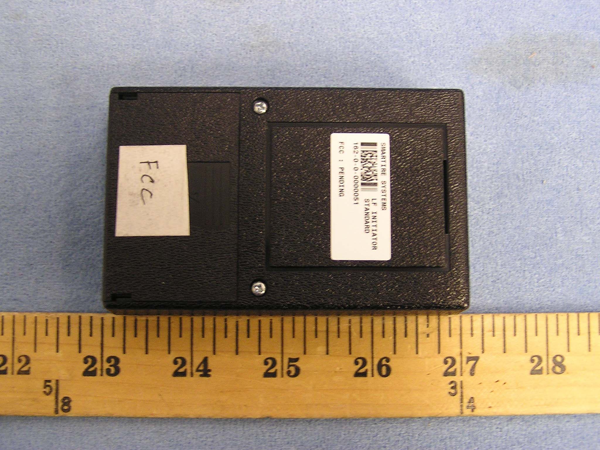
NATLF0162
Jan 06, 2005LF Initiation Tool, 125 kHz LF Transmitter
Equipment Class
DCD - Part 15 Low Power Transmitter Below 1705 kHz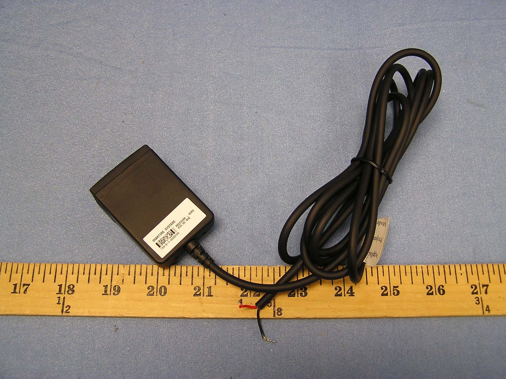
NATMIRD433
Jun 07, 2004433.92MHz Receiver
Equipment Class
CYY - Communications Receiver used w/Pt 15 Transmitter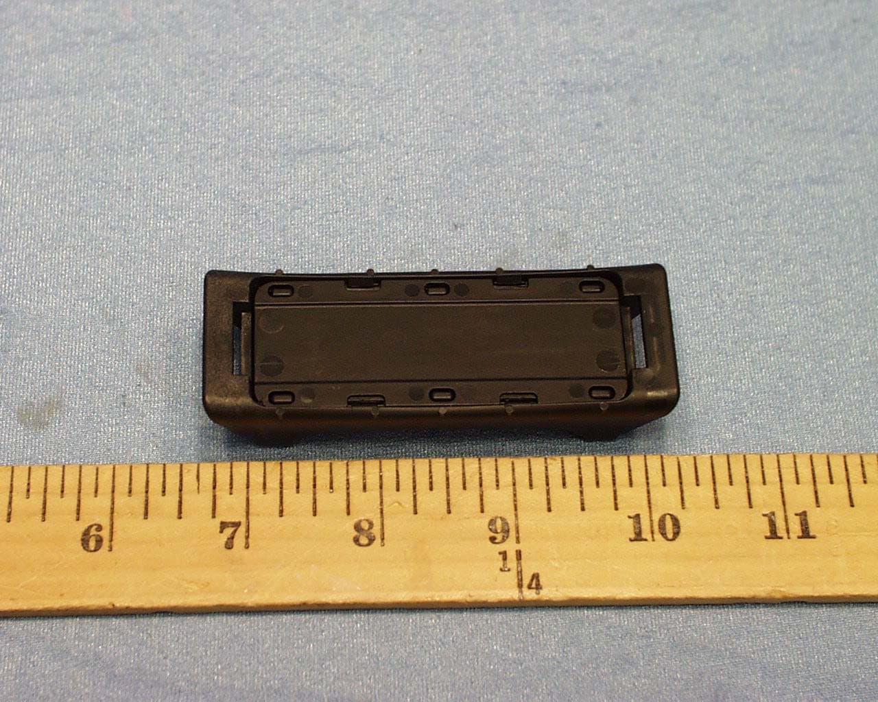
NATTX433CS-3
Jun 03, 2004Tire Monitoring Sensor
Equipment Class
DSC - Part 15 Security/Remote Control Transmitter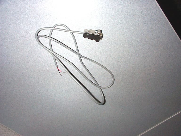
NATRX433-RV-1
Apr 09, 2003Tire Monitoring System-Display Receiver
Equipment Class
CYY - Communications Receiver used w/Pt 15 Transmitter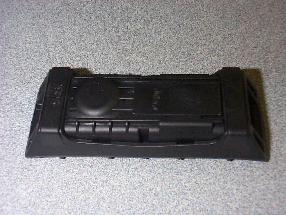
NATTX433CS-2
Apr 08, 2003Tire Monitoring Sensor
Equipment Class
DSR - Part 15 Remote Control/Security Device Transceiver