NATMIRD433433.92MHz Receiver
Bendix Commercial Vehicle Systems LLC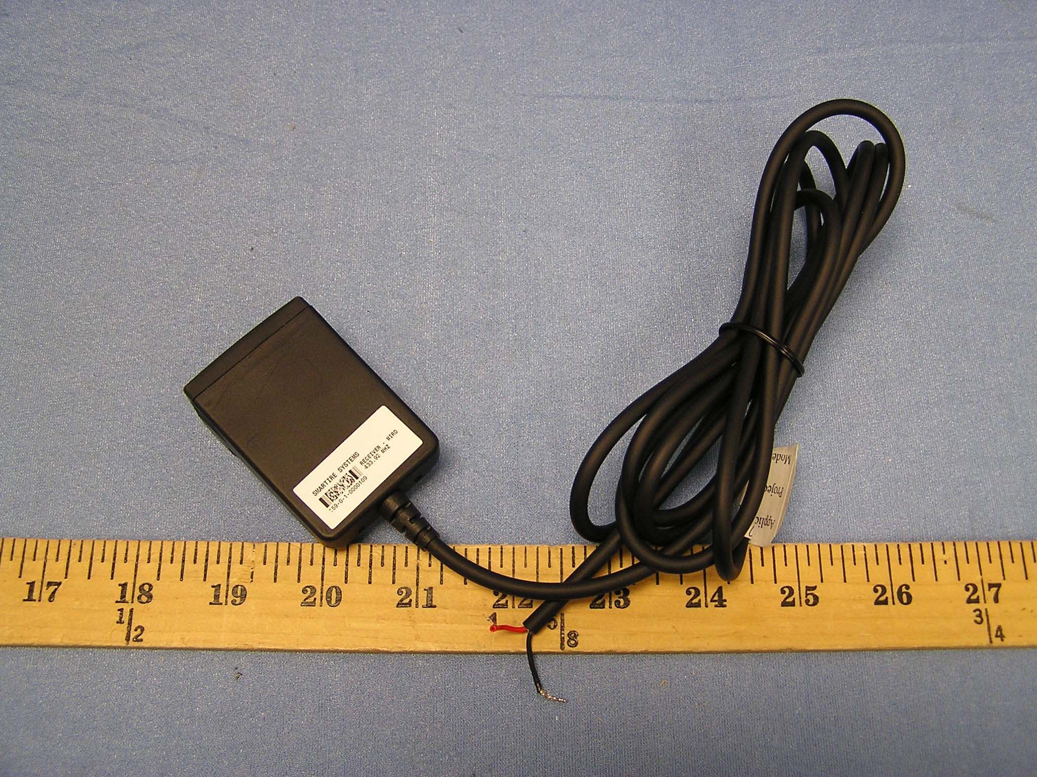
Click to zoom
Application Details
- Equipment Class
- CYY - Communications Receiver used w/Pt 15 Transmitter
- Date of Grant
- Jun 07, 2004
- Application Purpose
- Original Equipment
- Date of Application
- Jun 07, 2004
- Equipment Note
- 433.92MHz Receiver
- Frequency Range
- 433.92000000 - 433.92000000
- Country
- Canada
Documents & Files
Document Text
Text extracted from the exhibit documents filed with the FCC. Open a document above to read the original.
Users Manual
TATTBLELLOFCOCNTNETTNTNSTT System Overview Using the SmarTire Installing the SmarTire Warranty System Scope of Use and Warnings 4 7 13 38 41 USER GUIDE & INSTALLATION MANUAL Thank you for purchasing a SmarTire tire pressure monitoring system for your motorcycle. This manual will provide you with step-by-step instructions to help you successfully install and operate your SmarTire system. Though SmarTire monitors pressure and temp- erature, it is the rider's responsibility to maintain their tires and to react promptly when they receive alerts and warnings. Abnormal tire inflation pressures should be corrected at the earliest opportunity since they can adversely affect the motorcycle's handling characteristics and the tire's structural integrity. PltthtfortheSmarTiretoworkonyour SmarTire Systems reserves the right to change the contents of this manual at any time and without notice. The information contained in this manual is proprietary and may not be reproduced under any circumstances without prior written consent from SmarTire Systems Inc. © 2004 SmarTire Systems In. All rights reserved. 710-0022 • Tires must be tubeless • Maximum Cold Inflation Pressure •must be below 63 psi •Rimsmustbeatleast14"in •diameter and 3" wide SYSTEM OVERVIEW Display / ReceiverSensor / TransmitterStrap SmarTire for Motorcycles consists of the following components: Valve BridgeMounting Kit x 1 x 2 x 2 x 2 x 1 SYSTEM OVERVIEW To successfully install your SmarTire system, you will need: A. Warning Icon B. On Light C. Button D. Front Tire Icon E. Rear Tire Icon F. Temperature Indicator SYSTEM OVERVIEW You are operating your motorcycle in a dangerous condition. Stop and make repairs. You are operating your motorcycle in a dangerous condition. Stop and make repairs. SmarTire actively monitors and displays tire pressure, pressure deviation and tire temperature. The system will warn you if your tire pressures are too low or tire temperatures are too high in order to reduce accident risk, maximize performance, increase tire life and improve fuel efficiency. Getting Started When your motorcycle is started, SmarTire will power up, briefly flash the tire icons and display dashes indicating that it is waiting for tire data. When the motorcycle is ridden over 6 mph (10 kph), SmarTire will begin to receive tire data. When all tire data has been successfully received and the system is operating normally, the front and rear tireiconswillremaindisplayed USING THE SMARTIREUSING THE SMARTIRE - continued. USING THE SMARTIRE - continued.USING THE SMARTIRE - continued. Press the button and SmarTire automatically displays inflation pressure, pressure deviation and temperature for both tires. To quickly toggle through the tire data, press the button repeatedly. Alert Modes The alert icon will activate whenever tire pressure drops below or tire temperature exceeds the factory preset limits. When the tire condition has been corrected, the alert icon will turn off. In all cases, a tire icon will indicate which tire is affected. SmarTire has three alert modes: The Pressure / Temperature Relationship When a motorcycle is ridden, the tires heat up and the actual pressure inside the tire increases. When displaying pressure, SmarTire displays actual pressure values without compensating for pressure changes caused by temperature variations. SmarTire also displays Pressure Deviation, which is the difference between the calculated pressure that should be in the tire at the current tire temperature and the actual measured tire pressure. For example, a Pressure Deviation value of -3 indicates that you should increase that tire's pressure by 3 psi. The Pressure Deviation is accurate regardless of the temperature of the tire. For a more technical description of temperature compensation, please visit our website at www.smartire.com. The Pressure Deviation Alert is set to trigger if the pressure in either your front or rear tire is 15% below or above the temperature compensated cold or recommended inflation pressure (see Pressure / Temperature Relation- ship). The alert icon will flash and the pressure deviation is displayed. • The Low Pressure Alert is set to trigger if the pressure in either tire falls below 25% of the cold inflation pressure. The alert icon will activate and the tire pressure is displayed. Note: The warning icon and pressure deviation will remain illuminated until air is added to the flat tire. • The High Temperature Alert is set to trigger if the temperature in either tire exceeds 176°F (80°C). The alert icon will flash and the tire temperature is displayed. • SmarTire starts to receive tire data only when your motorcycle reaches 6 mph (10 kph). If you want to access tire data while stopped, for example when filling tires at a service station, do not turn off your motorcycle. USING THE SMARTIRE INSTALLING THE SENSORS In this section, you will learn how to mount a sensor on a rim. Please read this section carefully a dfollohlhatyou dono Wrap the strap around the rim and mark 1" past the worm gear for cutting. You may want to temporarily adjust tire pressures to safely carry a passenger or additional loads. This should always be done as per the motorcycle owner's manual. If the motorcycle tire pressure settings are changed, SmarTire must learn the new values. To update the cold inflation pressure: USING THE SMARTIRE - continued. Adjust the pressures in both the front and rear tires to the desired values when the tires are cold. 1. Turn on the motorcycle and immediately press and hold the button until the letters 'CP' are displayed. 2. Ride the motorcycle above 6 mph (10 kph). The new settings will be automatically saved and the unit will exit the 'Pressure Adjust' mode. 3. INSTALLING THE DISPLAY- continued. Wire the display/receiver to the motorcycle connecting the positive wire (red) to the power supply through an ignition keyed circuit and the negative wire (black) to ground. For some motorcycles, it is easiest to connect to an ig…
Text truncated - open the document above for the full version.
Cover Letter(s)
X:\Projects\200-0149-Motorcycle-REC-DISP\FCC\motorcycle receiver\Request for Confidentiality.doc SmarTire Systems Inc. Suite 150, 13151 Vanier Place Richmond, British Columbia Canada, V6V 2J1 T: 604.276.9884 F: 604.276.2350 www.smartire.com SMTR: OTCBB Date: March 29, 2004 Federal Communications Commission Equipment Authorization branch 7435 Oakland Mills Road Columbia, MD 21046 Re: Request for Confidentiality Gentlemen: In reference to the application under FCC ID NATMIRD433,and pursuant to Sections 0.457(d)(l)(ii) and 0.459 of the Commission’s Rules, the Applicant hereby requests confidential treatment of the accompanying information as outlined below: Schematics Block Diagrams Theory of Operation . These documents contain detailed system and equipment description and related information about the product that SmarTire Systems Inc. considers to be proprietary, confidential, and a custom design and, otherwise, would not release to the general public. Since this design is a basis from which future technological products will evolve, SmarTire Systems Inc. considers that this information would be of benefit to its competitors, and that disclosure of the information in these documents would give competitors an unfair advantage in the market. Sincerely, Robert G. Patterson Senior RF Engineer SmarTire Systems Inc.
ID Label/Location Info
PROPOSED FCC ID LABEL AND LOCATION SMARTIRE SYSTEMS INC. This device complies with Part 15 of the FCC Rules. Operation is subject to the following two conditions: (1) this device may not cause harmful interference, and (2) this device must accept any interference received, including interference that may cause undesired operation. FCC ID: NATMIRD433 FCC ID LABEL
Test Report
ELECTROMAGNETIC EMISSIONS COMPLIANCE REPORT CERTIFICATION TO FCC PART 15 REQUIREMENTS for UNINTENTIONAL RADIATOR 433.92 MHz RECEIVER MODEL: 200.0149 FCC ID NO: NATMIRD433 REPORT NO: 04U2633-1 ISSUE DATE: MARCH 30, 2004 Prepared for SMARTIRE SYSTEM INC. #150 13151 VANIER PLACE RICHMOND, BC V6V2J1 CANADA Prepared by COMPLIANCE ENGINEERING SERVICES, INC. 561 F MONTEREY ROAD MORGAN HILL, CA 95037 TEL: 408-463-0885 FAX: 408-463-0888 REPORT NO: 04U12633-1 DATE: March 30, 2004 EUT: 433.92 MHz RECEIVER FCC ID: NATMIRD433 Page 2 of 11 COMPLIANCE CERTIFICATION SERVICES CCS DOCUMENT NO: CCSUP4021B 561 F MONTEREY ROAD, MORGAN HILL, CA 95037 TEL:(408) 463-0885 FAX:(408) 463-0888 This report shall not be reproduced except in full, without written approval from CCS. TABLE OF CONTENTS 1. VERIFICATION OF COMPLIANCE.........................................................................................................................3 2. PRODUCT DESCRIPTION............................................................................................................................................4 3. TEST FACILITY................................................................................................................................................................4 4. FACILITIES AND ACCREDITATION......................................................................................................................4 5. MEASUREMENT EQUIPMENT USED.....................................................................................................................5 6. MEASUREMENT EQUIPMENT USED.....................................................................................................................5 7. TEST CONFIGURATION...............................................................................................................................................6 8. TESTS CONDUCTED......................................................................................................................................................6 9. RADIATED EMISSION TEST PROCEDURE.........................................................................................................7 10. EQUIPMENT MODIFICATIONS...........................................................................................................................7 11. TEST CONFIGURATION PHOTOS (RADIATED EMISSION TEST)......................................................8 REPORT NO: 04U12633-1 DATE: March 30, 2004 EUT: 433.92 MHz RECEIVER FCC ID: NATMIRD433 Page 3 of 11 COMPLIANCE CERTIFICATION SERVICES CCS DOCUMENT NO: CCSUP4021B 561 F MONTEREY ROAD, MORGAN HILL, CA 95037 TEL:(408) 463-0885 FAX:(408) 463-0888 This report shall not be reproduced except in full, without written approval from CCS. 1. VERIFICATION OF COMPLIANCE COMPANY NAME : SMARTIRE SYSTEMS, INC. #150 13151 VANIER PLACE RICHMOND, BC V6V2J1 CANADA CONTACT PERSON : ROBERT PATTERSON EUT DESCRIPTION : 433.92 MHz RECEIVER MODEL NAME/NUMBER : 200.0149 DATE TESTED : 03/30/2004 REPORT NUMBER : 04U2633-1 TYPE OF EQUIPMENT SECURITY EQUIPMENT (UNINTENTIONAL RADIATOR) EQUIPMENT TYPE 433.92 MHz SUPER HETERPDYNE RECEIVER MEASUREMENT PROCEDURE ANSI 63.4 / 2001 LIMIT TYPE CERTIFICATION FCC RULE CFR 47, PART 15.109 The above equipment was tested by Compliance Engineering Services, Inc. for compliance with the requirements set forth in CFR 47, PART 15. This said equipment in the configuration described in this report shows that maximum emission levels emanating from equipment are within the compliance requirements. Tested By: CHIN PANG EMC TECHNICIAN COMPLIANCE CERTIFICATION SERVICES Approved & Released By: THU CHAN EMC SUPERVISOR COMPLIANCE CERTIFICATION SERVICES REPORT NO: 04U12633-1 DATE: March 30, 2004 EUT: 433.92 MHz RECEIVER FCC ID: NATMIRD433 Page 4 of 11 COMPLIANCE CERTIFICATION SERVICES CCS DOCUMENT NO: CCSUP4021B 561 F MONTEREY ROAD, MORGAN HILL, CA 95037 TEL:(408) 463-0885 FAX:(408) 463-0888 This report shall not be reproduced except in full, without written approval from CCS. 2. PRODUCT DESCRIPTION The SmarTire Receiver 200.0149 is a 433.92MHz super heterodyne receiver used in the SmarTire motorcycle Receiver. It receives wireless signals transmitted from the sensor modules mounted inside the tires of the automobile. The signal is demodulated by the receiver and processed by a microprocessor. The status of the tire pressure is then displayed. 3. TEST FACILITY The 3 meter open area test site and conducted measurement facility used to collect the radiated data is located at 561F Monterey Road, Morgan Hill, California, U.S.A. A detailed description of the test facilities was submitted to the Commission on May 27, 1994. The measuring instrument which was utilized in performing the tests documented herein has been calibrated in accordance with the manufacturer's recommendations for utilizing calibration equipment which is traceable to recognized national standards. 4. FACILITIES AND ACCREDITATION The test sites and measurement facilities used to collect data are located at 561F Monterey Road, Morgan Hill, California, USA. The sites are constructed in conformance with the requirements of ANSI C63.4, ANSI C63.7 and CISPR Publication 22. All receiving equipment conforms to CISPR Publication 16-1, “Radio Interference Measuring Apparatus and Measurement Methods.” CCS is accredited by NVLAP, Laboratory Code 200065-0. The full scope of accreditation can be viewed at http://www.ccsemc.com. No part of this report may be used to claim or imply product endorsement by NVLAP or any agency of the US Government. REPORT NO: 04U12633-1 DATE: March 30, 2004 EUT: 433.92 MHz RECEIVER FCC ID: NATMIRD433 Page 5 of 11 COMPLIANCE CERTIFICATION SERVICES CCS DOCUMENT NO: CCSUP4021B 561 F MONTEREY ROAD, MORGAN HILL, CA 95037 TEL:(408) 463-0885 FAX:(408) 463-0888 This report shall not be reproduced except in full, without written approval from CCS. 5. MEASUREMENT EQUIPMENT USED TEST EQUIPMENT LIST Name of Equipment…
Text truncated - open the document above for the full version.
Test Setup Photos
REPORT NO: 04U12633-1 DATE: March 30, 2004 EUT: 433.92 MHz RECEIVER FCC ID: NATMIRD433 Page 8 of 11 COMPLIANCE CERTIFICATION SERVICES CCS DOCUMENT NO: CCSUP4021B 561 F MONTEREY ROAD, MORGAN HILL, CA 95037 TEL:(408) 463-0885 FAX:(408) 463-0888 This report shall not be reproduced except in full, without written approval from CCS. 11. TEST CONFIGURATION PHOTOS (Radiated Emission Test)
Contact Information
Applicant
Robert Patterson(RF Engineer)
Test Firm
Compliance Certification Services IncSteve Cheng
Technical Specifications
| # | Rule Parts | Frequency Range | Power Output |
|---|---|---|---|
| 1 | 15B | 433.92 MHz - 433.92 MHz | - |
Other Applications from Bendix Commercial Vehicle Systems LLC
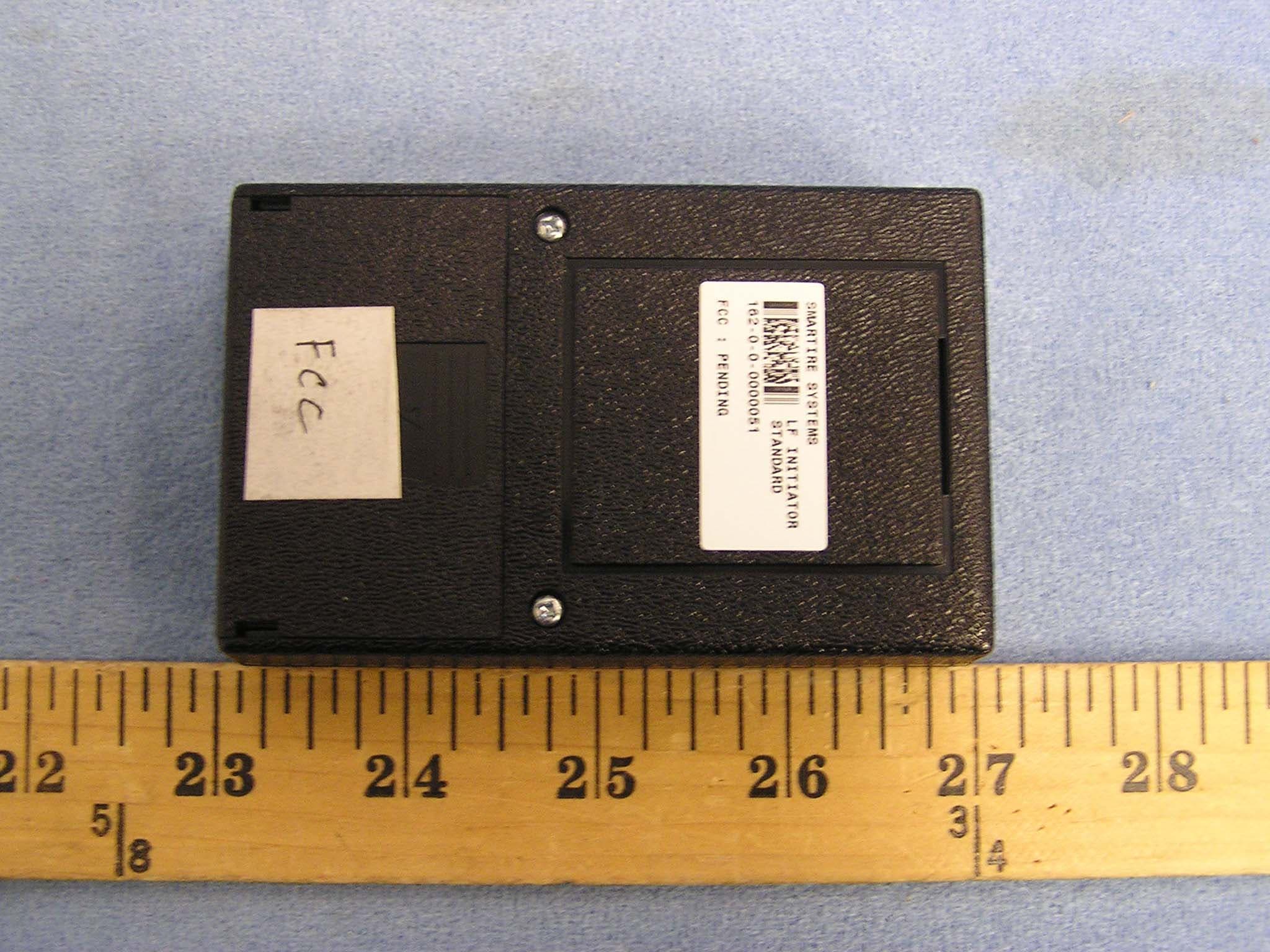
NATLF0162
Jan 06, 2005LF Initiation Tool, 125 kHz LF Transmitter
Equipment Class
DCD - Part 15 Low Power Transmitter Below 1705 kHz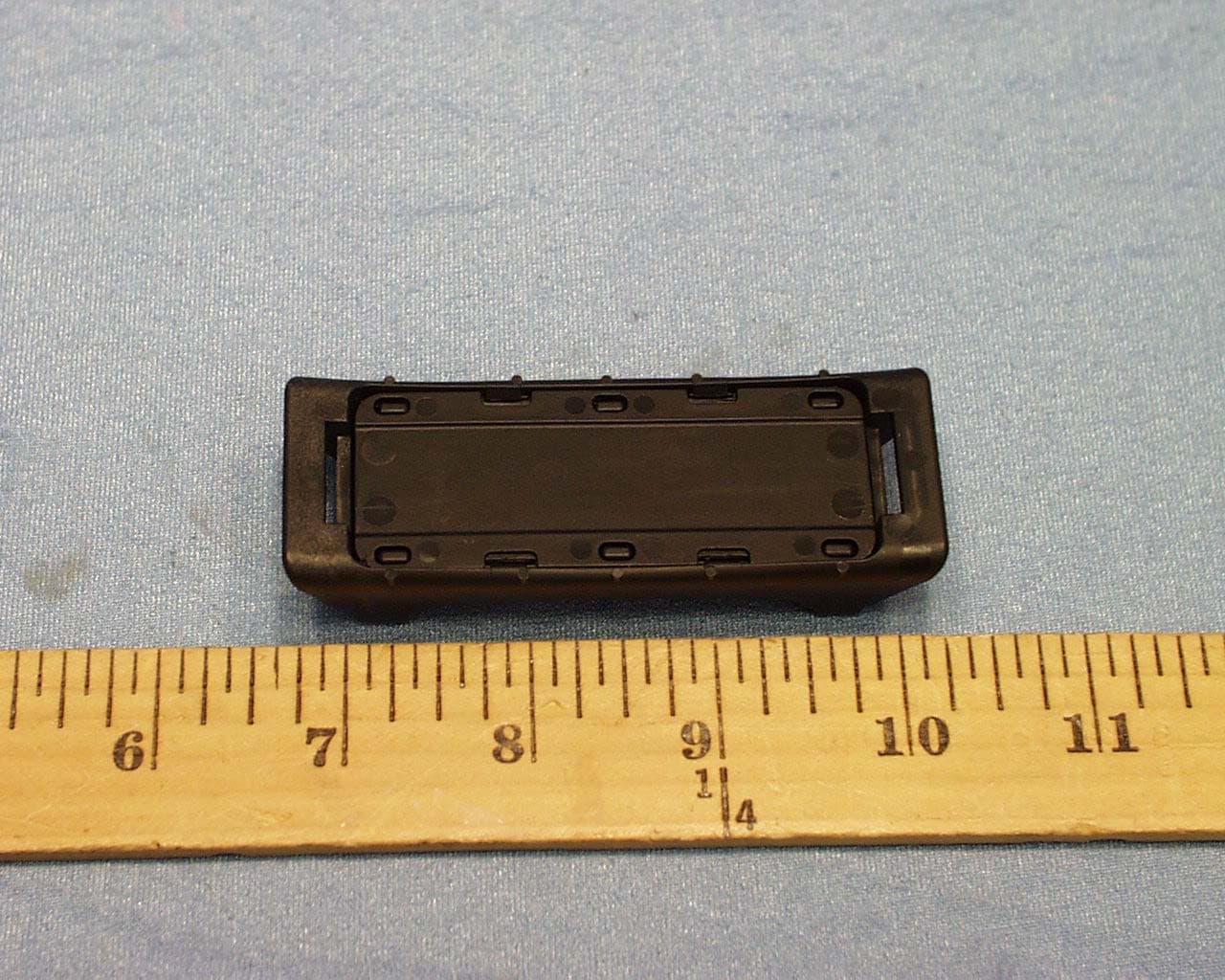
NATTX433CS-3
Jun 03, 2004Tire Monitoring Sensor
Equipment Class
DSC - Part 15 Security/Remote Control Transmitter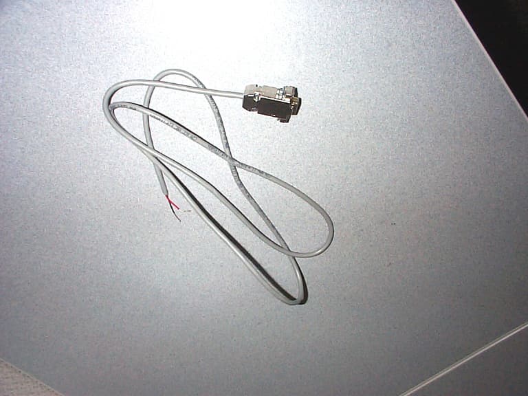
NATRX433-RV-1
Apr 09, 2003Tire Monitoring System-Display Receiver
Equipment Class
CYY - Communications Receiver used w/Pt 15 Transmitter
NATTX433CS-2
Apr 08, 2003Tire Monitoring Sensor
Equipment Class
DSR - Part 15 Remote Control/Security Device Transceiver
NATRX433R-2
Sep 16, 2001Receiver For a Wireless Tire Monitoring System
Equipment Class
CYY - Communications Receiver used w/Pt 15 Transmitter