NATLF0162LF Initiation Tool, 125 kHz LF Transmitter
Bendix Commercial Vehicle Systems LLC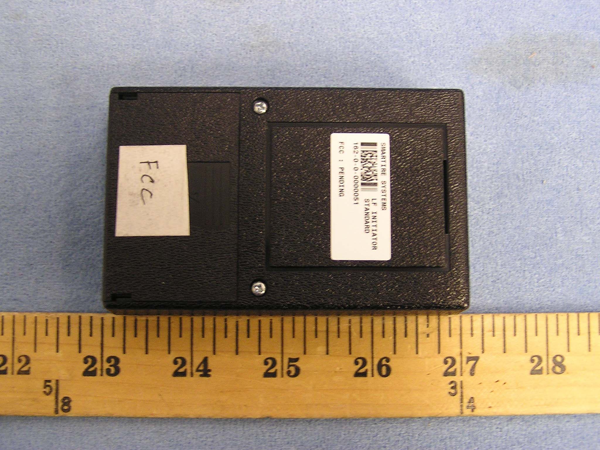
Click to zoom
Application Details
- Equipment Class
- DCD - Part 15 Low Power Transmitter Below 1705 kHz
- Date of Grant
- Jan 06, 2005
- Application Purpose
- Original Equipment
- Date of Application
- Jan 06, 2005
- Equipment Note
- LF Initiation Tool, 125 kHz LF Transmitter
- Frequency Range
- 0.12500000 - 0.12500000
- Country
- Canada
Documents & Files
Document Text
Text extracted from the exhibit documents filed with the FCC. Open a document above to read the original.
Users Manual
LF Initiator Operating Instructions Rev 1.0Document #: 710.0026 1 SmarTire LF Initiator -Operating Instructions The SmarTire LF Initiator is a wireless service tool that facilitates the learning of sensor ID numbers into the receiver during system setup on a vehicle. The Initiator works in conjunction with the Commercial high pressure sensors*. *LF Initiator is not compatible with Low Pressure Sensors (SmarTire for Passenger Car products that measure to a maximum of 65 PSI). Product Configurations SmarTire Part No. DescriptionProduct Application 090.0006Standard Function LF Initiator - Initiate, De-Energize, Learn Dealer tool for RV and Commercial installations Product Functions BUTTONFUNCTION Initiate This function is used after the sensors are installed to confirm that the sensor was programmed properly. Pressing this button next to the sensor causes the sensor to transmit its ID, pressure and temperature readings. De-energize This function should only be used when the sensors are taken out of the tire and need to be shipped back to the supplier. Pressing this button next to the sensor causes the sensor to stop transmitting. Learn This function is used at the time of sensor installation. Pressing this button next to the sensor causes the sensor to transmit its unique ID number for the purpose of programming the Receiver. LED Functions LIGHT COLORFUNCTION Green LF Initiator is working properly. Red LF Initiator is not working properly. Contact SmarTire regarding repair or replacement. Orange Battery is low. LF Initiator Operating Instructions Rev 1.0Document #: 710.0026 2 Activating the LF Initiator The Initiator is powered with a 9 Volt battery that is installed by opening the battery access panel on the back. An ON / OFF switch is located on the right side and this should be pushed upward to turn the Initiator “ON”anddownwardtoturntheInitiator“OFF.” Using the LF Initiator The Initiator has a transmission range of approximately 2 feet. To ensure proper reception, the Initiator should be within this transmission range and the Initiator must be held facing the sensor for at least 5 seconds after the button is pressed. Sensors are normally located adjacent to the valve’s location (figure 1). Hold the Initiator against the tire and point it toward the sensor location from a position slightly outside the rim flange (figures 2 and 3). Figure 1Figure 2Figure 3 NOTE: Normally dual tire assemblies are installed with their valves located 180 degrees from each other. This means that the sensors will also be located 180 degrees from each other and initiating either the outboard or inboard sensors will not cause the other sensor to respond because of the mass of the wheel and hub separating the two locations. The Initiator held against the sidewall of the outboard tire / wheel assembly and pointed toward the location of the sensor on the inboard tire / wheel assembly will be within LF field detection range. LF Initiator Operating Instructions Rev 1.0Document #: 710.0026 3 Programming Newly Installed Sensors 1. Install the sensors on the wheels as described in the SmarTire for RV Installation Guide, and then installall of Tire / Wheel assemblies, onto the vehicle; 2. Power up Receiver and Full Function Display (FFD) by switching ignition on and setting the Receiver into ‘LEARN’ mode as described in the FFD User’s Manual; 3. On the Display, select the desired tire position. The outline of the wheel position to be programmed will flash; 4. Position the Initiator against the tire’s sidewall, press the LEARN button and hold in that location for at least 5 seconds, as described in the previous section. The Receiver registers a signal reception from that sensor by showing a filled in wheel icon on the Display; NOTE: For the inboard locations of dual tires, the initiator can be held against the outboard tire sidewall in line with the position of the inboard sensor to initiate the transmission without having to reach around the outer tire / wheel assembly; 5. If programming more sensors in the system, select the next tire location on the FFD and repeat step #4 until all sensor ID numbers and their appropriate locations on the vehicle have been learned by the Receiver; 6. Exit the Receiver ‘LEARN’ mode by pressing the “Set” button on the Display; NOTE: If an ‘ERR’ message is displayed together with flashing tire locations, those indicated locations have been programmed with the same sensor ID numbers. In this case, press the TIRE button on the FFD to re–enter the Receiver ‘LEARN’ mode and reprogram the flashing sensor locations; 7. Press the “Set” button again to completely exit from the receiver programming modes and save the sensor ID numbers to the Receiver memory; Verifying Correct Installation To check correct ID programming of the receiver, power up the receiver and utilize the INITIATE button on the Initiator as described in step #4 to cause each sensor to transmit. Alternatively, drivethe vehicle above ~ 6 mph. If any locations are not being received, it is likely that the programmed ID number is incorrect and programming the sensors using the ‘LEARN’ function will need to be repeated for those locations. LF Initiator Operating Instructions Rev 1.0Document #: 710.0026 4 FCC NOTICE This device complies with Part 15 of the FCC Rules. Operation is subject to thefollowing two conditions: (1) this device may not cause harmful interference, and(2) this device must accept any interference received, including interference thatmay cause undesired operation.This equipment has been tested and found to comply with the limits for a Class Bdigital device, pursuant to Part 15 of the FCC Rules. These limits are designed toprovide reasonable protection against harmful interference in a residentialinstallation. This equipment generates, uses and can radiate radio frequency energyand, if not installed and used in accordance with the instructions, may cause harmfulinterference to radio communications. However, there is …
Text truncated - open the document above for the full version.
Cover Letter(s)
X:\Projects\200-0161-LF-Initiator-SmarTire\FCC\Request for Confidentiality.doc SmarTire Systems Inc. Suite 150, 13151 Vanier Place Richmond, British Columbia Canada, V6V 2J1 T: 604.276.9884 F: 604.276.2350 www.smartire.com SMTR: OTCBB Date: December 2, 2004 Federal Communications Commission Equipment Authorization branch 7435 Oakland Mills Road Columbia, MD 21046 Re: Request for Confidentiality Gentlemen: In reference to the application under FCC ID NATLF0162 ,and pursuant to Sections 0.457(d)(l)(ii) and 0.459 of the Commission’s Rules, the Applicant hereby requests confidential treatment of the accompanying information as outlined below: Schematics Block Diagrams Theory of Operation . These documents contain detailed system and equipment description and related information about the product that SmarTire Systems Inc. considers to be proprietary, confidential, and a custom design and, otherwise, would not release to the general public. Since this design is a basis from which future technological products will evolve, SmarTire Systems Inc. considers that this information would be of benefit to its competitors, and that disclosure of the information in these documents would give competitors an unfair advantage in the market. Sincerely, Robert G. Patterson Senior RF Engineer SmarTire Systems Inc.
Cover Letter(s)
X:\Projects\200-0161-LF-Initiator-SmarTire\FCC\authorization.doc SmarTire Systems Inc. Suite 150, 13151 Vanier Place Richmond, British Columbia Canada, V6V 2J1 T: 604.276.9884 F: 604.276.2350 www.smartire.com SMTR: OTCBB Date: December 2, 2004 Federal Communications Commission Authorization and Evaluation Division Equipment Authorization Branch 7435 Oakland Mills Road Columbia, MD 21046 To whom it may concern: We, the undersigned, hereby authorize Compliance Engineering Services, Inc. to act on our behalf in all manners relating to application for equipment authorization, including signing of all documents relating to these matters. Any and all acts carried out by Compliance Engineering Service, Inc. on our behalf shall have the same effect as acts of our own. We, the undersigned, hereby certify that we are not subject to a denial of federal benefits, that includes FCC benefits, pursuant to Section 5301 of the Anti-Drug Abuse Act of 1988, 21 U.S.C. 853(a). This authorization is valid until further written notice from the applicant. Sincerely Yours, Robert G. Patterson Senior RF Engineer SmarTire Systems Inc.
ID Label/Location Info
PROPOSED FCC ID LABEL AND LOCATION SMARTIRE SYSTEMS INC. This device complies with Part 15 of the FCC Rules. Operation is subject to the following two conditions: (1) this device may not cause harmful interference, and (2) this device must accept any interference received, including interference that may cause undesired operation. FCC ID: NATLF0162 FCC ID LABEL
Test Report
FCC CFR47 PART 15 SUBPART C CERTIFICATION TEST REPORT FOR LF INITIATION TOOL, 125 kHz LF TRANSMITTER MODEL NUMBER: 200.0162 FCC ID: NATLF0162 REPORT NUMBER: 04U3109-1 ISSUE DATE: DECEMBER 15, 2004 Prepared for SMARTIRE 13151 VANIER PLACE, STE. 150 RICHMOND, BC V6V 2J1, CANADA Prepared by COMPLIANCE CERTIFICATION SERVICES 561F MONTEREY ROAD, MORGAN HILL, CA 95037, USA TEL: (408) 463-0885 FAX: (408) 463-0888 REPORT NO: 04U3109-1 DATE: DECEMBER 15, 2004 EUT: LF INITIATION TOOL, 125 kHz LF TRANSMITTER FCC ID: NATLF0162 Page 2 of 21 COMPLIANCE CERTIFICATION SERVICES DOCUMENT NO: CCSUP4031A 561F MONTEREY ROAD, MORGAN HILL, CA 95037 USA TEL: (408) 463-0885 FAX: (408) 463-0888 This report shall not be reproduced except in full, without the written approval of CCS. Revision History Rev. Revisions Revised By REPORT NO: 04U3109-1 DATE: DECEMBER 15, 2004 EUT: LF INITIATION TOOL, 125 kHz LF TRANSMITTER FCC ID: NATLF0162 Page 3 of 21 COMPLIANCE CERTIFICATION SERVICES DOCUMENT NO: CCSUP4031A 561F MONTEREY ROAD, MORGAN HILL, CA 95037 USA TEL: (408) 463-0885 FAX: (408) 463-0888 This report shall not be reproduced except in full, without the written approval of CCS. TABLE OF CONTENTS 1. ATTESTATION OF TEST RESULTS.....................................................................................4 2. TEST METHODOLOGY.........................................................................................................5 3. FACILITIES AND ACCREDITATION...................................................................................5 4. CALIBRATION AND UNCERTAINTY..................................................................................5 4.1. MEASURING INSTRUMENT CALIBRATION......................................................................5 4.2. MEASUREMENT UNCERTAINTY.......................................................................................5 5. EQUIPMENT UNDER TEST..................................................................................................6 5.1. DESCRIPTION OF EUT.....................................................................................................6 5.2. SOFTWARE AND FIRMWARE............................................................................................6 5.3. WORST-CASE CONFIGURATION AND MODE..................................................................6 5.4. DESCRIPTION OF TEST SETUP........................................................................................7 6. TEST AND MEASUREMENT EQUIPMENT.........................................................................9 7. LIMITS AND RESULTS........................................................................................................10 7.1. RADIATED EMISSIONS........................................................Error! Bookmark not defined. 7.1.1. DUTY CYCLE............................................................Error! Bookmark not defined. 7.1.2. TRANSMITTER RADIATED SPURIOUS EMISSIONS (< 30 MHz)...........................10 7.1.3. DIGITAL RADIATED EMISSIONS (Standby Mode)..................................................13 8. SETUP PHOTOS...................................................................................................................17 REPORT NO: 04U3109-1 DATE: DECEMBER 15, 2004 EUT: LF INITIATION TOOL, 125 kHz LF TRANSMITTER FCC ID: NATLF0162 Page 4 of 21 COMPLIANCE CERTIFICATION SERVICES DOCUMENT NO: CCSUP4031A 561F MONTEREY ROAD, MORGAN HILL, CA 95037 USA TEL: (408) 463-0885 FAX: (408) 463-0888 This report shall not be reproduced except in full, without the written approval of CCS. 1. ATTESTATION OF TEST RESULTS COMPANY NAME: SMARTIRE 13151 VANIER PLACE, STE. 150 RICHMOND, BC V6V 2J1, CANADA EUT DESCRIPTION: LF INITIATION TOOL, 125 kHz LF TRANSMITTER MODEL: 200.0162 SERIAL NUMBER: 162-0-0-00000051 DATE TESTED: DECEMBER 09, 2004 APPLICABLE STANDARDS STANDARD TEST RESULTS FCC PART 15 SUBPART C NO NON-COMPLIANCE NOTED Compliance Certification Services, Inc. tested the above equipment in accordance with the requirements set forth in the above standards. The test results show that the equipment tested is capable of demonstrating compliance with the requirements as documented in this report. Note: The results documented in this report apply only to the tested sample, under the conditions and modes of operation as described herein. This document may not be altered or revised in any way unless done so by Compliance Certification Services and all revisions are duly noted in the revisions section. Any alteration of this document not carried out by Compliance Certification Services will constitute fraud and shall nullify the document. No part of this report may be used to claim product certification, approval, or endorsement by NVLAP, NIST, or any government agency. Approved & Released For CCS By: Tested By: THU CHAN CHIN PANG EMC SUPERVISOR EMC TECHNICIAN COMPLIANCE CERTIFICATION SERVICES COMPLIANCE CERTIFICATION SERVICES REPORT NO: 04U3109-1 DATE: DECEMBER 15, 2004 EUT: LF INITIATION TOOL, 125 kHz LF TRANSMITTER FCC ID: NATLF0162 Page 5 of 21 COMPLIANCE CERTIFICATION SERVICES DOCUMENT NO: CCSUP4031A 561F MONTEREY ROAD, MORGAN HILL, CA 95037 USA TEL: (408) 463-0885 FAX: (408) 463-0888 This report shall not be reproduced except in full, without the written approval of CCS. 2. TEST METHODOLOGY The tests documented in this report were performed in accordance with ANSI C63.4-2003, FCC CFR 47 Part 2 and FCC CFR 47 Part 15. 3. FACILITIES AND ACCREDITATION The test sites and measurement facilities used to collect data are located at 561F Monterey Road, Morgan Hill, California, USA. The sites are constructed in conformance with the requirements of ANSI C63.4, ANSI C63.7 and CISPR Publication 22. All receiving equipment conforms to CISPR Publication 16-1, “Radio Interference Measuring Apparatus and Measurement Methods.” CCS is accredited by NVLAP, Laboratory Code 200065-0. The full scope of accreditation can be viewed at http://www.ccsemc.com. 4. …
Text truncated - open the document above for the full version.
Test Setup Photos
REPORT NO: 04U3109-1 DATE: DECEMBER 15, 2004 EUT: LF INITIATION TOOL, 125 kHz LF TRANSMITTER FCC ID: NATLF0162 Page 20 of 24 COMPLIANCE CERTIFICATION SERVICES DOCUMENT NO: CCSUP4031A 561F MONTEREY ROAD, MORGAN HILL, CA 95037 USA TEL: (408) 463-0885 FAX: (408) 463-0888 This report shall not be reproduced except in full, without the written approval of CCS. 8. SETUP PHOTOS DIGITAL DEVICE RADIATED EMISSIONS SETUP DIGITAL DEVICE FRONT PHOTO REPORT NO: 04U3109-1 DATE: DECEMBER 15, 2004 EUT: LF INITIATION TOOL, 125 kHz LF TRANSMITTER FCC ID: NATLF0162 Page 21 of 24 COMPLIANCE CERTIFICATION SERVICES DOCUMENT NO: CCSUP4031A 561F MONTEREY ROAD, MORGAN HILL, CA 95037 USA TEL: (408) 463-0885 FAX: (408) 463-0888 This report shall not be reproduced except in full, without the written approval of CCS. DIGITAL DEVICE BACK PHOTO REPORT NO: 04U3109-1 DATE: DECEMBER 15, 2004 EUT: LF INITIATION TOOL, 125 kHz LF TRANSMITTER FCC ID: NATLF0162 Page 22 of 24 COMPLIANCE CERTIFICATION SERVICES DOCUMENT NO: CCSUP4031A 561F MONTEREY ROAD, MORGAN HILL, CA 95037 USA TEL: (408) 463-0885 FAX: (408) 463-0888 This report shall not be reproduced except in full, without the written approval of CCS. RADIATED RF MEASUREMENT SETUP FOR PORTABLE CONFIGURATION X-AXIS FRONT PHOTO REPORT NO: 04U3109-1 DATE: DECEMBER 15, 2004 EUT: LF INITIATION TOOL, 125 kHz LF TRANSMITTER FCC ID: NATLF0162 Page 23 of 24 COMPLIANCE CERTIFICATION SERVICES DOCUMENT NO: CCSUP4031A 561F MONTEREY ROAD, MORGAN HILL, CA 95037 USA TEL: (408) 463-0885 FAX: (408) 463-0888 This report shall not be reproduced except in full, without the written approval of CCS. Y-AXIS FRONT PHOTO REPORT NO: 04U3109-1 DATE: DECEMBER 15, 2004 EUT: LF INITIATION TOOL, 125 kHz LF TRANSMITTER FCC ID: NATLF0162 Page 24 of 24 COMPLIANCE CERTIFICATION SERVICES DOCUMENT NO: CCSUP4031A 561F MONTEREY ROAD, MORGAN HILL, CA 95037 USA TEL: (408) 463-0885 FAX: (408) 463-0888 This report shall not be reproduced except in full, without the written approval of CCS. END OF REPORT Z-AXIS FRONT PHOTO
Contact Information
Applicant
Robert Patterson(RF Engineer)
Test Firm
Compliance Certification Services IncSteve Cheng
Technical Specifications
| # | Rule Parts | Frequency Range | Power Output |
|---|---|---|---|
| 1 | 15C | 0.125 MHz - 0.125 MHz | - |
Other Applications from Bendix Commercial Vehicle Systems LLC
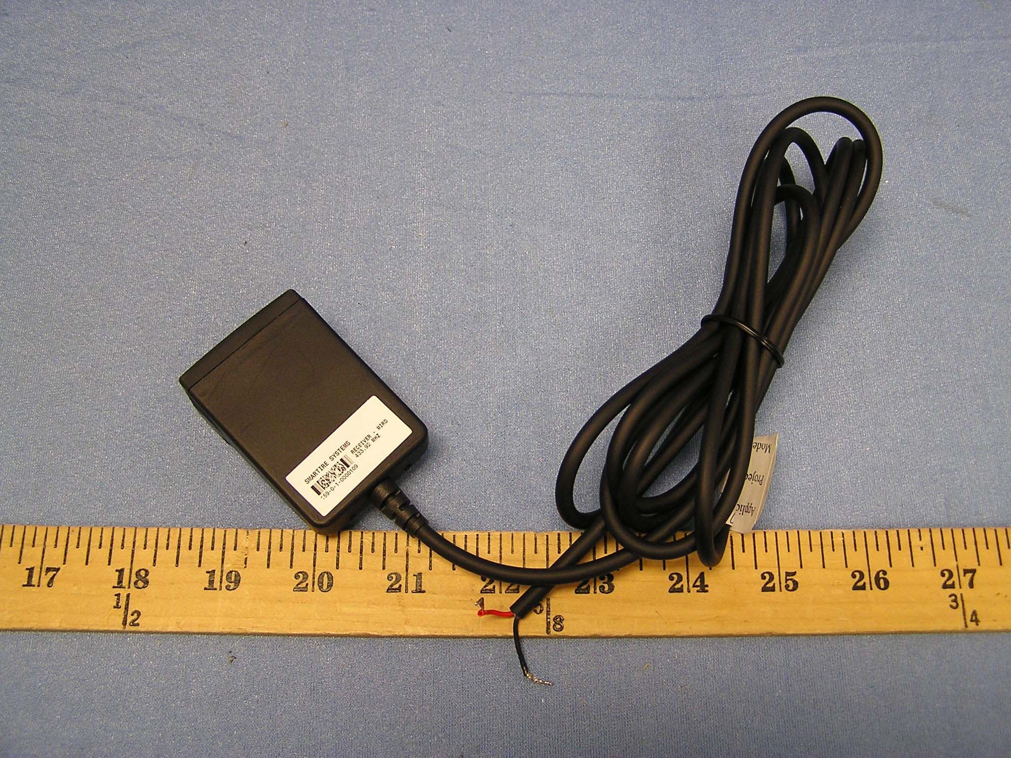
NATMIRD433
Jun 07, 2004433.92MHz Receiver
Equipment Class
CYY - Communications Receiver used w/Pt 15 Transmitter
NATTX433CS-3
Jun 03, 2004Tire Monitoring Sensor
Equipment Class
DSC - Part 15 Security/Remote Control Transmitter
NATRX433-RV-1
Apr 09, 2003Tire Monitoring System-Display Receiver
Equipment Class
CYY - Communications Receiver used w/Pt 15 Transmitter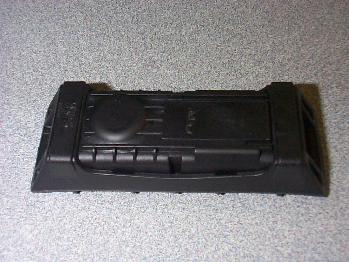
NATTX433CS-2
Apr 08, 2003Tire Monitoring Sensor
Equipment Class
DSR - Part 15 Remote Control/Security Device Transceiver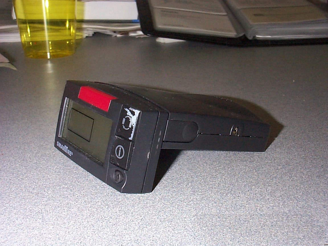
NATRX433R-2
Sep 16, 2001Receiver For a Wireless Tire Monitoring System
Equipment Class
CYY - Communications Receiver used w/Pt 15 Transmitter