NATTX433CS-2Tire Monitoring Sensor
Bendix Commercial Vehicle Systems LLC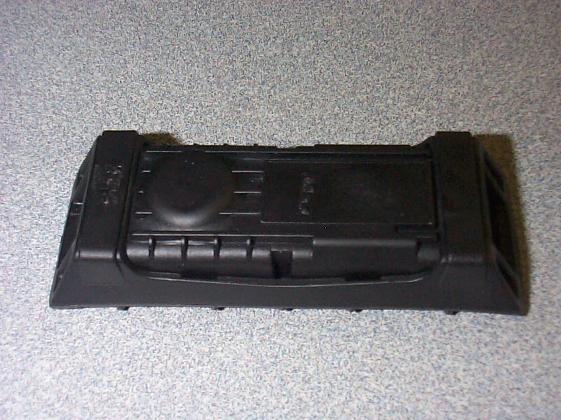
Click to zoom
Application Details
- Equipment Class
- DSR - Part 15 Remote Control/Security Device Transceiver
- Date of Grant
- Apr 08, 2003
- Application Purpose
- Original Equipment
- Date of Application
- Apr 08, 2003
- Equipment Note
- Tire Monitoring Sensor
- Frequency Range
- 433.92000000 - 433.92000000
- Country
- Canada
Documents & Files
Document Text
Text extracted from the exhibit documents filed with the FCC. Open a document above to read the original.
Users Manual
SmarTire Systems Inc. Tire Monitor System Owner’s Manual Draft 2/25/2003 Page 1 This manual is under review by SmarTire Tire Monitor System Owner Manual PN 710.xxxx RV Tow-behind Draft Editors Notes 1. Application; North America, English 2. Prior to issue this manual to be examined and approved by; a. Engineering b. Marketing c. Customer Service 3. Footnotes in this manual refer to the file names for the graphics. Original high resolution graphics are in photoshop format and this manual uses jpg versions of the same graphics. SmarTire Systems Inc. Tire Monitor System Owner’s Manual Draft 2/25/2003 Page 2 This manual is under review by SmarTire Table of Contents Notices..............................................................................................................................................3 FCC Notice.................................................................................................................................................................................3 System Scope of Use and Warnings.....................................................................................................................................3 The SmarTire™ System and Tire Maintenance..............................................................................................................3 System Installation and Usage............................................................................................................................................3 Reacting to Alerts..................................................................................................................................................................3 Getting Started..................................................................................................................................4 Operation..........................................................................................................................................5 How It Works.........................................................................................................................................................................5 Installation........................................................................................................................................6 Transmitter Installation........................................................................................................................................................6 Tools Required.................................................................................................................................................................6 Installing Transmitter on a Wheel.................................................................................................................................7 Mounting Tire with Transmitter on Wheel.................................................................................................................8 De-mounting the Tire with Transmitter Installed.......................................................................................................9 Receiver PN 200.0087........................................................................................................................................................10 Full Function Display PN 200.0068................................................................................................................................11 Service and Warranty......................................................................................................................12 Component Part numbers...................................................................................................................................................12 Troubleshooting...................................................................................................................................................................13 System Default Settings.....................................................................................................................................................13 Technical Specifications....................................................................................................................................................13 Strap Mount Transmitter..............................................................................................................................................13 Receiver...........................................................................................................................................................................13 SmarTire Service Policy – Handling Returned Materials............................................................................................13 US Warranty........................................................................................................................................................................14 Appendix........................................................................................................................................15 Glossary................................................................................................................................................................................15 SmarTire Systems Inc. Tire Monitor System Owner’s Manual Draft 2/25/2003 Page 3 This manual is under review by SmarTire Notices FCC Notice This device complies with Part 15 of the FCC Rules. Operation is subject to the following two conditions: (1) this device may not cause harmful interference, and (2) this device must accept any interference received, including interference that may cause undesired operation. This equipment has been tested and found to comply with the limits for a Class B digital device, pursuant to Part 15 of the FCC Rules. These limits are designed to provide reasonable protection against harmful interference in a residential installatio…
Text truncated - open the document above for the full version.
Users Manual
SmarTire Systems Inc. Tire Monitor System Owner’s Manual Draft 2/25/2003 Page 9 This manual is under review by SmarTire De-mounting the Tire with Transmitter Installed Remove the tire/wheel assembly from vehicle and deflate completely. Loosen both beads with the bead loosener shoe opposite the valve stem (away from the transmitter which is located near the valve stem). Verify the transmitter location. Orient the wheel to place the transmitter 3 in. to the left of the bead guiding shoe so that the mounting bar will clear the transmitter. When lifting the top bead the tire must be clear of the transmitter. Remove the top bead. Set the wheel once more with the transmitter 3 in. to the left of the bead guiding shoe and remove the bottom bead. This will expose the transmitter, which should be checked for correct positioning and a properly snug fit. Transmitter Valve SmarTire Systems Inc. Tire Monitor System Owner’s Manual Draft 2/25/2003 Page 10 This manual is under review by SmarTire Receiver PN 200.0087
Users Manual
SmarTire Systems Inc. Tire Monitor System Owner’s Manual Draft 2/25/2003 Page 11 This manual is under review by SmarTire Full Function Display PN 200.0068 SmarTire Systems Inc. Tire Monitor System Owner’s Manual Draft 2/25/2003 Page 12 This manual is under review by SmarTire Service and Warranty Component Part numbers Bill of Material 101.1404 TMS TOW-BEHIND GENII -------------------------------------------------------------------------------- 1 200.0068 DISPLAY FFD D-2 - REMOTE 1 200.0087 RECEIVER GENII - SHIELDED 4 200.0100 TRANSMITTER - STRAP TS-2 1 260.0150 CONNECTOR PLUG-JACK-JACK AMPHENOL:21900 1 260.0157 CABLE RECEIVER-FFD FOR RV 1 260.0158 POWER CABLE FOR RV RECEIVER 4 264.0115 STRAP - STAINLESS STEEL CLAMP BREEZE:600 356 H 476 B SmarTire Systems Inc. Tire Monitor System Owner’s Manual Draft 2/25/2003 Page 13 This manual is under review by SmarTire Troubleshooting Problem Cause and actions System Default Settings Low Pressure Alert 22 PSI Change in factory only Low Pressure Warning 15 PSI Change in factory only Wheel color codes Right front Green Left front Red Right rear Blue Left rear Yellow Technical Specifications Strap Mount Transmitter Battery Life (Projected) 8.5 Years (normal vehicle use) Operating temperature range -40° F to 257° F (-40° C to 125° C) Storage temperature Range -40° F to 257° F (-40° C to 125° C) Operating humidity 100% Data transmitted Pressure, temperature, battery voltage Data transmission rate Upon startup, then every 3 to 5 minutes (more frequently during a pressure loss incident) Every 15 minutes if pressure is 18 PSI or lower when vehicle is parked. Weight To be determined Size 3-1/4” x 1-1/8” x 1” Frequency 433.92 Mhz Pressure Range 50 to 637.5 kPa (absolute) (7 – 93 PSI) Pressure accuracy +/- 2 PSI Temperature accuracy +/- 3 ºC Start-stop mode Vehicle motion greater than 10kph Method of mounting Strap around the drop center well of the wheel Receiver Power Consumption 125 ma. maximum during alert Operating Temperature Range -40° F to 185° F (-40° C to 85°C) Storage Temperature Range -40° F to 185° F (-40° C to 85° C) Frequency 433.92 MHZ ± 75 kHz Size 2.85” H x 3.08” D x .87” W Weight 67 gm Operating Humidity 100 % non condensing SmarTire Service Policy – Handling Returned Materials To return any materials, call SmarTire Service for a Returned Material Authorization number (RMA). Follow instructions given by the service department for packaging and shipping the product in your area. SmarTire Systems Inc. Tire Monitor System Owner’s Manual Draft 2/25/2003 Page 14 This manual is under review by SmarTire US Warranty This Warranty covers substantial manufacturer’s defects in workmanship and materials. It does not cover any unit that is damaged beyond normal usage, was not properly installed, was subjected to chemical contact, or other acts or omissions not sanctioned by the Owner’s Manual. All components are covered for one (1) years and 50,000 miles following the date of installation. The SmarTire warranty will be honoured by any authorized SmarTire dealer. The owner is required to provide dated proof of purchase. The authorized dealer will determine if there is a warrantable condition associated with materials and/or manufacturing workmanship. If a warrantable condition exists, the component will be replaced free of charge, shipping prepaid. The owner is responsible for any labor and installation charges. A completed Warranty Claim Form must be sent, postage prepaid, with the defective unit to SmarTire USA Inc., 3873C Airport Way, Bellingham, WA 98227-9754. Phone 330-497-0236 The Warranty does not include any further obligation whatsoever, including but not limited to actual installation of the replacement unit on the customer’s vehicle. All other Warranties, express or implied, are disclaimed. All collateral agreements, which purport to modify this Limited Warranty are of no effect. The absolute limit of liability is the purchase price of the unit. SmarTire Systems Inc. is not liable for any direct, consequential, indirect or punitive damages of any kind. SOME STATES DO NOT ALLOW LIMITATIONS ON THE VALIDITY OR LENGTH OF IMPLIED WARRANTIES, SO THE ABOVE LIMITATIONS MAY NOT APPLY TO YOU. SOME STATES DO NOT ALLOW THE EXCLUSION OR LIMITATION OF INCIDENTAL OR CONSEQUENTIAL DAMAGES, SO THE ABOVE LIMITATION OR EXCLUSION MAY NOT APPLY TO YOU. THIS WARRANTY GIVES YOU SPECIFIC LEGAL RIGHTS, AND YOU MAY HAVE OTHER RIGHTS WHICH VARY FROM STATE TO STATE. SmarTire Systems Inc. Tire Monitor System Owner’s Manual Draft 2/25/2003 Page 15 This manual is under review by SmarTire Appendix Glossary Actual Pressure The value of tire air pressure measured by the Transmitter and transmitted to the Receiver. This value is compared to the Required Pressure to active an alert or warning if needed. Cold Pressure The recommended inflation pressure of a tire at ambient temperature (64º F). Low Pressure Alert The audible and visual alert activated when the tire’s Actual Pressure drops to the programmed value. Low Pressure Warning The audible and visual alert activated when the tire’s Actual Pressure drops to the programmed value. This value is lower than the Low Pressure Alert. Receiver The electronic module that receives data from the transmitter and displays tire pressure alerts. Transmitter The wheel mounted electronic module that measures contained air pressure and temperature and transmits this data to the receiver.
Cover Letter(s)
From: Claire Hoque Sent: Tuesday, April 01, 2003 9:45 AM To: Mike Kuo Subject: RE: SMARTIRE SYSTEMS INC. , FCC ID:NATTX433CS-2, AN03T2688 Hi Mike, Here is the answer for Item(3) from Smartire. Question:Item (3) of reply mentioned the silent period (7 seconds) which is less than 10 seconds or 30 times of duration of transmission. Based upon this description, this device does not meet 15.231(e) requirements. Please address this issue. ANSWER: Mode 1: Standard operation while driving: The device transmits one transmission every 5 minutes. Each transmission is 500 ms long. Mode 2: If there is a pressure loss of more than 3 PSI. If the device measures a pressure loss of more than 3 PSI it will transmit one transmission within 7 seconds of the pressure loss. If there was a previous transmission within the last 15 seconds, it will wait 15 seconds before transmitting one transmission. The maximum our device will transmit is one transmission every 15 seconds. Since the transmission is 500 ms long we are allowed to transmit every 500 ms * 30 = 15 seconds. The silent period between transmission will never be less than 15 seconds. Hope this explains more clearly. Thanks, Claire Hoque Compliance Certification Services 561F Montery Road Morgan Hill, CA 95037 Tel: (408) 463-0885 x 123 Fax: (408) 463-0888 -----Original Message----- From: Mike Kuo Sent: Monday, March 31, 2003 5:19 PM To: Claire Hoque Cc: Anne Liang; Thu Chan Subject: RE: SMARTIRE SYSTEMS INC. , FCC ID:NATTX433CS-2, AN03T2688 Hi Claire : Item (3) of reply mentioned the silent period (7 seconds) which is less than 10 seconds or 30 times of duration of transmission. Based upon this description, this device does not meet 15.231(e) requirements. Please address this issue. Best Regards Mike Kuo -----Original Message----- From: Claire Hoque Sent: Monday, March 31, 2003 4:11 PM To: Mike Kuo Cc: Anne Liang; Thu Chan Subject: Re: SMARTIRE SYSTEMS INC. , FCC ID:NATTX433CS-2, AN03T2688 Hi Mike, Here are the answers for SMARTIRE SYSTEMS INC.(03U1767) Question #1: Section 15.231(e) of FCC rules is used for technical assessment. As indicated in section 15.231(e) of FCC rules, the device applied to this section must 1) duration of each transmission shall not be greater than one second, and 2) the silent period between each transmission shall be at least 30 times the duration of the transmission but in no case less than 10 second. The following questions are related to above requirements: a) page 5 of user manual with the following description:" The system operates continuously, transmitting air pressure and temperature data, At approximately 5 minute intervals when the vehicle is moving faster than 6 mph, unless pressure changes, then data is transmitted within 7 seconds." Since the duration of transmitter for total of 10 packets is .5second, 30x0.5second=15second. 7 second silent period is less than the 30 times of duration of transmission and also less than 10 seconds. Please address this non-compliance issue. ANSWER from client: The transmitter transmits as follows: (1) Transmission occurs once every 4 to 6 mintues in rolling mode (2) One transmission consists of 10 packets (2 packets every 100 ms) for 0.5 seconds. (3) During a pressure drop the transmitter transmits one packet within 7 seconds unless a previous transmission occured . If a previous transmission occured it will transmit in 15 seconds. The 3 more packets , one packet every 15 seconds. The device does meet the requirements of FCC. However, I think the manual may be a little misleading as to the wording. Would the manual still need to be updated to reflect the above? Or can we just get by with the explanation I gave. Let me know as it will take a little time to update the manual Question #2: What is the instrument setting used for fundamental field strength measurement? ANSWER; RBW=100KHz VBW=100KHz Question #3: Page 17 of test report can not be read. ANSWER: Pls see the revised test report as attached. Thanks, Claire Hoque Compliance Certification Services 561F Montery Road Morgan Hill, CA 95037 Tel: (408) 463-0885 x 123 Fax: (408) 463-0888
ID Label/Location Info
PROPOSED FCC ID LABEL AND LOCATION SmarTire Systems Inc. This device complies with Part 15 of the FCC Rules. Operation is subject to the following two conditions: (1) this device may not cause harmful interference, and (2) this device must accept any interference received, including interference that may cause undesired operation. FCC ID: NATTX433CS-2 FCC ID LABEL
Test Report
FCC PART 15 SUBPART C CERTIFICATION REPORT FOR 433.92 MHz TIRE MONITORING SYSTEM SENSOR MODEL: 200.0101 FCC ID NO: NATTX433CS-2 REPORT NO: 03U1767-1 ISSUE DATE: FEBUARY 19, 2003 Prepared for SMARTIRE SYSTEMS INC. #150 13151 VANIER PLACE RICHMOND BC CANADA Prepared by COMPLIANCE ENGINEERING SERVICES, INC. d.b.a. COMPLIANCE CERTIFICATION SERVICES 561F MONTEREY ROAD MORGAN HILL, CA 95037 USA TEL: (408) 463-0885 FAX: (408) 463-0888 REPORT NO: 03U1767-1 DATE: FEBUARY 19, 2003 EUT: 433.92 MHz TIRE MONITORING SYSTEM SENSOR FCC ID: NATTX433CS-2 COMPLIANCE CERTIFICATION SERVICES CCS DOCUMENT NO:CCSUP4020B 561F MONTEREY RD., MORGAN HILL, CA 95037, USA TEL:(408)463-0885 FAX:(408)463-0888 This report shall not be reproduced except in full, without the written approval of CCS. This document may be altered or revised by Compliance Certification Services personnel only, and shall be noted in the revision section of the document. TABLE OF CONTENTS PAGE 1. VERIFICATION OF COMPLIANCE........................................................................................3 2. PRODUCT DESCRIPTION........................................................................................................3 3. TEST FACILITY.........................................................................................................................4 4. MEASUREMENT STANDARDS..............................................................................................4 5. TEST METHODOLOGY............................................................................................................4 6. MEASUREMENT EQUIPMENT USED....................................................................................4 7. POWERLINE RFI LIMIT...........................................................................................................5 8. RADIATED EMISSION LIMITS...............................................................................................5 9. SYSTEM TEST CONFIGURATION.........................................................................................6 10. TEST PROCEDURE.................................................................................................................7 11. EQUIPMENT MODIFICATIONS............................................................................................8 12. TEST RESULT..........................................................................................................................9 12.1 MAXIMUM MODULATION PERCENTAGE (M%)...........................................................9 12.2 THE EMISSIONS BANDWIDTH..........................................................................................9 TEST DATA • Maximum Modulation Percentage Plot • Emission Bandwidth Plot • Radiated Emission Worksheet for Peak Measurement • Radiated Emission Worksheet for Average Measurement • EUT Photographs REPORT NO: 03U1767-1 DATE: FEBUARY 19, 2003 EUT: 433.92 MHz TIRE MONITORING SYSTEM SENSOR FCC ID: NATTX433CS-2 Page 3 of 21 COMPLIANCE CERTIFICATION SERVICES CCS DOCUMENT NO:CCSUP4020B 561F MONTEREY RD., MORGAN HILL, CA 95037, USA TEL:(408)463-0885 FAX:(408)463-0888 This report shall not be reproduced except in full, without the written approval of CCS. This document may be altered or revised by Compliance Certification Services personnel only, and shall be noted in the revision section of the document. 1. VERIFICATION OF COMPLIANCE COMPANY NAME : SMARTIRE SYSTEMS INC. #150 13151 VANIER PLACE RICHMOND BC, CANADA EUT DESCRIPTION : 433.92 MHz TIRE MONITORING SYSTEM SENSOR MODEL NO : 200.0101 FCC ID : NATTX433CS-2 DATE TESTED : 2-19-2003 REPORT NUMBER : 03U1767-1 TYPE OF EQUIPMENT TIRE MONITORING SYSTEM SENSOR EQUIPMENT TYPE 433.92MHz, TIRE MONITORING SYSTEM SENSOR MEASUREMENT PROCEDURE ANSI C63.4 / 2001 LIMIT TYPE CERTIFICATION FCC RULE CFR 47, PART 15 The above equipment was tested by Compliance Certification Services for compliance with the requirements set forth in the FCC CFR 47, PART 15. The results of testing in this report apply to the product/system which was tested only. Other similar equipment will not necessarily produce the same results due to production tolerance and measurement uncertainties. Warning : This document reports conditions under which testing was conducted and results of tests performed. This document may not be altered or revised in any way unless done so by Compliance Certification Services and all revisions are duly noted in the revisions section. Any alteration of this document not carried out by Compliance Certification will constitute fraud and shall nullify the document. Tested By: CHIN PANG EMC TECHNICIAN COMPLIANCE CERTIFICATION SERVICES Approved & Released By: THU CHAN EMC SUPERVISOR COMPLIANCE CERTIFICATION SERVICES REPORT NO: 03U1767-1 DATE: FEBUARY 19, 2003 EUT: 433.92 MHz TIRE MONITORING SYSTEM SENSOR FCC ID: NATTX433CS-2 Page 4 of 21 COMPLIANCE CERTIFICATION SERVICES CCS DOCUMENT NO:CCSUP4020B 561F MONTEREY RD., MORGAN HILL, CA 95037, USA TEL:(408)463-0885 FAX:(408)463-0888 This report shall not be reproduced except in full, without the written approval of CCS. This document may be altered or revised by Compliance Certification Services personnel only, and shall be noted in the revision section of the document. 2. PRODUCT DESCRIPTION Fundamental Frequency 433.92 MHz Power Source 3V Battery Transmitting 10 Packet every 4 to 6 minutes Associated Receiver NA Manufacturer SMARTIRE SYSTEMS INC. 3. TEST FACILITY The 3/10/30 meter open area test site and conducted measurement facility used to collect the radiated data is located at 561F Monterey Road, Morgan Hill, California, U.S.A. A detailed description of the test facility was submitted to the Commission on May 27,1994. 4. MEASUREMENT STANDARD The site is constructed and calibrated in conformance with the requirements of ANSI C63.4/2001. 5. TEST METHODOLOGY For an intentional radiator, the spectrum shall be investigated from the lowest radio frequency signal generated in the …
Text truncated - open the document above for the full version.
Test Setup Photos
REPORT NO: 03U1767-1 DATE: FEBUARY 19, 2003 EUT: 433.92 MHz TIRE MONITORING SYSTEM SENSOR FCC ID: NATTX433CS-2 Page 6 of 21 COMPLIANCE CERTIFICATION SERVICES CCS DOCUMENT NO:CCSUP4020B 561F MONTEREY RD., MORGAN HILL, CA 95037, USA TEL:(408)463-0885 FAX:(408)463-0888 This report shall not be reproduced except in full, without the written approval of CCS. This document may be altered or revised by Compliance Certification Services personnel only, and shall be noted in the revision section of the document. 9. SYSTEM TEST CONFIGURATION Use a block of foam and combined it with EUT wrapping rubber band around it. This way it can test X.Y, and Z axis. To activate continuous transmission, place a small plastic block between rubber band and EUT push button. Radiated Open Site Test Set-up X-Axis Y-Axis Z-Axis
Contact Information
Applicant
Robert Patterson(RF Engineer)
Test Firm
Compliance Certification Services IncSteve Cheng
Technical Specifications
| # | Rule Parts | Frequency Range | Power Output |
|---|---|---|---|
| 1 | 15.231(e) | 433.92 MHz - 433.92 MHz | - |
Other Applications from Bendix Commercial Vehicle Systems LLC
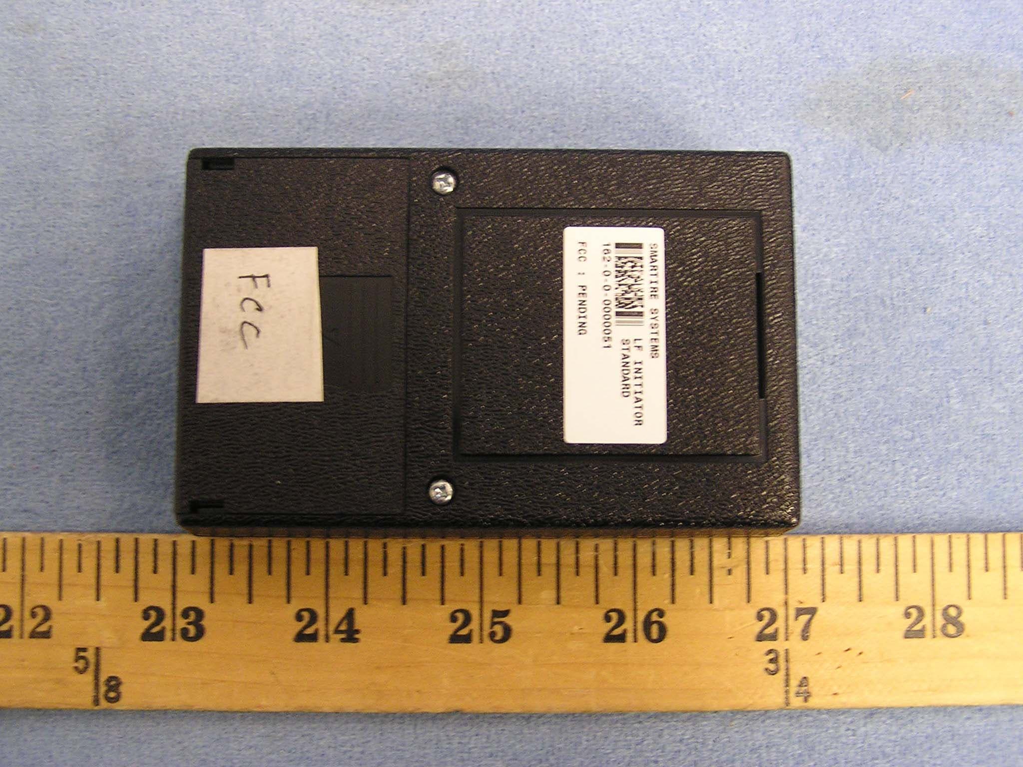
NATLF0162
Jan 06, 2005LF Initiation Tool, 125 kHz LF Transmitter
Equipment Class
DCD - Part 15 Low Power Transmitter Below 1705 kHz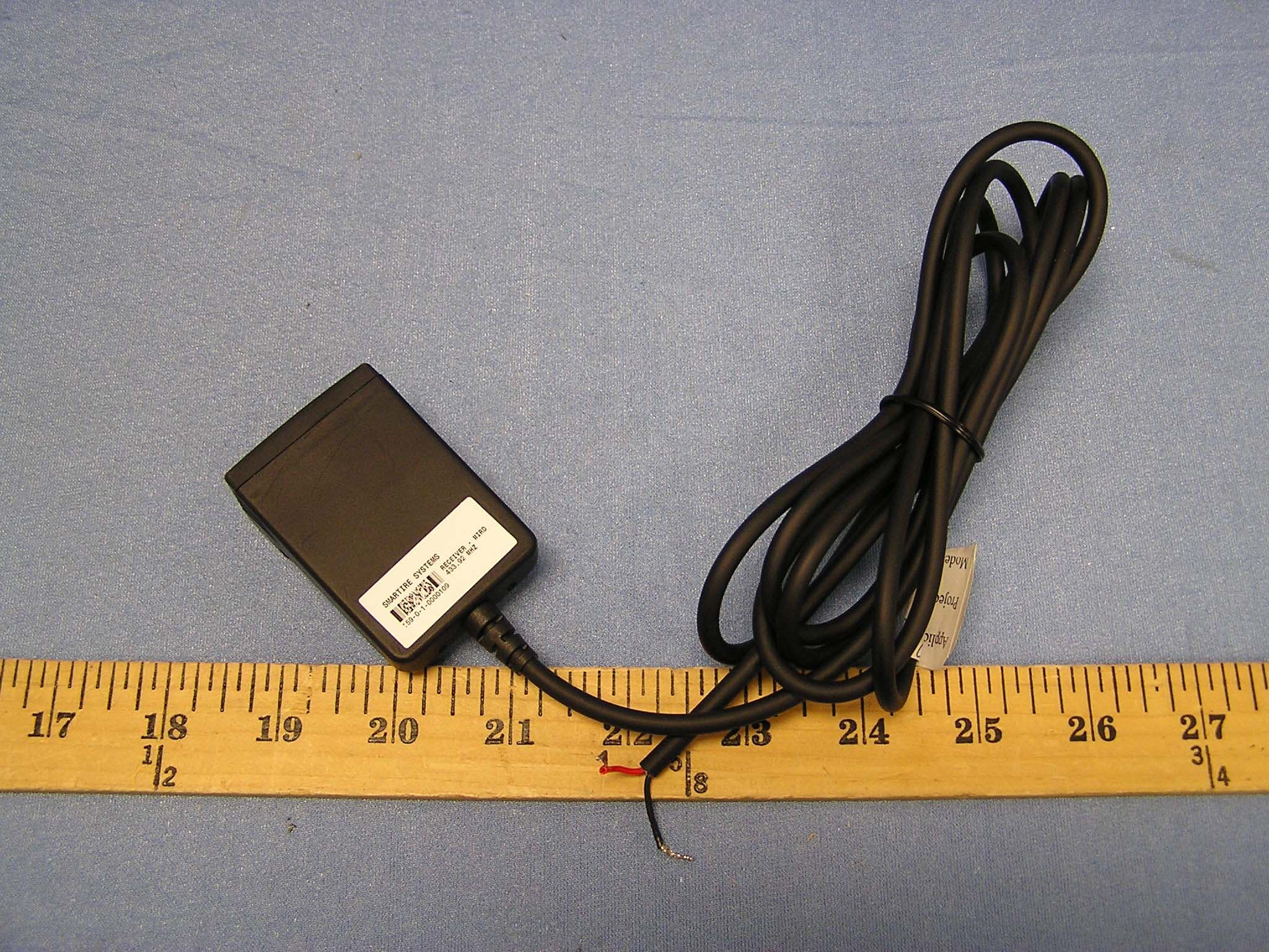
NATMIRD433
Jun 07, 2004433.92MHz Receiver
Equipment Class
CYY - Communications Receiver used w/Pt 15 Transmitter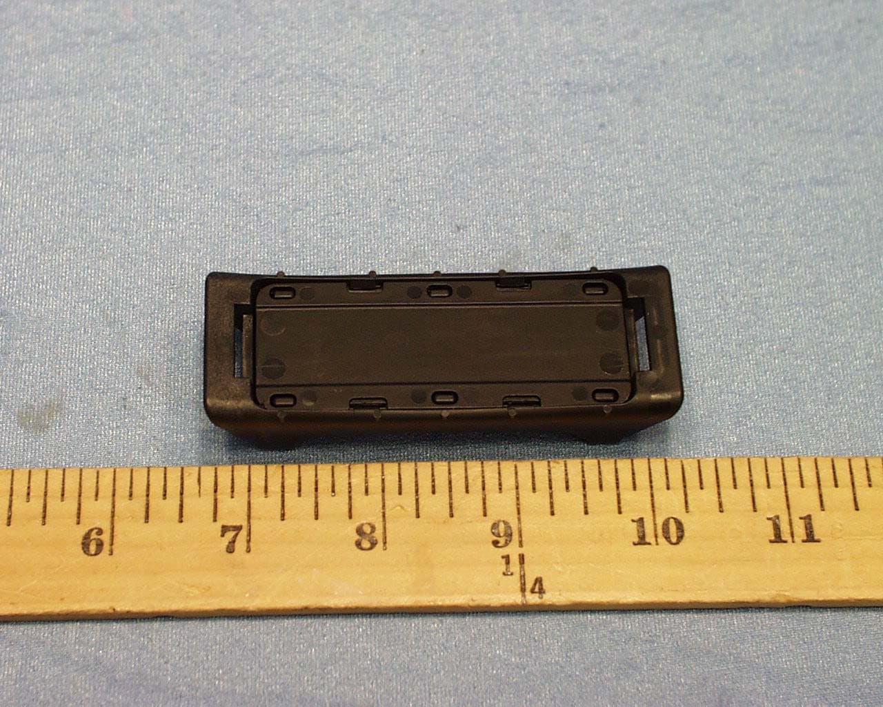
NATTX433CS-3
Jun 03, 2004Tire Monitoring Sensor
Equipment Class
DSC - Part 15 Security/Remote Control Transmitter
NATRX433-RV-1
Apr 09, 2003Tire Monitoring System-Display Receiver
Equipment Class
CYY - Communications Receiver used w/Pt 15 Transmitter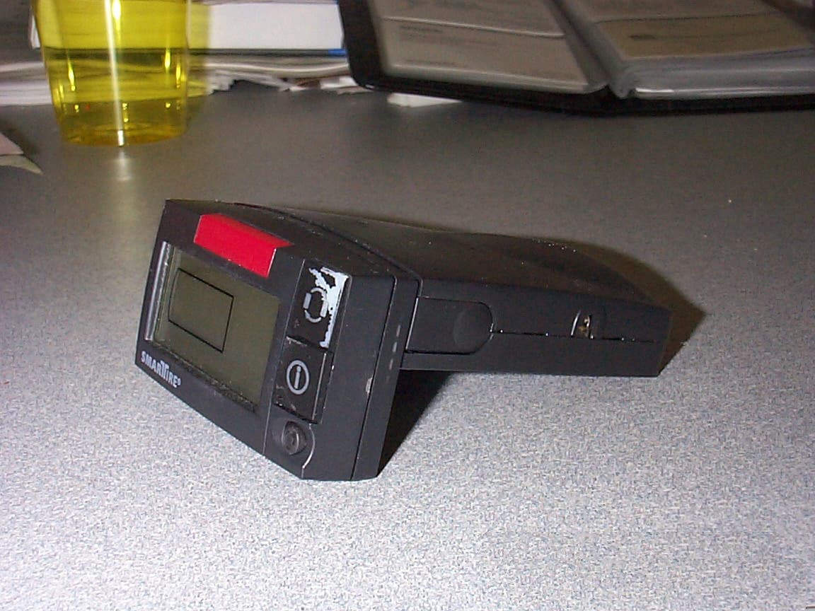
NATRX433R-2
Sep 16, 2001Receiver For a Wireless Tire Monitoring System
Equipment Class
CYY - Communications Receiver used w/Pt 15 Transmitter