NATTX433CS-3Tire Monitoring Sensor
Bendix Commercial Vehicle Systems LLC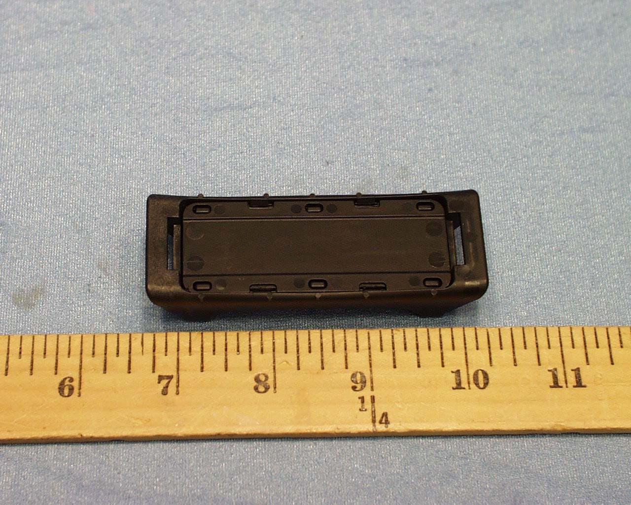
Click to zoom
Application Details
- Equipment Class
- DSC - Part 15 Security/Remote Control Transmitter
- Date of Grant
- Jun 03, 2004
- Application Purpose
- Original Equipment
- Date of Application
- Jun 03, 2004
- Equipment Note
- Tire Monitoring Sensor
- Frequency Range
- 433.92000000 - 433.92000000
- Country
- Canada
Documents & Files
Document Text
Text extracted from the exhibit documents filed with the FCC. Open a document above to read the original.
Users Manual
Dealer Stamp SmarTire Systems Inc. SmarTire Europe Limited Suite 150, 13151 Vanier Place Park 34 Richmond, British Columbia Didcot, Oxfordshire Canada, V6V 2J1 United Kingdom, OX11 7WB Tel: 1.604.276.9884 Tel: +44.1235.511010 Fax: 1.604.276.0864 Fax: +44.1235.514640 Email : [email protected] Email : [email protected] www.smartire.com www.smartire.com SMARTIRE HIGH PRESSURE TI RE MONITORING SYSTEM INSTALLATION INSTRUCTIONS 710.0016 13-Mar-04 Parts QTY Part number Description QTY Part number Description 1 200.0087 Receiver, Shielded 1 101.1060 Antenna Kit, 60’ 1 200.0068 Full Function Display (FFD) 1 101.1040 Antenna Kit, 40’ 4 200.0101 Transmitter - Strap Ts-2 1 101.1020 Antenna Kit, 20’ 4 264.0115 Strap - Stainless Steel Clamp 1 260.0157 FFD Cable 1 260.0158 Power Cable Note: Antennas purchased as required Technical Specifications Receiver Transmitter Input Supply 10 -18 vDC Power Consumption Normal = 480 mW, Max = 1.90 W Weight 454 g, (16.0 oz) 40 g (1.4 oz) Dimensions 102 x 117 x 38 mm (4.0 x 4.6 x 1.5 in.) 71 x 33 x 16 mm (2.8 x 1.3 x .63 in.) Operating Temperature -40 ºC to 85 ºC (-40 ºF x 185 ºF) -40 ºC to 125 ºC (-40 ºF x 257 ºF) Pressure Accuracy +/- 4.35 PSI (0.3 BAR) Maximum Cold Inflation Pressure 160 PSI (11.03 Bar) Maximum Operating Pressure 188 PSI (13.0 Bar) Battery Life 5 years at 48,000 km/yr (30,000 miles/yr) - approx. Factory Default Pressure Settings The default pressure settings can be customized to suit the application as required. Use the Full Function Display and follow the SmarTire FFD Manua l carefully to change the default settings if required. Cold Inflation Pressure 125 PSI Low Pressure Warning 110 PSI Pressure Deviation Alert 10 PSI High Temperature Warning 195 º F Warnings This tire monitoring system does not in any way re place the need for regular maintenance of the tire pressures and tire conditions. System Installation and Usage Use of the SmarTire® system requires that it has been properly installed and programmed by qualified personnel according to SmarTire Systems Inc. doc umentation. This includes the Owner’s Manual and any supplementary installation instructi ons included with system components. Use of Chemicals Temporary resealing or reinflation products containing internal sealers or propellants in any tire/wheel assembly may adversely affect the operation of the Sensor/Transmitters. Reacting to Alerts When an alert or warning condition is detected, reduce vehicle speed to an appropriate safe level and proceed to a safe stopping locati on or facility where the tire can be inspected and se rviced. The low pressure alert or warning indicates that the air pressure has dropped to a selected minimum. FCC NOTICE This device complies with Part 15 of the FCC Rules. Operat ion is subject to thefollowing two conditions: (1) this device may not cause harmful interference, and(2) this device must accept any interference received, including interference thatmay cause undesired operation.This equipment has been tested and found to comply with the limits for a Class Bdigital device, pursuant to Part 15 of the FCC Rules. These limits are designed toprovide reasonable protection against harmful interference in a re sidentialinstallation. This equipment generates, uses and can radiate radio frequency energyand, if not installed and used in accordan ce with the instructions, may cause harmfulinterference to radio communications. However, ther e is no guarantee thatinterference will not occur in a particular installation.If this equipment does cause harmful interference to radio or television reception,which can be determined by turning the equipment off and on, the user isencouraged to try to correct the interference by one or more of the followingmeasures:•R eorient or relocate the receiving antenna.•Increase the separation between the equipment and receiver.•Connect the equipment into an outlet on a circuit different from that to whichthe receiver is connected.•Consult the dealer or an experience d radio/TV technician for help.Changes or modifications to this device without the express approval of SmarTireSy stems Inc. may void the user’s authority to use this device. Installation of Transmitters 1. Slide the stainless steel straps through each of the Transmitters. 2. Dismount tire from wheel. 3. Position strap/Transmitter assembly around wheel at t he lowest point of the drop- center. See Figures 1 and 2. 4. The strap transmitter is to be positioned 3” from the worm gear 5. Position the Transmitter at the valve stem opening th en pull strap tight. Push in on the worm gear nut to hold the position. 6. Tighten with 5/16” nut driver or screwdriver until Transmitter is secure (35” pounds torque). 7. Cut excess strap leaving 1” past the worm gear. 8. Mount tire being careful not to pinch the Transmitter with the bead of the tire. 9. Balance the tire. 10. Mount the tire on the vehicle. Testing the System 1. Turn on the ignition switch and verify that t he Receiver beeps three times and the FFD turns on. 2. Reduce the air in a tire to 3 PSI below the alert level (15 PSI or 1.03 BAR), and verify that the warning light of the FFD turns on. 3. Re-inflate the tire. 4. Repeat steps 2 and 3 for remaining tire positions. 5. In cases where the settings are not appropriate to the installation, use the FFD manual to program the system to the desired settings. Figure 5 – System wiring Red to positive Black to ground Optional antennas Receiver Full Function Display Power Cable Installation of Receiver and Full Function Display 1. Install the antenna according to instructions in the antenna kit. 2. Find a suitable location for the Receiver and Full Function Display assembly. The Receiver is normally installed behind the dashboard. The Full Function Displ ay is assembled somewhere on or in the dashboard. 3. Wire the system as shown in Figure 5. Plug the Full Function Display into the left plug of the Receiver. Plug the power cable into right side plug. 4. The red wire of the power …
Text truncated - open the document above for the full version.
Cover Letter(s)
X:\Projects\200-0101-CS-2\FCC\Request for Confidentiality.doc SmarTire Systems Inc. Suite 150, 13151 Vanier Place Richmond, British Columbia Canada, V6V 2J1 T: 604.276.9884 F: 604.276.2350 www.smartire.com SMTR: OTCBB Date: March 29, 2004 Federal Communications Commission Equipment Authorization branch 7435 Oakland Mills Road Columbia, MD 21046 Re: Request for Confidentiality Gentlemen: In reference to the application under FCC ID NATTX433CS-3 ,and pursuant to Sections 0.457(d)(l)(ii) and 0.459 of the Commission’s Rules, the Applicant hereby requests confidential treatment of the accompanying information as outlined below: Schematics Block Diagrams Technical Description These documents contain detailed system and equipment description and related information about the product that SmarTire Systems Inc. considers to be proprietary, confidential, and a custom design and, otherwise, would not release to the general public. Since this design is a basis from which future technological products will evolve, SmarTire Systems Inc. considers that this information would be of benefit to its competitors, and that disclosure of the information in these documents would give competitors an unfair advantage in the market. Sincerely, Robert G. Patterson Senior RF Engineer SmarTire Systems Inc. X:\Projects\200-0101-CS-2\FCC\Request for Confidentiality.doc
ID Label/Location Info
PROPOSED FCC ID LABEL AND LOCATION SMARTIRE SYSTEMS INC. This device complies with Part 15 of the FCC Rules. Operation is subject to the following two conditions: (1) this device may not cause harmful interference, and (2) this device must accept any interference received, including interference that may cause undesired operation. FCC ID: NATTX433CS-3 FCC ID LABEL
Test Report
FCC PART 15 SUBPART C CERTIFICATION REPORT FOR 433.92 MHz COMMERCIAL SENSOR MODEL: 200.0101.R FCC ID NO: NATTX433CS-3 REPORT NO: 04U2651-1 ISSUE DATE: APRIL 6, 2004 Prepared for SMARTIRE SYSTEMS INC. #150 13151 VANIER PLACE RICHMOND, BC CANADA Prepared by COMPLIANCE ENGINEERING SERVICES, INC. d.b.a. COMPLIANCE CERTIFICATION SERVICES 561F MONTEREY ROAD MORGAN HILL, CA 95037 USA TEL: (408) 463-0885 FAX: (408) 463-0888 REPORT NO: 04U2651-1 DATE: APRIL 6, 2004 EUT: 433.92 MHz COMMERCIAL SENSOR FCC ID: NATTX433CS-3 COMPLIANCE CERTIFICATION SERVICES CCS DOCUMENT NO:CCSUP4020B 561F MONTEREY RD., MORGAN HILL, CA 95037, USA TEL:(408)463-0885 FAX:(408)463-0888 This report shall not be reproduced except in full, without the written approval of CCS. This document may be altered or revised by Compliance Certification Services personnel only, and shall be noted in the revision section of the document. TABLE OF CONTENTS PAGE 1. VERIFICATION OF COMPLIANCE....................................3 2. PRODUCT DESCRIPTION...........................................4 3. TEST FACILITY..................................................4 4. MEASUREMENT STANDARD........................................4 5. TEST METHODOLOGY............................................4 6. MEASUREMENT EQUIPMENT USED..................................4 7. POWERLINE RFI LIMIT............................................5 8. RADIATED EMISSION LIMITS.......................................5 9. SYSTEM TEST CONFIGURATION.....................................6 10. TEST PROCEDURE...............................................7 11. EQUIPMENT MODIFICATIONS......................................8 12. TEST RESULT..................................................9 12. TEST RESULT..................................................9 12.1 MAXIMUM MODULATION PERCENTAGE (M%)........................9 12.2 EMISSION BANDWIDTH..........................................9 TEST DATA • Maximum Modulation Percentage Plot • Emission Bandwidth Plot • Radiated Emission Worksheet for Peak Measurement • Radiated Emission Worksheet for Average Measurement ATTACHMENT • EUT Photographs • Proposed FCC ID Label • Schematics & Block Diagram • User Manual REPORT NO: 04U2651-1 DATE: APRIL 6, 2004 EUT: 433.92 MHz COMMERCIAL SENSOR FCC ID: NATTX433CS-3 Page 3 of 17 COMPLIANCE CERTIFICATION SERVICES CCS DOCUMENT NO:CCSUP4020B 561F MONTEREY RD., MORGAN HILL, CA 95037, USA TEL:(408)463-0885 FAX:(408)463-0888 This report shall not be reproduced except in full, without the written approval of CCS. This document may be altered or revised by Compliance Certification Services personnel only, and shall be noted in the revision section of the document. 1. VERIFICATION OF COMPLIANCE COMPANY NAME : SMARTIRE SYSTEMS INC. #150, 13151 VANIER PLACE RICHMOND BC, CANADA EUT DESCRIPTION : 433.92 MHz COMMERCIAL SENSOR MODEL NO : 200.0101.R FCC ID : NATTX433CS-3 DATE TESTED : 4-5-2004 REPORT NUMBER : 04U2651-1 TYPE OF EQUIPMENT COMMERCIAL SENSOR EQUIPMENT TYPE 433.92MHz TRANSMITTER MEASUREMENT PROCEDURE ANSI C63.4 / 2001 LIMIT TYPE CERTIFICATION FCC RULE CFR 47, PART 15 The above equipment was tested by Compliance Certification Services for compliance with the requirements set forth in the FCC CFR 47, PART 15. The results of testing in this report apply to the product/system which was tested only. Other similar equipment will not necessarily produce the same results due to production tolerance and measurement uncertainties. Warning : This document reports conditions under which testing was conducted and results of tests performed. This document may not be altered or revised in any way unless done so by Compliance Certification Services and all revisions are duly noted in the revisions section. Any alteration of this document not carried out by Compliance Certification will constitute fraud and shall nullify the document. Tested By: CHIN PANG EMC TECHNICIAN COMPLIANCE CERTIFICATION SERVICES Approved & Released By: THU CHAN EMC SUPERVISOR COMPLIANCE CERTIFICATION SERVICES REPORT NO: 04U2651-1 DATE: APRIL 6, 2004 EUT: 433.92 MHz COMMERCIAL SENSOR FCC ID: NATTX433CS-3 Page 4 of 17 COMPLIANCE CERTIFICATION SERVICES CCS DOCUMENT NO:CCSUP4020B 561F MONTEREY RD., MORGAN HILL, CA 95037, USA TEL:(408)463-0885 FAX:(408)463-0888 This report shall not be reproduced except in full, without the written approval of CCS. This document may be altered or revised by Compliance Certification Services personnel only, and shall be noted in the revision section of the document. 2. PRODUCT DESCRIPTION Fundamental Frequency 433.92 MHz Power Source 3V Battery Transmitting Time Interval: 3-5 minutes; Length: 500ms Associated Receiver NA Manufacturer Smartire Systems Inc. 3. TEST FACILITY The 3/10/30 meter open area test site and conducted measurement facility used to collect the radiated data is located at 561F Monterey Road, Morgan Hill, California, U.S.A. A detailed description of the test facility was submitted to the Commission on May 27,1994. 4. MEASUREMENT STANDARD The site is constructed and calibrated in conformance with the requirements of ANSI C63.4/2001. 5. TEST METHODOLOGY For an intentional radiator, the spectrum shall be investigated from the lowest radio frequency signal generated in the device, without going below 9 KHz, up to at least the tenth harmonic of the highest fundamental frequency or to 40 GHz, whichever is lower. (CFR 47 Section 15.33) 6. MEASUREMENT EQUIPMENT USED TEST EQUIPMENT LIST Name of EquipmentManufacturerModel No.Serial No.Due Date EMI Receiver, 9 kHz ~ 2.9 GHzHP8542E3942A0028611/21/2004 RF Filter SectionHP85420E3705A0025611/21/2004 Bilog AntennaSunol SciencesJB1 AntennaA12100312/22/2004 Amplifier 1-26GHzMITEQNSP2600-SP9243414/25/2004 Spectrum Analyzer, 26.5 GHzHP8593EM3710A0020510/1/2004 Antenna, Horn 1 ~ 18 GHzEMCO31172931012/26/2004 Spectrum Analyzer AgilentE4446AMY433601121/13/2005 REPORT NO: 04U2651-1 DATE: APRIL 6, 2004 EUT: 433.92 MHz COMMERCIAL SENSOR FCC ID: NATTX433CS-3 Page 5 of 17 COMPLI…
Text truncated - open the document above for the full version.
Test Setup Photos
REPORT NO: 04U2651-1 DATE: APRIL 6, 2004 EUT: 433.92 MHz COMMERCIAL SENSOR FCC ID: NATTX433CS-3 Page 6 of 17 COMPLIANCE CERTIFICATION SERVICES CCS DOCUMENT NO:CCSUP4020B 561F MONTEREY RD., MORGAN HILL, CA 95037, USA TEL:(408)463-0885 FAX:(408)463-0888 This report shall not be reproduced except in full, without the written approval of CCS. This document may be altered or revised by Compliance Certification Services personnel only, and shall be noted in the revision section of the document. 9. SYSTEM TEST CONFIGURATION Use a block of foam and combined it with EUT wrapping rubber band around it. This way it can test X.Y, and Z axis. To activate continuous transmission, place a small plastic block between rubber band and EUT push button. Radiated Open Site Test Set-up X-Axis Y-Axis Z-Axis
Contact Information
Applicant
Robert Patterson(RF Engineer)
Test Firm
Compliance Certification Services IncSteve Cheng
Technical Specifications
| # | Rule Parts | Frequency Range | Power Output |
|---|---|---|---|
| 1 | 15.231(e) | 433.92 MHz - 433.92 MHz | - |
Other Applications from Bendix Commercial Vehicle Systems LLC
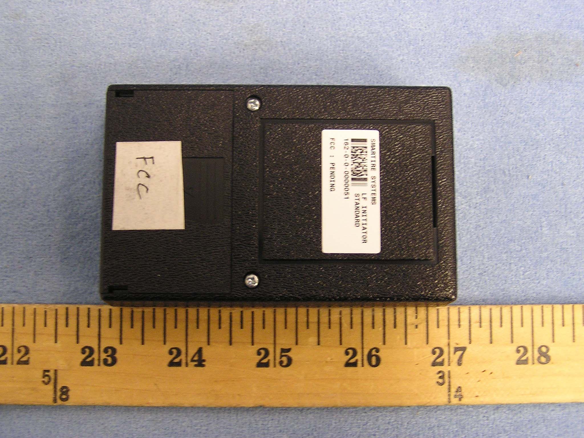
NATLF0162
Jan 06, 2005LF Initiation Tool, 125 kHz LF Transmitter
Equipment Class
DCD - Part 15 Low Power Transmitter Below 1705 kHz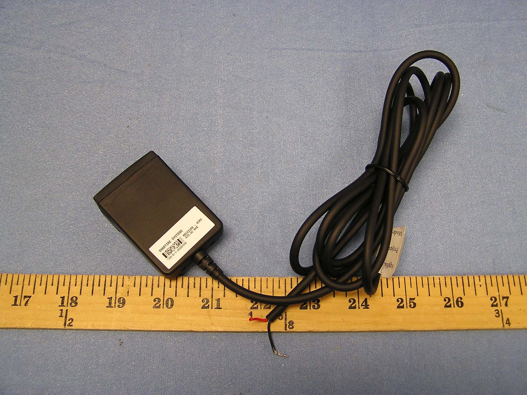
NATMIRD433
Jun 07, 2004433.92MHz Receiver
Equipment Class
CYY - Communications Receiver used w/Pt 15 Transmitter
NATRX433-RV-1
Apr 09, 2003Tire Monitoring System-Display Receiver
Equipment Class
CYY - Communications Receiver used w/Pt 15 Transmitter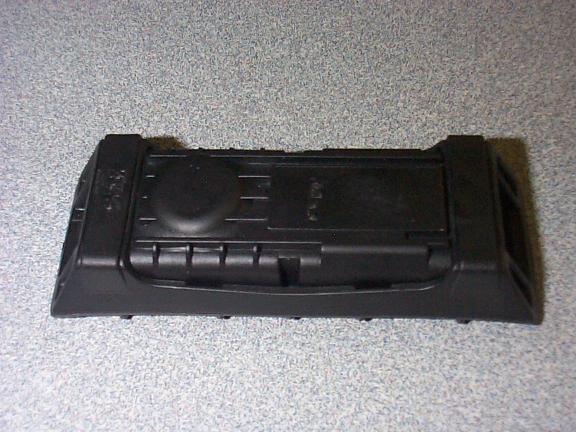
NATTX433CS-2
Apr 08, 2003Tire Monitoring Sensor
Equipment Class
DSR - Part 15 Remote Control/Security Device Transceiver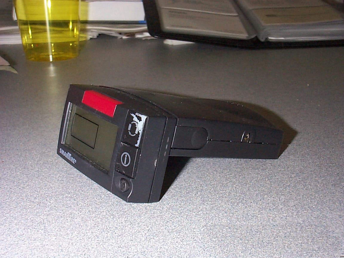
NATRX433R-2
Sep 16, 2001Receiver For a Wireless Tire Monitoring System
Equipment Class
CYY - Communications Receiver used w/Pt 15 Transmitter