NATRX433R-2Receiver For a Wireless Tire Monitoring System
Bendix Commercial Vehicle Systems LLC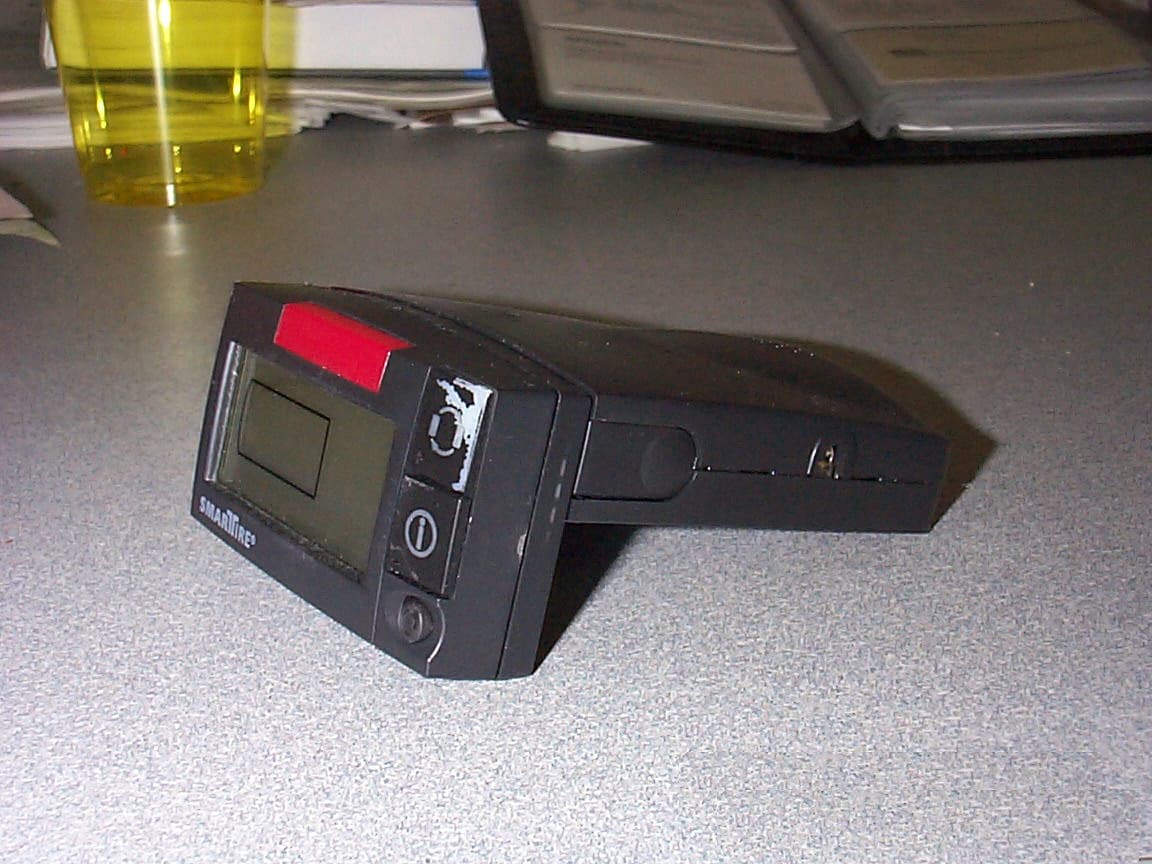
Click to zoom
Application Details
- Equipment Class
- CYY - Communications Receiver used w/Pt 15 Transmitter
- Date of Grant
- Sep 16, 2001
- Application Purpose
- Original Equipment
- Date of Application
- Aug 14, 2001
- Equipment Note
- Receiver For a Wireless Tire Monitoring System
- Frequency Range
- 433.92000000 - 433.92000000
- Country
- Canada
Documents & Files
Document Text
Text extracted from the exhibit documents filed with the FCC. Open a document above to read the original.
Users Manual
SmarTire Systems Inc. Tire Monitoring System Reference Manual 6/13/2000 Page 1 of 55 This manual is under review by SmarTire – DO NOT ISSUE Draft Tire Monitor System Reference Manual GENII Draft Note; Prior to issue this manual to be examined and approved by; Engineering Marketing Customer Service SmarTire Systems Inc. Tire Monitoring System Reference Manual 6/13/2000 Page 2 of 55 This manual is under review by SmarTire – DO NOT ISSUE Table of Contents FCC Notice.....................................................................................................................5 Introduction....................................................................................................................6 Purpose of Manual................................................................................................................6 About Tire Monitoring Systems...........................................................................................6 Feature Summary..........................................................................................................................................7 System Scope of Use and Warnings......................................................................................8 The SmarTire™ System and Tire Maintenance..............................................................................................8 System Installation and Usage.......................................................................................................................8 Use of Chemicals..........................................................................................................................................8 Power Connection.........................................................................................................................................8 Warnings......................................................................................................................................................8 SmarTire Product Overview........................................................................................10 Product List.........................................................................................................................10 Tire Monitor System Kit Component Table......................................................................11 System Descriptions............................................................................................................12 Pressure Alert Systems – 2 and 4 wheels – Multi-fit Strap Mount Transmitters.............................................12 Overview................................................................................................................................................12 Bill of Materials.....................................................................................................................................13 Component Images.................................................................................................................................14 Pressure Alert Systems – 2 and 4 wheels – Multi-fit Valve Mount Transmitters............................................15 Overview................................................................................................................................................15 Bill of Materials.....................................................................................................................................16 Component Images.................................................................................................................................17 Pressure Alert Full Function Display...........................................................................................................18 Overview................................................................................................................................................18 Bill of Materials.....................................................................................................................................19 Component Images.................................................................................................................................19 Pressure Alert Flexible Power Adaptor........................................................................................................20 Overview................................................................................................................................................20 Bill of Materials.....................................................................................................................................20 Component Image..................................................................................................................................20 Pressure Alert Transmitter Kit – 2 - Multi-fit Strap Mount Transmitters.......................................................21 Overview................................................................................................................................................21 Bill of Materials.....................................................................................................................................21 Component Image..................................................................................................................................21 Pressure Alert Transmitter Kit – 2 - Multi-fit Valve Mount Transmitters......................................................22 Overview................................................................................................................................................22 Bill of Materials.....................................................................................................................................22 Component Image...........................................................................................................…
Text truncated - open the document above for the full version.
Attestation Statements
Applicant: SmarTire Systems, Inc.FCC ID: NATRX433R-2 Exhibit II FCC Certification Report for the FCC ID: NATRX433R-2 UHF RECEIVER New Certification Exhibit II. Certification Data
Cover Letter(s)
Applicant: SmarTire Systems, Inc.FCC ID: NATRX433R-2 Exhibit 13 EXHIBIT XIII. Cover Letter FCC Certification Report for the FCC ID: NATRX433R-2 SmarTire Systems, Inc. Tire Monitoring System Receiver Family Certification Applicant: SmarTire Systems, Inc.FCC ID: NATRX433R-2 Exhibit 13 August 18, 2001 Federal Communications Commission Authorization and Evaluation Division 7435 Oakland Mills Rd. Columbia, MD 21046 Re: FCC ID: NATRX433R-2 Grantee: SmarTire Systems, Inc. Model: RX433R-2 Basic Receiver, High End Display Receiver and High End Remote Display Receiver Subject: Receiver Certification Application Gentlemen: On behalf of SmarTire Systems, Inc., of Richmond, British Columbia, we request Certification for the above referenced receiver family under the FCC ID: NATRX433R-2. The equipment would be eligible under Part 2.924, Marketing of electrically identical equipment having multiple trade names and model numbers or type numbers under the same FCC Identifier, as no changes are made to the receiver in the three versions. Thank you for your time and consideration of this application. Please contact the undersigned should you require any additional technical or non-technical information concerning this request for Certification. Sincerely, Rod Munro President Spectrum Technology, Inc. Email: [email protected] Project: Confidential Date: July 25, 2001 Page 1 of 1
External Photos
Applicant: SmarTire Systems, Inc.FCC ID: NATRX433R-2 EXHIBIT 3 EXHIBIT 3 EXTERNAL PHOTOS Basic Receiver Photo 1 Basic Receiver front view Photo 2 Basic Receiver back view Photo 3 Basic Receiver top side view Photo 4 Basic Receiver bottom side view Photo 5 Basic Receiver on gooseneck bottom side view High End Display Photo 6 High End Display Receiver front view Photo 7 High End Display Receiver quatering view High End Remote Display Receiver Photo 8 High End Remote Display Receiver front view Photo 9 High End Remote Display Receiver quartering view
ID Label/Location Info
THIS INFORMATION IS PROPRIETARY AND MUST NOT BE COPIED AND/OR REVEALED TO THIRD PARTIES WITHOUT THE WRITTEN CONSENT OF SMARTIRE SYSTEMS INC. Title: Drawn C.LIBERA Checked SPECIFICATION: LABEL DWG NO. 269.0119.08-AD DL-xxxx RELREV DESCRIPTIONDATEINIT Designer C.LIBERA Manager S.LAMMERS 3-AUG-01 CLOriginal 10 ProtoPilotProduction 2001 SmarTire Systems Inc. #150-13151 Vanier Place, Richmond, British Columbia V6V 2J1 PAGE 1 Regulatory Label Label Stock code 269.0119.08 Regulatory Label Label position on back of receiver PATENTS 5,231,8725,285,189 5,335,5405,559,484 SmarTire Systems Inc.. RECEIVER 433.92 MHZ 059-1-1-0000001 SmarTire Systems SmarTire Systems 10R-020-362 10R-020-362 11 11 E E 11 11 FCC ID: NATRX433R-2 FCC ID: NATRX433R-2 CAN: 3323104167A CAN: 3323104167A
ID Label/Location Info
Applicant: Smartire Systems, Inc . FCC ID: NATRX433R-2 Exhibit 1 LIST OF EXHIBITS DESCRIPTION EXHIBITSREFERENCE I.Identification label Information12.1033 (b) 7 & 2.925 & General Information1A2.1033 (b) 1, 2, 8 II.Certification Data2 III.External Photographs32.1033 (b) 7 IV.Block Diagrams (Circuit Diagrams)42.1033 (b) 4, 5 V. Schematic Diagrams & Antenna Assembly 52.1033 (b) 4 VI.Test Report 6 2.1033 (b) 6 VII.Test Set-up Procedures7 2.1041 VIII.Instruction Manual 82.1033 (b) 3 IX.Internal Photographs 92.1033 (b) 7 X.Part List and Tune Up Procedures10 XI.RF Exposure Information11 2.1093 N/A XII.Operational Description12 *2.1033 (b) 4 XIII. Cover Letter, Action Requested13 Cover Letter, Request for Confidentiality13 Cover Letter, Agent Authorization13 * Description contained in Exhibit 4 Applicant: Smartire Systems, Inc . FCC ID: NATRX433R-2 Exhibit 1 EXHIBIT 1. ITEM 1. IDENTIFICATION LABEL ----- 47 CFR 2.1033(C) 11 FCC ID LABEL LOCATION On the back side of the receiver unit enclosure. Please see drawing on the accompanying page. MARKINGS (TEXT) Enlarged view of the FCC Identifier portion of label on the accompanying page: Applicant: Smartire Systems, Inc . FCC ID: NATRX433R-2 Exhibit 1 Item 1A. General Information Information required by Section 2.1033(b) 1, 2, 8. 1. The Applicant is:SmarTire Systems, Inc. #150 Vanier Place Richmond, BC V6V 2J1 Canada The Manufacturer is: Aimtronics 8128 River Way Delta, British Columbia V4G 1K5 2. FCC ID: NATRX433R-2 3. Frequency Range: 433.92 MHz +/- 75 kHz 4. The receiver was tested in all three of the family configurations. 1.) the Basic Receiver 2.) the High End Display Receiver 3.) the High End Remote Display Receiver (this version has an interconnecting cable between the receiver and the display) No peripheral I/O’s are available on the receivers other than the Remote Display Cable. 5. (1.) Production Plans Part 2.1031 Quantity Productions is Planned Application References N/A Data submittal Procedure Electronic Filing
Internal Photos
Applicant: SmarTire Systems, Inc.FCC ID: NATRX433R-2 EXHIBIT 9 EXHIBIT 9 INTERNAL PHOTOS Photo 1 Top side of Receiver PCB Photo 2 Bottom side of Receiver PCB Photo 3 Front LCD display PCB Photo 4 Back of LCD display Photos 1 & 2 show the Basic Receiver Photos 1 – 4 show High End Display and High End Remote Display Receivers
RF Exposure Info
Applicant: SmarTire Systems, Inc. FCC ID:NATRX433R-2 Exhibit 11 RF EXPOSURE INFORMATION This receiver is NOT subject to the provisions of 47 CFR 2.1091 for routine environmental evaluation for RF exposure.
Test Report
EXHIBIT 6 Application for Receiver CERTIFICATION Under CFR Title 47, Part 15.109 GRANTEE: SmarTire Systems, Inc. FCC ID: NATRX433-2 August 14, 2001 Prepared By: Spectrum Technology, Inc. 209 Dayton Street Edmonds, WA 98020 425 771-4482 APPLICATION FOR CERTIFICATION TABLE OF CONTENTS Field Strength of Radiated Emissions Discussion Part 15.109(a) 1 - 2 Receiver Antenna Power Conduction Part 15.111 N/A TEST: FIELD STRENGTH OF RADIATED EMISSIONS Grantee:SmartTire Systems, Inc. FCC ID: NATRX433-2 Setup: The equipment under test (EUT) was configured and operated in accordance with the applicable provisions of ANSI C63.4-1992, Section 6, 12. Measurements were made in accordance with applicable paragraphs of Section 8.2.2 and 8.2.3, Section 12.1.1.1 Appendix D, Section 12.1.4 and Appendix H3 and H4. The EUT was placed on a 1 by 1.5 meter table located 40 cm above a 2-meter diameter non-metallic turntable that sits 40 cm above the 15 X 30 meter ground plane at Spectrum's Open Area Test Site. The bi-conical or log-periodic antenna was mounted on a tower spaced at a three meters distance, and arranged for adjustment in height (1-4 meters) and vertical/horizontal polarization to maximize the emissions levels when combined with turntable rotation of the EUT. The dual ridged guide antenna was mounted on a tripod at one-meter height and adjusted for vertical or horizontal antenna orientation. A HP 8562A spectrum analyzer with a HP 8447F, Option H64 amplifier and a HP 83006A pre-amplifier were used for the peak measuring instrumentation. Discussion: No modifications were required prior to the final radiated emissions measurements reported herein. The EUT is a 433 MHz receiver used in the SmartTire Passenger Car Tire Monitoring System. One of the three versions of the receiver would be installed in a passenger vehicle and used to receive signals and display status of passenger tire pressure sensors installed on the wheels. All three version of receiver use the identical receiver board. The Basic Receiver has LED’s to display status while the High End Display and High End Remote Display versions both have a identical LCD Display connected either directly or remotely via a cable to the Basic Receiver. A transmitter/ sensor would be installed either on the rim or in place of the valve for each wheel depending on the model of transmitter. Each transmitter reports back to the receiver with pressure status and temperature status regardless of vehicle movement. If a change in excess of 1 lb is detected the 4 to 6 minute normal cycle transmit interval is interrupted. The information is transmitted immediately, being considered a safety issue, as in the case of a punctured tire and treated accordingly. The receiver was powered with a 12-volt external power supply connected to the cigarette lighter plug connector. Page 1 Preliminary measurements were made as described in Section 8.3.11 and 13.1.4.1 with the receiver operating as described. During preliminary measurements only two emissions of significance were detected with the receive antenna in close proximity to the EUT. The low level of the second harmonic and broadband energy observed at six inches was not measurable at 3 meters even with the use of an amplifier. The EUT configuration is detailed in the photographs included with this report. The final set of measurements as specified in Section 8.3.1.2 and 13.1.4.2 were made as specified in Section 13.1.1. The receiver was observed while positioned in three mutually orthogonal planes with the horizontal position "on its back antenna parallel to ground plane", the worst case. The EUT’s cigarette lighter plug 12 VDC power cord and remote cable (for the one version) were manipulated to different positions endeavoring to raise emission levels. The 12 Volt source was an Astron VS-35-M power supply during the measurements. RBW and VBW of 100 kHz were used for measurements below 1 GHz. Above 1 GHz peak measurements were made with a RBW and VBW of 1 MHz. We also endeavored to maximize levels of the emissions with EUT rotation and adjustment of antenna height. Measurements were made over the frequency range of 30 - 5000 MHz. A HP 8447F pre- amplifier was used during these measurements. The receiver operating at its nominal 433.92 MHz. A transmitter/sensor was activated to ensure receiver operation via observing the display, then deactivated. No receiver emissions were measurable at 3 meters with the use of a preamp so the antenna was moved in to 1 meter and still no emissions were measurable for any of the three versions. We specifically looked for the LO and harmonics in detail. Measurements were made on all three packaging versions of the receiver, the Basic Receiver, the High End Display and High End Remote Display versions with the LCD Display connected either directly or remotely to the Basic Receiver. No receiver antenna conducted emissions measurements were made due to the permanent antenna. The antenna type is a PCB mounted coil antenna. Conclusion: The SmarTire Systems, Inc., FCC ID: NATRX433-2, when operated and measured as discussed above, meets the receiver radiated spurious emissions requirements under Title 47, CFR Part 15.109(a). This receiver is not subject to the transition provisions of Part 15.37. Page 2
Test Setup Photos
VII. Test Set-Up Procedures BLOCK DIAGRAM #1 Receiver Radiated Spurious Emissions Test Set Up D = 100 ft. or 3 meters │ │1/2 Wave Dipole * │ │ │ D │ ├──────────────────┼────┐ │ │ │ │ │ │ │ │ │ │ │ │ │ │ │ ┌────────┴─────────┐ │ │ │ │ │ Equipment │ │ │ Under Test │ │ │ │ │ └──────────────────┘ │ │ │ │ ┌────────────────┐ │ │ │ │ │ Spectrum │ └────────┤ Analyzer │ │ │ │ │ └────────────────┘ See Equipment List for Equipment Specifications *1/2 Wave Dipole 30-1000 MHz Dual Ridged Guide Antenna or Broadband Log Periodic 1-10 GHz TEST EQUIPMENT LIST A SPECTRUM TECHNOLOGY, INC. EquipmentManufacturerSerial NumberCal Date/Due Date Spectrum AnalyzerHewlett-Packard 8562A08562-6006211/15/00 11/15/01 AmplifierHewlett-Packard 8447F2727A02208 11/15/00 11/15/01 9 kHz-1300 MHz OPT H64 Service MonitorIFR FM/AM 500A4103--- OscilloscopeKikusui C0550606132295--- Power SupplyAstron VS358601266--- VoltmeterFluke 8020AN2420658 --- MultimeterFluke 253710310--- WattmeterBird 4356227 --- RF TerminationBird 813510004--- Dual Phase LISN STI per MP-402 1/10/01 1/10/02 50 ohm/50 uH Dual Phase LISNCompliance Design8012-50R-24-BNC 1/10/01 1/10/02 50 ohm/50 uH Audio GeneratorHewlett-Packard 205-AG 8689--- ThermometerFluke 523965185--- Test LineSimulator, Teltone TLS-2 none--- Turn Table, RCEMCO 1060-2M8912-1415--- Antenna Mast, RCCompliance Design, Inc. M100--- Antennas: Dipole SetEMCO Model: 3121C133509/16/0003/16/02 Dipole Set EMCO Model: 3121C133609/16/0003/16/02 Bi-ConicalEMCO 3104 3763reference only Bi-Conical EMCO 3104C9401-463501/25/0101/25/02 Log-PeriodicEMCO 3146 175401/25/0101/25/02 BiConiLogEMCO 3141112504/27/0104/27/02 Active LoopEMCO 65029107-2645reference only Rev. 05/01 Page 2 Photos of EUT at OATS facility follow: 1. Basic Receiver Front View 2. Basic Receiver Rear View
Contact Information
Applicant
Robert Patterson(RF Engineer)
Technical Contact
Spectrum Technology IncRod Munro
[email protected]425 771-4482
209 Dayton Street · Edmonds, Washington · United States
Non-Technical Contact
Spectrum Technology IncRod Munro
[email protected]425 771-4482
Test Firm
Spectrum Technology Inc.Rod Munro
Technical Specifications
| # | Rule Parts | Frequency Range | Power Output |
|---|---|---|---|
| 1 | 15B | 433.92 MHz - 433.92 MHz | - |
Other Applications from Bendix Commercial Vehicle Systems LLC
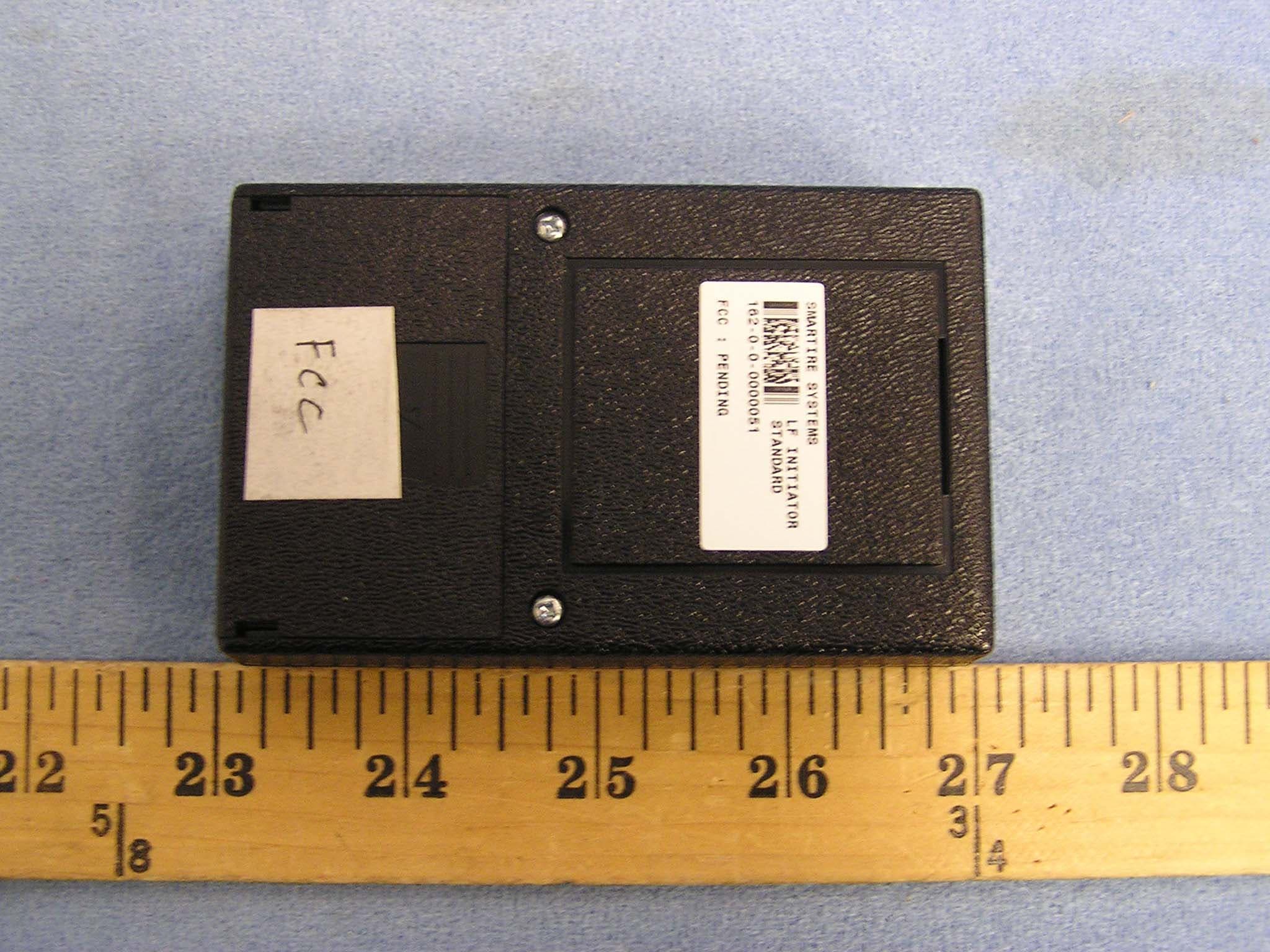
NATLF0162
Jan 06, 2005LF Initiation Tool, 125 kHz LF Transmitter
Equipment Class
DCD - Part 15 Low Power Transmitter Below 1705 kHz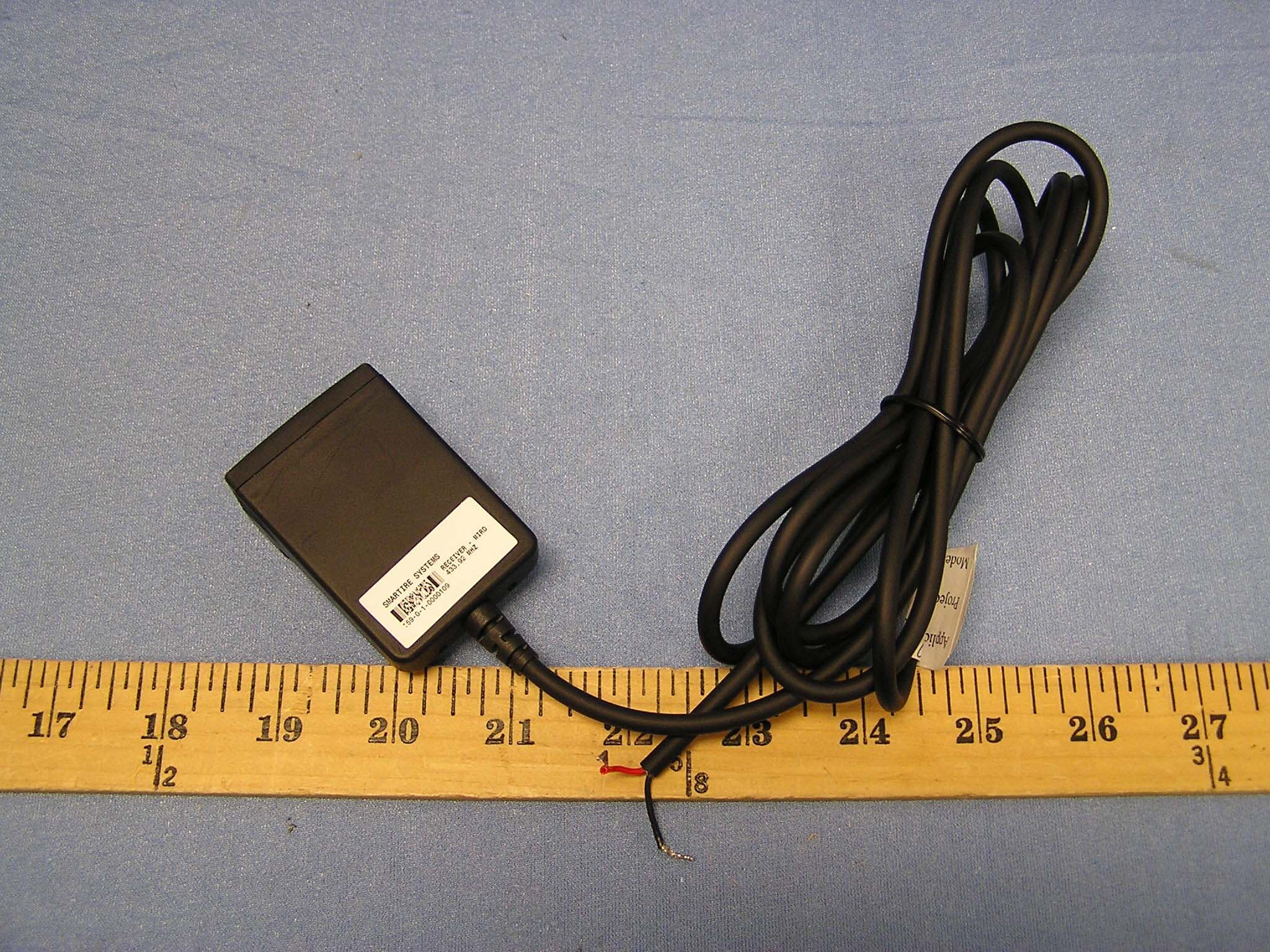
NATMIRD433
Jun 07, 2004433.92MHz Receiver
Equipment Class
CYY - Communications Receiver used w/Pt 15 Transmitter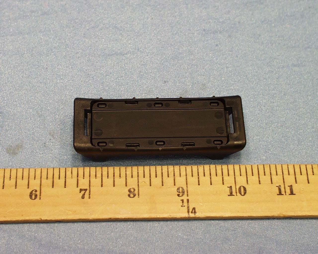
NATTX433CS-3
Jun 03, 2004Tire Monitoring Sensor
Equipment Class
DSC - Part 15 Security/Remote Control Transmitter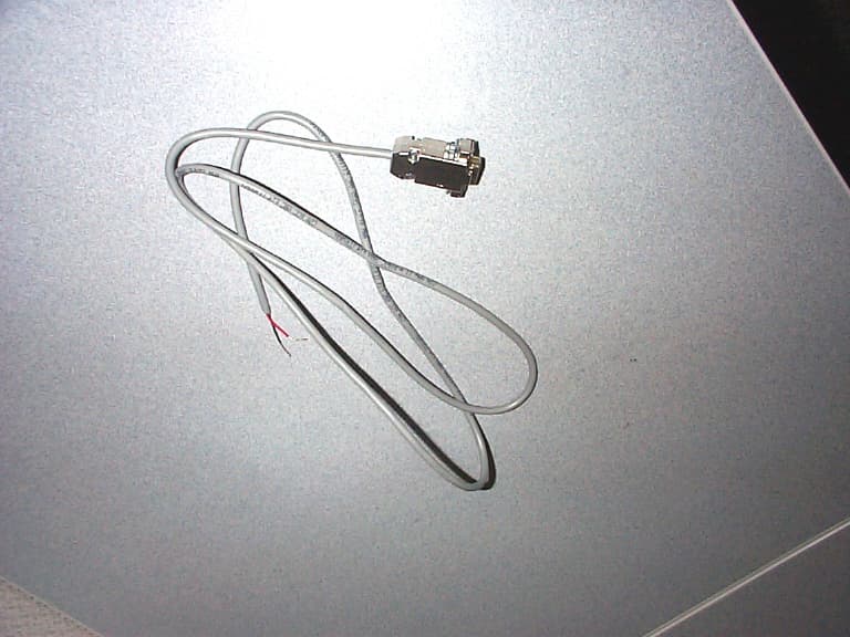
NATRX433-RV-1
Apr 09, 2003Tire Monitoring System-Display Receiver
Equipment Class
CYY - Communications Receiver used w/Pt 15 Transmitter
NATTX433CS-2
Apr 08, 2003Tire Monitoring Sensor
Equipment Class
DSR - Part 15 Remote Control/Security Device Transceiver