NATTX355MSRim Mount Transmitter for the SmarTire Signal Pass
Bendix Commercial Vehicle Systems LLC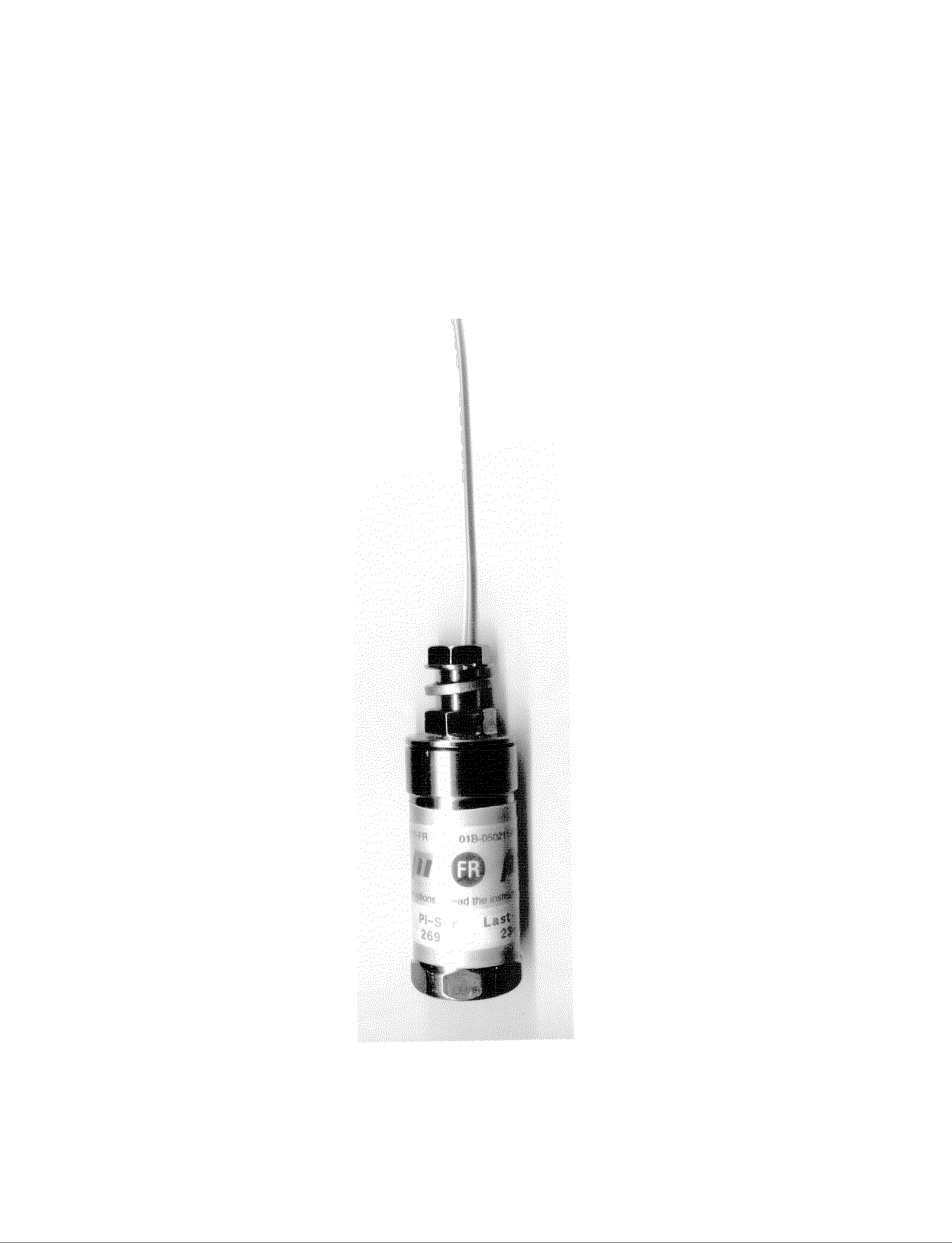
Click to zoom
Application Details
- Equipment Class
- DXX - Part 15 Low Power Communication Device Transmitter
- Date of Grant
- Sep 15, 1999
- Application Purpose
- Original Equipment
- Date of Application
- Jun 23, 1999
- Equipment Note
- Rim Mount Transmitter for the SmarTire Signal Pass
- Frequency Range
- 355.00000000 - 355.00000000
- Country
- Canada
Documents & Files
Document Text
Text extracted from the exhibit documents filed with the FCC. Open a document above to read the original.
Attestation Statements
June 24, 1999 Federal Communications Commission Authorization and Standards Division 7435 Oakland Mills Rd. Columbia, MD 21046 Re: FCC ID: NATTX355MS Gentlemen: Spectrum Technology, Incorporated has tested this Intentional Radiator in accordance with the requirements contained in the Part 15 of Title 47 CFR. To the best of my knowledge, these tests were performed using the criteria established in ANSI C63.4, 1992 and demonstrates that the equipment complies with the published standard. We are unable to warrant against unpublished changes in requirements. The applicable rule sections are listed in the following test report. The Open Area Test Site used for these measurements is located at Fluke Park II, Everett, Washington. Site information required by Public Notice 24541 in accordance with ANSI C63.4- 1992 was filed with the FCC Authorization and Evaluation Division Sampling and Measurements Branch in July 1994 and renewed in January 1998. Sincerely, Rod Munro President Spectrum Technology, Inc. RM/mm
Test Report
APPLICATION FOR CERTIFICATION INTENTIONAL RADIATOR UNDER 47 CFR, PART 15.231(e) SMARTIRE SYSTEMS, INC. FCC ID: NATTX355MS JUNE 24, 1999 Prepared By: Spectrum Technology, Inc. 209 Dayton Street Edmonds, WA 98020 CERTIFICATION TABLE OF CONTENTS Field Strength of Radiated Emissions Setup and Discussion 1 - 2 Tabular Field Strength Results under Part 15.2313 - 4 Antenna Factors and Sample Calculations 5 - 8 Test Equipment List9 Detailed Drawing of Typical RF Data Transmission StreamPDF file attached TEST: FIELD STRENGTH OF RADIATED EMISSIONS Grantee:Smartire Systems, Inc. FCC ID: NATTX355MS Setup: The equipment under test (EUT) was configured and operated in accordance with the applicable provisions of ANSI C63.4-1992, Section 6, 13. Measurements were made in accordance with applicable paragraphs of Section 8.2.3, 8.2.4, Section 13.1.1, 13.1.4 Appendix D, and I. The EUT was placed on a 1 by 1.5 meter table located 40 cm above a 2 meter diameter non-metallic turntable that sits 40 cm above the 15 X 30-meter ground plane at Spectrum's Open Area Test Site. The bi-conical or log-periodic antenna was mounted on a tower spaced at a three meters distance, and arranged for adjustment in height (1-4 meters) and vertical/horizontal polarization to maximize the emissions levels when combined with turntable rotation of the EUT. The dual ridged guide antenna was mounted on a tripod at one-meter height and adjusted for vertical or horizontal antenna orientation. An HP 8562A spectrum analyzer with an HP 8447F, Option H64 amplifier and an HP 83006A pre- amplifier were used for the measuring instrumentation. Discussion: No modifications were required prior to the final radiated emissions measurements reported herein. The EUT is the transmitter for the Smartire Passenger Car Monitoring System that actually uses four 355 MHz transmitters and pressure sensors. A 355 MHz receiver used in the SmartTire Passenger Car Tire Monitoring system would be installed in a passenger vehicle and used to receive signals and display status of passenger tire pressure sensors installed on the wheels. The transmitter and sensor would be installed on the rim of each of the four wheels. Each transmitter reports back to the receiver approximately every eighteen seconds with pressure status and once every minute and a half with temperature status while the vehicle is in motion at speeds in excess of ten miles per hour. If a change in excess of 1 lb is detected the 18 second interval is interrupted. The information is transmitted immediately, being considered a safety issue, as in the case of a punctured tire and treated accordingly. The EUT would normally be installed on a standard steel wheel rim with a typical steel belted radial passenger tire mounted. For the test, the transmitter was set on the table with the antenna standing vertically. The EUT was carefully centered on the table to maintain a 3-meter distance during rotation. The radiated test was conducted this way based on correspondence received for a previous model requiring testing off the rim. Page 1 The transmitter was jumpered to allow continuous repetitive transmission at its maximum date rate. This made it much more convenient to observe maximum emission levels when the turntable was rotated and antenna height and polarization adjusted. Measurements were made for the single frequency AM pulse modulated intentional radiator operating at its nominal operating frequency 355 MHz . Preliminary measurements were made as described in Section 8.3.11 and 13.1.4.1 with the EUT operating as described. The final set of measurements as specified in Section 8.3.1.2 and 13.1.4.2 were made as specified in Section 13.1.1. The transmitter was observed stand alone while positioned on the turntable three meters from the receive antenna. We rotated the turntable and varied antenna height and polarization endeavoring to maximize the signal being measured. The EUT was powered with a fresh battery during all the measurements. RBW and VBW of 100 kHz were used for measurements below 1 GHz. Above 1 GHz peak measurements were made with a RBW and VBW of 1 MHz. The second harmonic was the only harmonic measurable at 3 meters during the final detailed radiated emissions measurements. An HP pre-amplifier was required. A band pass filter was used to attenuated the 355 MHz signal to insure no overloading of the front end of the spectrum analyzer would occur when looking for the low level harmonics. No transmitter antenna conducted emissions measurements were made as we were unable to directly connect the spectrum analyzer to the EUT to recorded the emissions because of the EUT antenna type. Conclusion: The Smartire Systems, Inc., FCC ID: NATTX355MS, when operated and measured as discussed above, meets the field strength of fundamental and spurious emissions requirements under Title 47, CFR Part 15.232(e). This device has shown compliance with the current rules and is not subject to the transition provisions of Part 15.37. Page 2 SPECTRUM TECHNOLOGY, INC. Field Strength of Radiated Fundamental and Spurious Emissions 47 CFR Part 15.231 - Final Data - Ref. _SMARTIR .R2 Grantee:SmarTire Systems, Inc. 03/17/99 FCC ID: NATTX355MS __________________________________________________________________________ Freq Vert Horz Ant-F Amp dBuV/m uV/m Limit Gain peakuV/m MHz dBuV dBuV dB Det. Avg. Det ______________________________________________________________________________ Fo 355 70.50 62.5 18.3 0 88.80 27542.28 3083.34 2Fo 710 36.0 25.0 26.9 0 62.90 1396.37 500 In accordance with Section 15.35(c) when the radiated emissions limits are expressed in terms of the average value of the emission [as in Section 15.231(b)(2)], and pulsed operation is employed, the field strength shall be determined by averaging over one complete pulse train, including blanking intervals, as long as the pulse train does not exceed 0.1 seconds. As an alternative where the pulse train exceeds 0.1 seconds , the measured field strength shal…
Text truncated - open the document above for the full version.
Contact Information
Applicant
Robert Patterson(RF Engineer)
Technical Contact
Spectrum Technology IncRod Munro
[email protected]425 771-4482
209 Dayton Street · Edmonds, Washington · United States
Non-Technical Contact
Spectrum Technology IncRod Munro
[email protected]425 771-4482
Test Firm
Spectrum Technology Inc.Rod Munro
Technical Specifications
| # | Rule Parts | Frequency Range | Power Output |
|---|---|---|---|
| 1 | 15C | 355 MHz - 355 MHz | - |
Other Applications from Bendix Commercial Vehicle Systems LLC
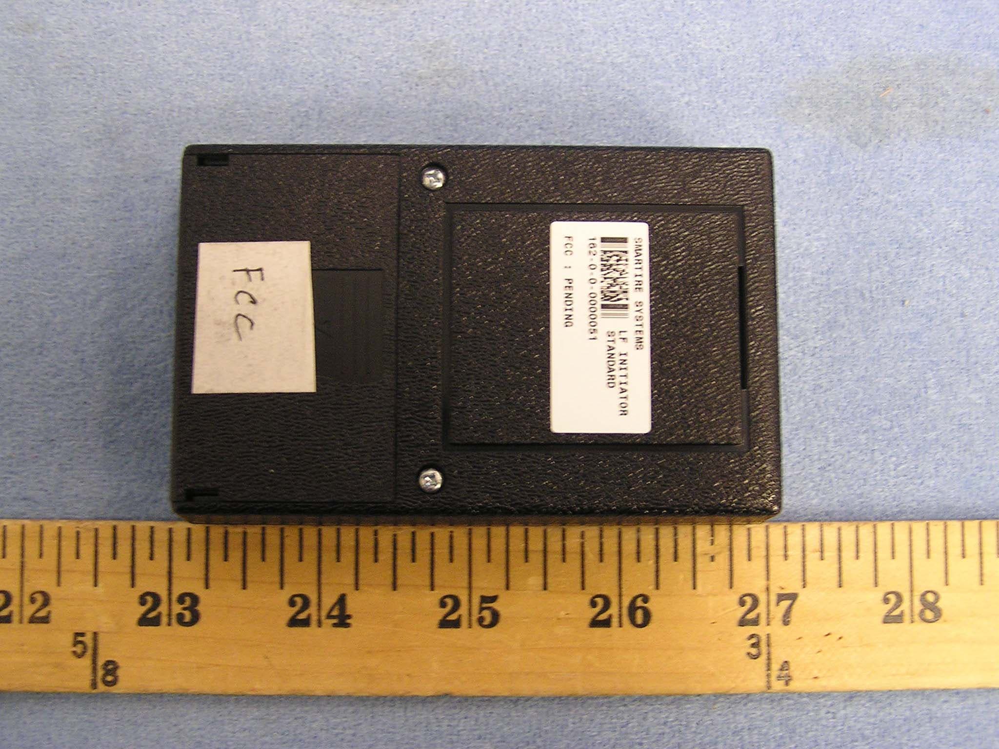
NATLF0162
Jan 06, 2005LF Initiation Tool, 125 kHz LF Transmitter
Equipment Class
DCD - Part 15 Low Power Transmitter Below 1705 kHz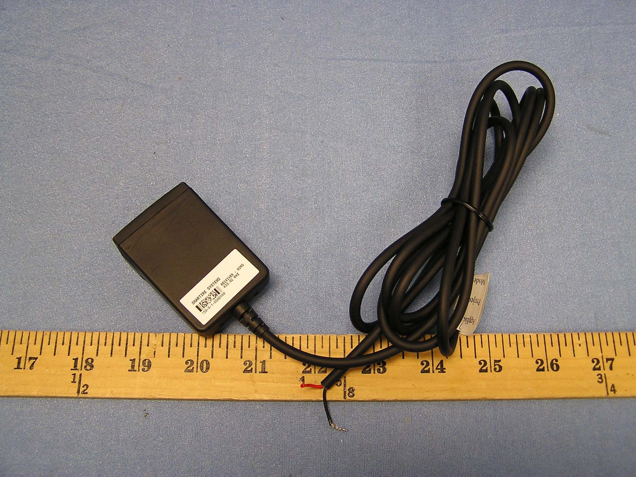
NATMIRD433
Jun 07, 2004433.92MHz Receiver
Equipment Class
CYY - Communications Receiver used w/Pt 15 Transmitter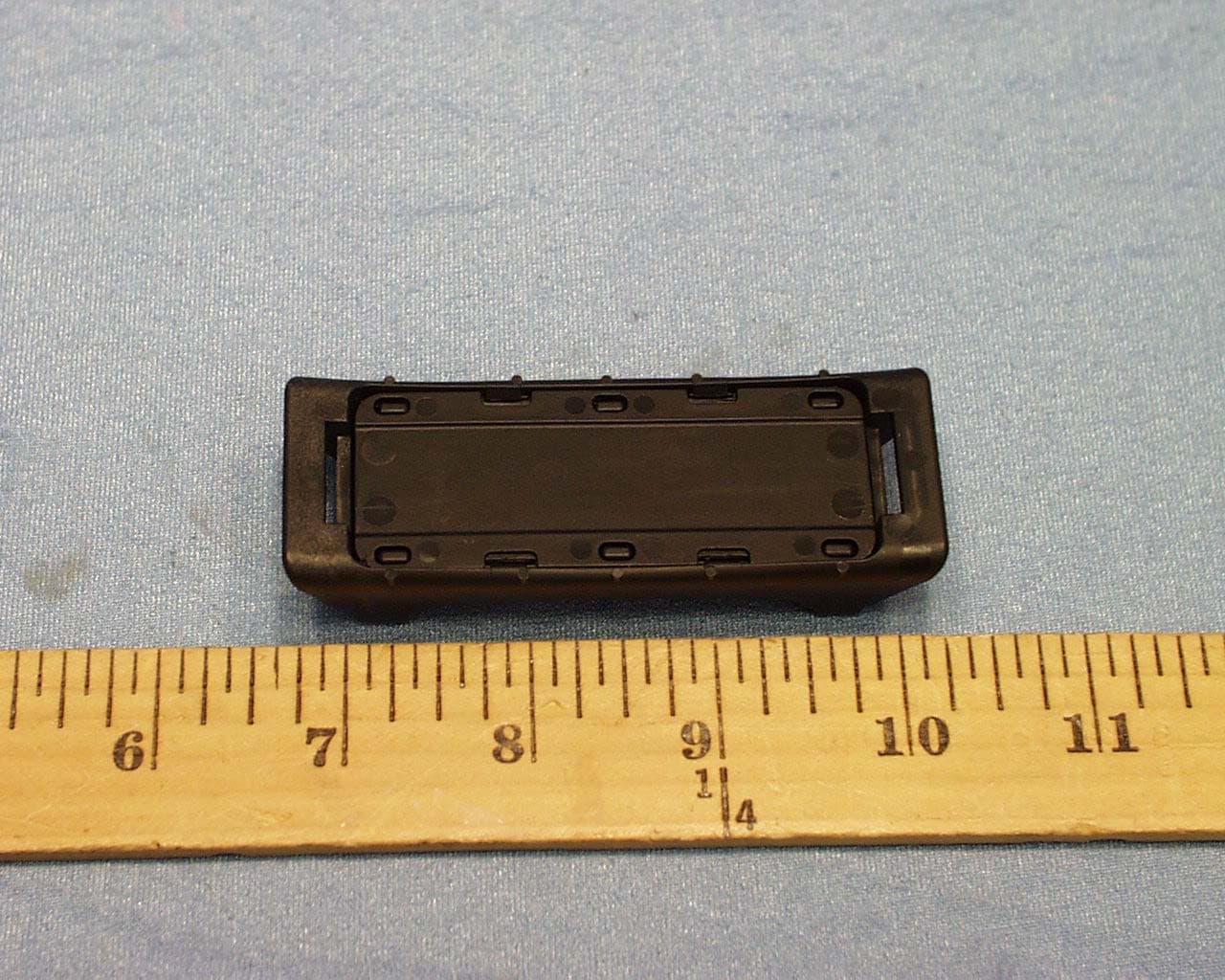
NATTX433CS-3
Jun 03, 2004Tire Monitoring Sensor
Equipment Class
DSC - Part 15 Security/Remote Control Transmitter
NATRX433-RV-1
Apr 09, 2003Tire Monitoring System-Display Receiver
Equipment Class
CYY - Communications Receiver used w/Pt 15 Transmitter
NATTX433CS-2
Apr 08, 2003Tire Monitoring Sensor
Equipment Class
DSR - Part 15 Remote Control/Security Device Transceiver