NATTX433TS-2Wireless Tire Monitoring System
Bendix Commercial Vehicle Systems LLCApplication Details
- Equipment Class
- DSC - Part 15 Security/Remote Control Transmitter
- Date of Grant
- Jul 16, 2001
- Application Purpose
- Original Equipment
- Date of Application
- Feb 15, 2001
- Equipment Note
- Wireless Tire Monitoring System
- Frequency Range
- 433.92000000 - 433.92000000
- Country
- Canada
Documents & Files
Document Text
Text extracted from the exhibit documents filed with the FCC. Open a document above to read the original.
Users Manual
SmarTire Systems Inc. Tire Monitoring System Reference Manual 6/13/2000 Page 1 of 55 This manual is under review by SmarTire – DO NOT ISSUE Draft Tire Monitor System Reference Manual GENII Draft Note; Prior to issue this manual to be examined and approved by; Engineering Marketing Customer Service SmarTire Systems Inc. Tire Monitoring System Reference Manual 6/13/2000 Page 2 of 55 This manual is under review by SmarTire – DO NOT ISSUE Table of Contents FCC Notice.....................................................................................................................5 Introduction....................................................................................................................6 Purpose of Manual................................................................................................................6 About Tire Monitoring Systems...........................................................................................6 Feature Summary..........................................................................................................................................7 System Scope of Use and Warnings......................................................................................8 The SmarTire™ System and Tire Maintenance..............................................................................................8 System Installation and Usage.......................................................................................................................8 Use of Chemicals..........................................................................................................................................8 Power Connection.........................................................................................................................................8 Warnings......................................................................................................................................................8 SmarTire Product Overview........................................................................................10 Product List.........................................................................................................................10 Tire Monitor System Kit Component Table......................................................................11 System Descriptions............................................................................................................12 Pressure Alert Systems – 2 and 4 wheels – Multi-fit Strap Mount Transmitters.............................................12 Overview................................................................................................................................................12 Bill of Materials.....................................................................................................................................13 Component Images.................................................................................................................................14 Pressure Alert Systems – 2 and 4 wheels – Multi-fit Valve Mount Transmitters............................................15 Overview................................................................................................................................................15 Bill of Materials.....................................................................................................................................16 Component Images.................................................................................................................................17 Pressure Alert Full Function Display...........................................................................................................18 Overview................................................................................................................................................18 Bill of Materials.....................................................................................................................................19 Component Images.................................................................................................................................19 Pressure Alert Flexible Power Adaptor........................................................................................................20 Overview................................................................................................................................................20 Bill of Materials.....................................................................................................................................20 Component Image..................................................................................................................................20 Pressure Alert Transmitter Kit – 2 - Multi-fit Strap Mount Transmitters.......................................................21 Overview................................................................................................................................................21 Bill of Materials.....................................................................................................................................21 Component Image..................................................................................................................................21 Pressure Alert Transmitter Kit – 2 - Multi-fit Valve Mount Transmitters......................................................22 Overview................................................................................................................................................22 Bill of Materials.....................................................................................................................................22 Component Image...........................................................................................................…
Text truncated - open the document above for the full version.
Attestation Statements
Project: Commercial Project Confidential Record ID:Date: Author: Mitra SalimiPage 1 of 1 January 25, 2001 Federal Communications Commission Authorization and Evaluation Division 7435 Oakland Mills Rd. Columbia, MD 21046 Re: FCC ID’s : NATTX433TS-2, NATTX433TV-1 Applicant: SmarTire Systems, Inc. Gentlemen: Under the provisions of CFR 47, Part 0.459 requests that Exhibits listed below, for the above referenced Certification application, are with held from public viewing. The reason for withholding the information under Part 0.457 (d) is cited as trade secrets. Smartire considers this information proprietary in nature and asks that the Exhibits be treated in a confidential manner and not made available to the general public. Release of such information could result in serious financial harm and the loss of company proprietary information. Exhibit IVBlock Diagrams Theory of Operation Exhibit VSchematics Diagrams Exhibit XBOM If you have any questions concerning this request please feel free to call Robert Patterson at 604 276- 9884 or Rod Munro 425 771-4482. Regards, Mr Robert Patterson, RF Design En g.
Cover Letter(s)
Attn.: Katie Hawkins [email protected] FCC Application Processing Branch Re: FCC ID NATTX433TS-2 Applicant: SmarTire Systems Inc Correspondence Reference Number: 18481 731 Confirmation Number: EA100081 Dear Katie, The following answers are submitted in response to your two questions. 1). When there is a reduction in pressure, at what rate will the sensor transmit? When there is a reduction in pressure the sensor transmits once every 15 seconds for 4 times. If the pressure reduction stops then it transmits every 4 minutes. If the pressure keeps reducing it keeps transmitting every 15 seconds. 2). Submit time domain plots from which the duty cycle correction factor may be calculated. The time domain plot is on the page following. If you would like greater detail I can submit the TRW datagrams that contain eight pages of details for the components used. The sensor transmits 10 packets of data with each packet length 18.5 ms within 500 ms. every 4 – 6 minutes. So typically 2 packets in 100 ms period with a total packet length of 37 ms in 100 ms. With the BiPhase 50% on off duty cycle the EUT total on time in 100 ms then is 18.5 %. (18.5 ms + 18.5 ms = 37 ms total packet length at a 50% duty cycle = 18.5% / 100 ms). Note the marker shows 19 ms which is within the range of instrument error with a 100 ms sweep. Best Regards, Rod Munro
Cover Letter(s)
Project: Confidential Record ID: Date: Author: Robert Patterson Page 1 of 1 Attn: Kaite Hawkins Federal Communications Commission, Applications Processing Branch, 7435 Oakland Mills Road, Columbia, MD 21046. RE: SmarTire Systems Inc #150 13151 Vanier Place Richmond, BC V6V2J1 (604) 276-9884 Dear Katie In response to the telephone conference and subsequent emails regarding FCC issues of our devices (NATTX433TS-2 (433 MHZ Strap mount transmitter) and NATTX433TV-1 (433 MHZ Valve mount transmitter)) the following changes where done to both products to comply with FCC regulations. (1) Since both products did not comply with FCC regulations due to the added 12 ms low power pulse, it was decided to reduce the power of this 12 ms pulse to 0. This change was done by changing the value of one resistor in the circuit from a 4k7 to a 15k. (2) Since the data pulse is BiPhase, the length of each packet is 18.5 ms and there are 2 packets in 100ms, then the duty cycle would be 18.5%. (3) The devices were then retested by Spectrum Technologies to prove that the power of the 12 ms pulse is off. If any further questions arise please contact either Rod Munro at Spectrum Technologies or Robert Patterson at SmarTire Systems Inc. Thank You Sincerely Robert Patterson RF Design Eng SmarTire Systems Inc #150 13151 Vanier Place Richmond, BC (604) 276-9884
ID Label/Location Info
Applicant: SmarTire Systems Inc. FCC ID: NATTX433TS-2 Exhibit 1 LIST OF EXHIBITS DESCRIPTION EXHIBITSREFERENCE I.Identification label Information12.1033 (b) 7 & 2.925 & General Information1A 1. Production Plans2.1031 2. Application ReferencesN/A 3. Data submittal Procedure 4. Similar Certified Transmitter II.Certification Data2 III.External Photographs 32.1033 (b) 7 IV.Theory of Operation & Block Diagrams 42.1033 (b) 5 V. Schematic Diagrams & Antenna Assembly 52.1033 (b) 5 VI.Test Report 6 2.1033 (b) 6 6 15.247 (a, b, c, g, h) VII.Test Set-up Procedures7 2.1041 VIII.Instruction Manual82.1033 (b) 3 IX.Internal Photographs92.1033 (b) 7 X.Part List / BOM 10N/A XI.RF Exposure Information11 2.1093 XII.Operational Description122.1033 (b) 1, 2, 4, 8 Antenna Requirements1215.203 1. Technical Characteristics 1 - 5 2. Application XIII. Cover Letter, Action Requested13 Cover Letter, Agent Authorization To Sign Form 73113 Applicant: SmarTire Systems Inc. FCC ID: NATTX433TS-2 Exhibit 1 EXHIBIT 1. FCC IDENTIFICATION LABEL 47 CFR 2.1033(C) 11 LOCATION Top side of the transmitter sensor housing. Sample FCC ID Labels are on the next page. Exhibit 1A. General Information 1A.1. Production Plans -- Pursuant 47 CFR 2.1031 Quantity production is planned. 1A.2.Application References -- Pursuant 47 CFR 2.1061 N/A for use Under Part 15 not licensed systems 1. Part 15 Security and Remote Control transmitter 1A.3.Data Submittal Procedure Data located in Exhibit 6 is supplied in accordance with Part 2, Sub-part J and Part 15, Sub-part C of the Commissions’ rules and will be submitted electronically. 1A.4.Similar, Currently Certified Intentional Radiator The FCC ID: NATTX433VM, a similar transmitter, is also manufactured by SmarTire Systems, Inc. and used for the same tire pressure and temperature sensor application. THISINFORMATIONISPROPRIETARYANDMUSTNOT BECOPIEDAND/ORREVEALEDTOTHIRDPARTIES WITHOUTTHEWRITTENCONSENTOFSMARTIRESYSTEMSINC. Title Drawn C.Libera Checked Labelspecification,FCC-transmitterTS-2 DWGNO.269.0117.19-22.AD(DL-1286) REVREL DescriptionDATE INIT Designer C.Libera Manager S.Lammers 3-Jan-01 CLOriginal 00 Proto PilotProduction() 2001 SmarTireSystemsInc. #150-13151VanierPlace,Richmond,BritishColumbiaV6V2J1 269.0117.19 269.0117.20 269.0117.21 269.0117.22 100-1234567 SmarTireSystems Page1of1 FCCID:NATTX433TS-2 P4 FCCID:NATTX433TS-2 P3 FCCID:NATTX433TS-2 P2 FCCID:NATTX433TS-2 P1 FCCID:NATTX433TS-2 P1 FCCLabelIDSNLabel LabelProductionProcedure 1.Usecolorcodedlabelstock269.0117.02to.05 respectively. 2.PrintFCCnumber,barcodeand position(P1-P4)asshown.
Operational Description
Applicant: SmarTire Systems Inc.FCC ID: NATTX433TS-2 Exhibit 12 XII. Operational Description Information required by Section 2.1033(b) 1 - 12 1. The Applicant and Manufacturer of is: SmarTire Systems, Inc. #150 – 13151 Vanier Place Richmond, BC V6V 2J1 Canada 2. New FCC ID: NATTX433TS-2 3. Please refer to Exhibit VIII Instruction Manual 4. Please refer to Exhibit 12 for a description of the Intentional Radiator circuitry and function. The details concerning the antenna are uploaded with Exhibit 5. 5. Exhibit 4 is a block diagram of the device. Information required by Section 2.1033(b) 1 – 12, continued. 6. Exhibit 6 is the radiated emissions test report. 7. Exhibits III and IX are external and internal photographs of device. 8. Data Cables Available: Does Not Apply 9. This equipment is not subject to the transition provisions of Part 15.37. 10. Does Not Apply 11. Does Not Apply 12. Does Not Apply Applicant: SmarTire Systems Inc.FCC ID: NATTX433TS-2 Exhibit 12 Additional Technical Information 1. Technical Characteristics 1a.) Technical description: 433 MHz AM pulsed transmitter 1b.) Transmitter Application: The transmitter in installed within a tire on the rim and used for temperature and pressure sensing and wireless communications to a receiver in the vehicle. 1c.) Power Supply Available: Panasonic Battery – BR1632A-L 3V, 1d.) Antenna available: Part Number: 2.00093. The helical antenna is integrated within the sensor 1e.) Data Cables Available: Not applicable 1f.) Housing: The transmitter PCB and antenna are integrated within the sensor housing. The antenna is mounted directly to the transmitter PCB.
Test Report
EXHIBIT 6 TEST REPORT For CERTIFICATION INTENTIONAL RADIATOR Under 47 CFR, Part 15.231(e) SmarTire Systems, Inc. FCC ID: NATTX433TS-2 February 16, 2001 Prepared By: Spectrum Technology, Inc. 209 Dayton Street Edmonds, WA 98020 425 771- 4482 CERTIFICATION TABLE OF CONTENTS Field Strength of Radiated Emissions Setup and Discussion 1 - 2 Tabular Field Strength Results under Part 15.231(e)3 - 4 Occupied Bandwidth Profile of the Transmitter5 - 6 TEST: FIELD STRENGTH OF RADIATED EMISSIONS Grantee:SmarTire Systems, Inc. FCC ID: NATTX433TS-2 Setup: The equipment under test (EUT) was configured and operated in accordance with the applicable provisions of ANSI C63.4-1992, Section 6, 13. Measurements were made in accordance with applicable paragraphs of Section 8.2.3, 8.2.4, Section 13.1.1, 13.1.4 Appendix D, and I. The EUT was placed on a 1 by 1.5 meter table located 40 cm above a 2 meter diameter non- metallic turntable that sits 40 cm above the 15 X 30-meter ground plane at Spectrum's Open Area Test Site. The bi-conical or log-periodic antenna was mounted on a tower spaced at a three meters distance, and arranged for adjustment in height (1-4 meters) and vertical/horizontal polarization to maximize the emissions levels when combined with turntable rotation of the EUT. The dual ridged guide antenna was mounted on a tripod at one-meter height and adjusted for vertical or horizontal antenna orientation. An HP 8562A spectrum analyzer with an HP 8447F, Option H64 amplifier and an HP 83006A pre-amplifier were used for the measuring instrumentation. Discussion: No modifications were made during the final radiated measurements reported herein. The EUT is the transmitter for the Smartire Pressure and Temperature Monitoring System which uses four 433.92 MHz transmitter/sensors. A 433 MHz receiver and display module used in the SmartTire Monitoring System, FCC ID: NATBR433BP, would be installed in a passenger vehicle and used to receive signals and display status of tire pressure and temperature sensors. The transmitter/sensor is installed within each tire with a stainless steel strap on to the rim of each wheel. Each transmitter reports back to the receiver approximately every four to six minutes continuously with pressure and temperature status transmitted in 10 18.5 ms packets within 500 ms. If a reduction in pressure is sensed the sensor will transmit more frequently. The information being considered a safety issue, as in the case of a punctured tire and an alarm is displayed on the receiver. For the radiated emissions test, the transmitter was set on the table and tested while positioned in three orthogonal planes. The position of the sensor was observed to make little difference and final testing was done with the position depicted in the photo of the test setup uploaded with this report. The EUT was carefully centered on the table to maintain a 3-meter distance during rotation. The radiated test setup was conducted this way based on previous correspondence from the lab requiring testing the EUT off the rim for earlier models. Page 1 The transmitter was jumpered with two leads brought out externally specifically to allow continuous packet transmission at its maximum date rate. This made it practical to observe maximum emission levels when the turntable was rotated and antenna height and polarization adjusted. Measurements were made for the single frequency 433.92 MHz AM pulse modulated intentional radiator operating at its nominal operating frequency with a data rate of 3kHz in a BiPhase format . Preliminary measurements were made as described in Section 8.3.11 and 13.1.4.1 with the EUT operating as described. The final set of measurements as specified in Section 8.3.1.2 and 13.1.4.2 were made as specified in Section 13.1.1. The transmitter was observed stand alone while positioned on the turntable three meters from the receive antenna. We rotated the turntable and varied antenna height and polarization endeavoring to maximize the signal being measured. The EUT was powered with a new battery during the measurements. RBW and VBW of 100 kHz were used for measurements below 1 GHz. Above 1 GHz peak measurements were made with a RBW and VBW of 1 MHz. Most of the harmonics through 10 Fo were measurable at 3 meters during the final detailed radiated emissions measurements. An HP pre-amplifier was used along with a band pass filter to attenuated the 433.92 MHz signal and avoid any question of overloading the front end of the spectrum analyzer. Conclusion: The SmarTire Systems, Inc., FCC ID: NATTX433TS-2, when operated and measured as discussed above, complies with the field strength of the fundamental limit and limits for spurious emissions requirements under Title 47, CFR Part 15.231(e). Duty cycle averaging was applied to the peak reading to comply with the 4399uV/m average detector limit. This device has shown compliance with the current rules and is not subject to the transition provisions of Part 15.37. Page 2 SPECTRUM TECHNOLOGY, INC. Field Strength of the Fundamental and Spurious Radiated Emissions 47 CFR Part 15.231 - Final Data - Ref. SMARTIR .TS-2 Grantee:SmarTire Systems, Inc. 01/19/01 FCC ID: NATTX433TS-2 _________________________________________________________________________________ Freq Vert HorzAnt-FCable AmpCorrecteduV/m Limit uV/m inRdg. Rdg.& BPFGainRdg in PeakAverage MHz dBuV dBuV Loss dB dBuV/m detectordetector __________________________________________________________________________________________ Fo 433.9258.50 60.8322.60 3.3 086.73 21702 4399 2Fo 867.84 24.67 28.3327.70 6.5 inc.62.53 1338 500 3Fo1.3017622.33 30.5025.70 1.0527.0030.25 32 “ ” 4Fo1.7356825.67 34.5027.15 1.22 25.3037.57 75 “ ” 5Fo2.1696018.83 27.1727.15 1.2224.0031.54 37 “ ” 6Fo2.60325 *14.0 *15.00 28.37 1.3822.1022.65 13 “ ” 7Fo3.03744*14.83 *12.0029.93 1.53 21.3024.99 18 “ ” 8Fo3.47136021.17 21.6731.01 1.6721.2033.15 45 “ ” 9Fo3.90528018.83 17.8334.45 1.8021.6033.48 47 “ ” 10Fo4.33920029.33 23.8331.98 1.9222.541.5410…
Text truncated - open the document above for the full version.
Test Report
SPECTRUM TECHNOLOGY, INC. Field Strength of the Fundamental and Spurious Radiated Emissions 47 CFR Part 15.231 - Final Data - Ref. SMARTIR4 .TS-2 Grantee:SmarTire Systems, Inc. 07/02/01 FCC ID: NATTX433TS-2 _________________________________________________________________________________ Freq Vert Horz Ant-F Cable Amp Corrected uV/m Limit uV/m in Rdg. Rdg. & BPF Gain Rdg in PeakAverage MHz dBuV dBuV Loss dB dBuV/m detectordetector __________________________________________________________________________________________ Fo 433.92 56.00 61.67 21.60 2.4 0 84.00 15848 2932 2Fo 867.84 50.00 54.00 27.70 6.5 25.00 63.2 1445 500 3Fo 1.30176 58.17 66.50 25.70 1.05 27.00 66.25 2053 “ ” 4Fo 1.73568 53.17 63.83 27.15 1.22 25.30 66.9 2213 “ ” 5Fo 2.16960 46.00 50.17 27.15 1.22 24.00 54.54 533 “ ” 6Fo 2.60325 34.67 41.83 28.37 1.38 22.10 49.48 297 “ ” 7Fo 3.03744 32.83 37.67 29.93 1.53 21.30 47.83 246 “ ” 8Fo 3.471360 47.33 36.17 31.01 1.67 21.20 58.81 871 “ ” 9Fo 3.905280 39.33 48.83 34.45 1.80 21.60 63.48 1493 “ ” 10Fo 4.339200 40.67 42.50 31.98 1.92 22.5 53.90 495 “ ” Note: The highest level in dBuV of the Vertical or Horizontal Reading is calculated above. Limit for the band 260 - 470 MHz, uV/m at 3 meters = 16.6667(F) - 2833.3333. Limit at 433.92 MHz = 4399 uV/m average detector limit, Section 15.231(e). Peak detector field strength was measured at 21702 uV/m at 3 meters. With the 18.5% duty cycle = 2932 uV/m calculated average detector field strength with an average detector limit of 4399uV/m. Page 3 Averaging Correction Applied In accordance with Section 15.35(c) when the radiated emissions limits are expressed in terms of the average value of the emission [as in Section 15.231(b)(2)], and pulsed operation is employed, the field strength shall be determined by averaging over one complete pulse train, including blanking intervals, as long as the pulse train does not exceed 0.1 seconds. As an alternative where the pulse train exceeds 0.1 seconds , the measured field strength shall be determined from the average absolute voltage during a 0.1-second interval during which its field strength is at its maximum value ANSI C63.4-1992 Appendix I4 (10) also describes a method which we used to correct for duty cycle when average detector function limits are specified for a pulse-modulated transmitter, the average level of emissions may be found by measuring the peak level of emissions and correcting them with duty cycle. When the pulse train exceeds 100 ms calculate the duty cycle by averaging the sum of the pulse widths with the highest average over the 100 ms width with the highest average value. The duty cycle is the value of the sum of the pulse widths in one period (or 100 ms) divided by the length of the period (or 100 ms). We multiplied the peak detector field strength in uV/m of the emission from the transmitter by the duty cycle calculated to determine the average detector field strength of the emission for comparison to the average detector limit in Part 15.231. The sensor transmits 10 packets of data with each packet length 18.5 ms within 500 ms. every 4 – 6 minutes. So typically 2 packets in 100 ms period with a total packet length of 37 ms in 100 ms. With the transmission BiPhase with a 50% on off duty cycle the EUT total on time in 100 ms then is 18.5 %. (18.5 ms + 18.5 ms = 37 ms total packet length at a 50% duty cycle = 18.5% / 100 ms) Note: Two plots of the transmitter occupied bandwidth for your reference follow on the next two pages showing the time domain characteristics at 50 and 100 ms sweep settings. Page 4
Test Report
SPECTRUM TECHNOLOGY, INC. Field Strength of the Fundamental and Spurious Radiated Emissions 47 CFR Part 15.231 - Final Data - Ref. SMARTIR4 .TS-2 Grantee:SmarTire Systems, Inc. 07/13/01 FCC ID: NATTX433TS-2 _________________________________________________________________________________ Freq Vert Horz Ant-F Cable Amp Corrected uV/m Limit uV/m in Rdg. Rdg. & BPF Gain Rdg in Peak Average MHz dBuV dBuV Loss dB dBuV/m detectordetector ________________________________________________________________________________________ __ Fo 433.92 56.00 61.67 21.60 2.4 0 85.17 19208 4339 2Fo 867.84 50.00 54.00 27.70 6.5 25.00 63.2 1445 500 3Fo 1.30176 58.17 66.50 25.70 1.05 27.00 66.25 2053 “ ” 4Fo 1.73568 53.17 63.83 27.15 1.22 25.30 66.9 2213 “ ” 5Fo 2.16960 46.00 50.17 27.15 1.22 24.00 54.54 533 “ ” 6Fo 2.60325 34.67 41.83 28.37 1.38 22.10 49.48 297 “ ” 7Fo 3.03744 32.83 37.67 29.93 1.53 21.30 47.83 246 “ ” 8Fo 3.471360 47.33 36.17 31.01 1.67 21.20 58.81 871 “ ” 9Fo 3.905280 39.33 48.83 34.45 1.80 21.60 63.48 1493 “ ” 10Fo 4.339200 40.67 42.50 31.98 1.92 22.5 53.90 495 “ ” Note: The highest level in dBuV of the Vertical or Horizontal Reading is calculated above. Limit for the band 260 - 470 MHz, uV/m at 3 meters = 16.6667(F) - 2833.3333. Limit at 433.92 MHz = 4399 uV/m average detector limit, Section 15.231(e). Peak detector field strength was measured at 19208 uV/m at 3 meters. With the 18.5% duty cycle = 3553 uV/m calculated average detector field strength with an average detector limit of 4399uV/m. Page 3
Test Report
SPECTRUM TECHNOLOGY, INC. Field Strength of the Fundamental and Spurious Radiated Emissions 47 CFR Part 15.231 - Final Data - Ref. SMARTIR4 .TS-2 Grantee:SmarTire Systems, Inc. 07/13/01 FCC ID: NATTX433TS-2 _________________________________________________________________________________ Freq Vert Horz Ant-F Cable Amp Corrected uV/m Limit uV/m in Rdg. Rdg. & BPF Gain Rdg in Peak Average MHz dBuV dBuV Loss dB dBuV/m detectordetector ________________________________________________________________________________________ __ Fo 433.92 56.00 61.67 21.60 2.4 0 85.67 19208 4339 2Fo 867.84 50.00 54.00 27.70 6.5 25.00 63.2 1445 500 3Fo 1.30176 58.17 66.50 25.70 1.05 27.00 66.25 2053 “ ” 4Fo 1.73568 53.17 63.83 27.15 1.22 25.30 66.9 2213 “ ” 5Fo 2.16960 46.00 50.17 27.15 1.22 24.00 54.54 533 “ ” 6Fo 2.60325 34.67 41.83 28.37 1.38 22.10 49.48 297 “ ” 7Fo 3.03744 32.83 37.67 29.93 1.53 21.30 47.83 246 “ ” 8Fo 3.471360 47.33 36.17 31.01 1.67 21.20 58.81 871 “ ” 9Fo 3.905280 39.33 48.83 34.45 1.80 21.60 63.48 1493 “ ” 10Fo 4.339200 40.67 42.50 31.98 1.92 22.5 53.90 495 “ ” Note: The highest level in dBuV of the Vertical or Horizontal Reading is calculated above. Limit for the band 260 - 470 MHz, uV/m at 3 meters = 16.6667(F) - 2833.3333. Limit at 433.92 MHz = 4399 uV/m average detector limit, Section 15.231(e). Peak detector field strength was measured at 19208 uV/m at 3 meters. With the 18.5% duty cycle = 3553 uV/m calculated average detector field strength with an average detector limit of 4399uV/m. Page 3
Contact Information
Applicant
Robert Patterson(RF Engineer)
Technical Contact
Spectrum Technology IncRod Munro
[email protected]425 771-4482
209 Dayton Street · Edmonds, Washington · United States
Non-Technical Contact
Spectrum Technology IncRod Munro
[email protected]425 771-4482
Test Firm
Spectrum Technology Inc.Rod Munro
Technical Specifications
| # | Rule Parts | Frequency Range | Power Output |
|---|---|---|---|
| 1 | 15.231(e) | 433.92 MHz - 433.92 MHz | - |
Other Applications from Bendix Commercial Vehicle Systems LLC
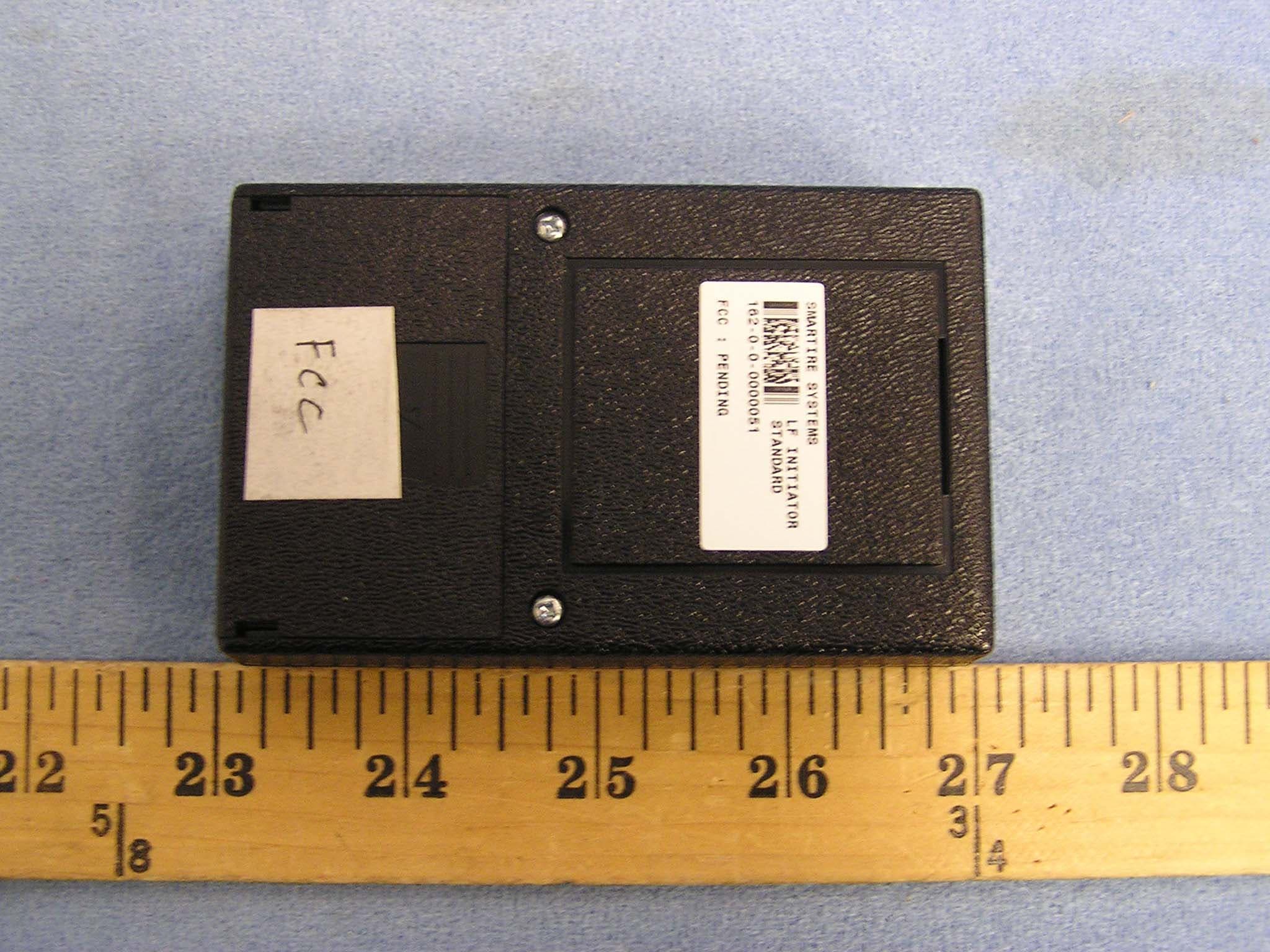
NATLF0162
Jan 06, 2005LF Initiation Tool, 125 kHz LF Transmitter
Equipment Class
DCD - Part 15 Low Power Transmitter Below 1705 kHz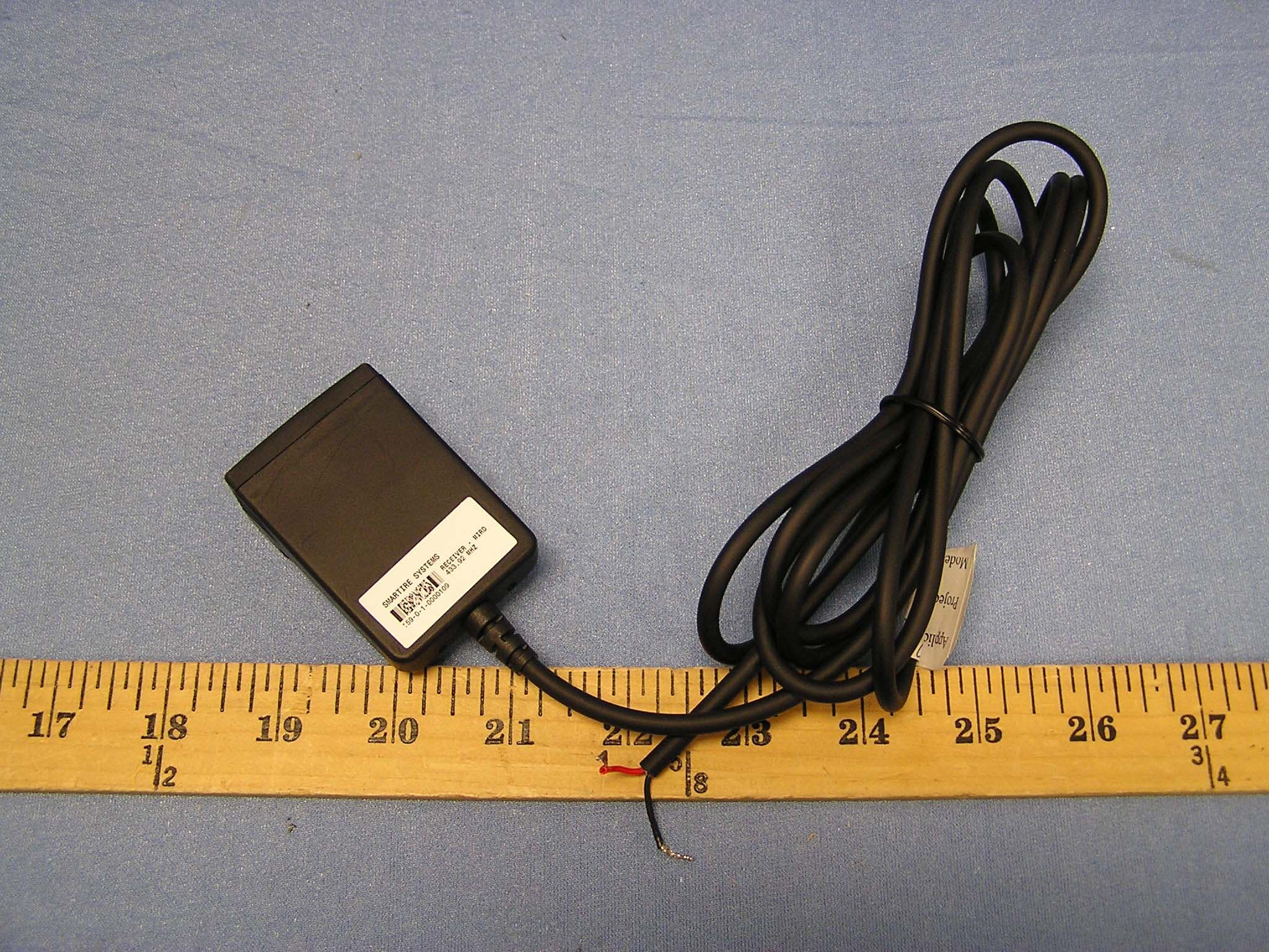
NATMIRD433
Jun 07, 2004433.92MHz Receiver
Equipment Class
CYY - Communications Receiver used w/Pt 15 Transmitter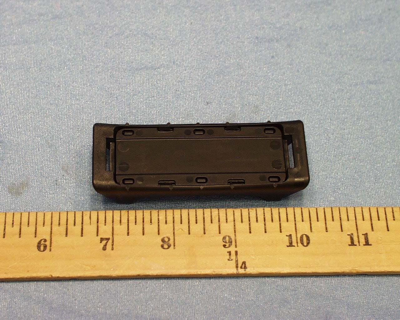
NATTX433CS-3
Jun 03, 2004Tire Monitoring Sensor
Equipment Class
DSC - Part 15 Security/Remote Control Transmitter
NATRX433-RV-1
Apr 09, 2003Tire Monitoring System-Display Receiver
Equipment Class
CYY - Communications Receiver used w/Pt 15 Transmitter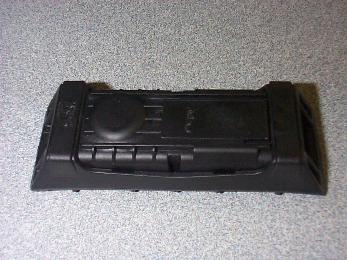
NATTX433CS-2
Apr 08, 2003Tire Monitoring Sensor
Equipment Class
DSR - Part 15 Remote Control/Security Device Transceiver