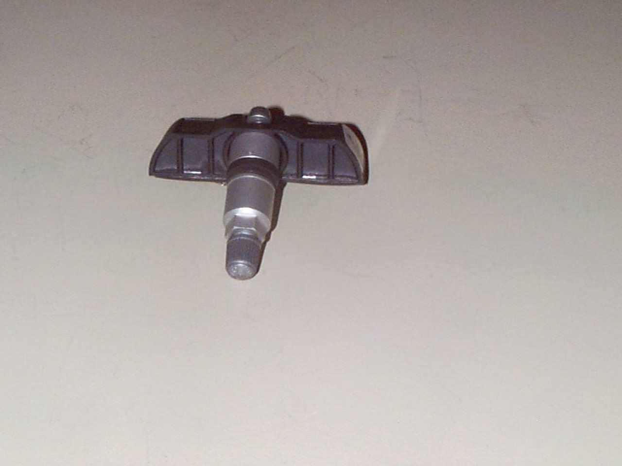
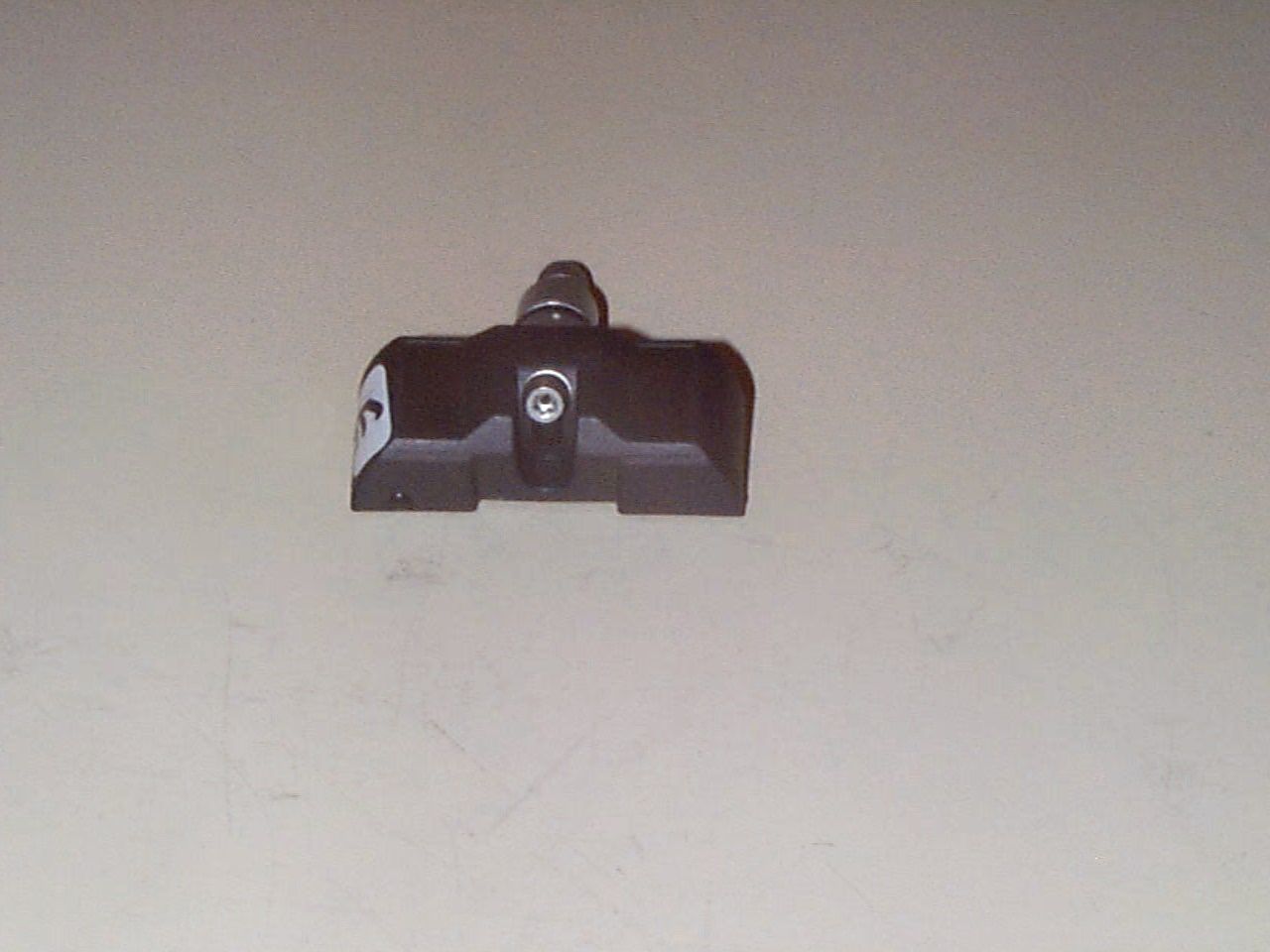
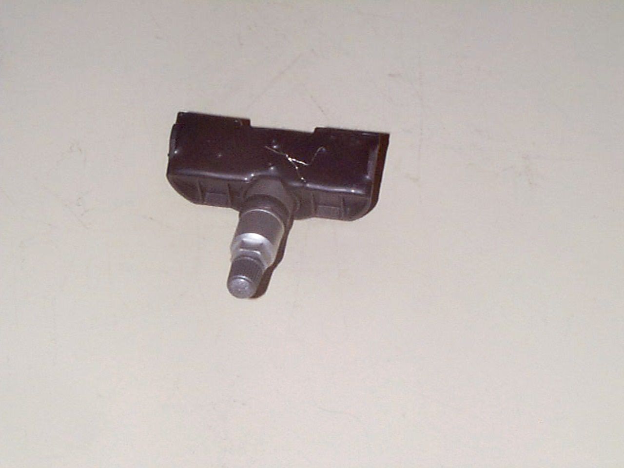
NATTX433VMTire pressure and heat sensor transmitter
Bendix Commercial Vehicle Systems LLC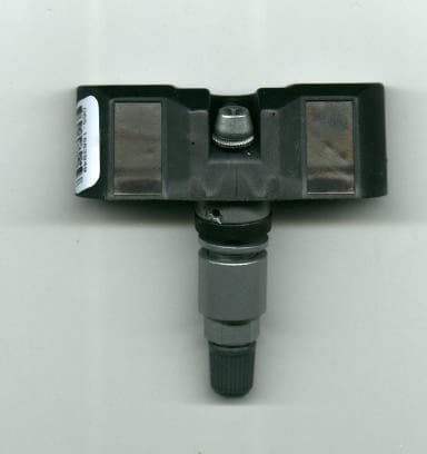
Click to zoom
Application Details
- Equipment Class
- DSC - Part 15 Security/Remote Control Transmitter
- Date of Grant
- Oct 03, 2000
- Application Purpose
- Original Equipment
- Date of Application
- Jun 27, 2000
- Equipment Note
- Tire pressure and heat sensor transmitter
- Frequency Range
- 433.92000000 - 433.92000000
- Country
- Canada
Documents & Files
Document Text
Text extracted from the exhibit documents filed with the FCC. Open a document above to read the original.
Users Manual
SmarTire Systems Inc. Tire Monitoring System Reference Manual 6/20/2000 Page 1 of 56 This manual is under review by SmarTire – DO NOT ISSUE Draft Tire Monitor System Reference Manual GENII Draft Note; Prior to issue this manual to be examined and approved by; Engineering Marketing Customer Service SmarTire Systems Inc. Tire Monitoring System Reference Manual 6/20/2000 Page 2 of 56 This manual is under review by SmarTire – DO NOT ISSUE Table of Contents FCC Notice...................................................................................................................................5 Introduction.................................................................................................................................6 Purpose of Manual....................................................................................................................6 About Tire Monitoring Systems..............................................................................................6 Feature Summary..................................................................................................................................................................7 System Scope of Use and Warnings........................................................................................8 The SmarTire™ System and Tire Maintenance..............................................................................................................8 System Installation and Usage............................................................................................................................................8 Use of Chemicals..................................................................................................................................................................8 Power Connection.................................................................................................................................................................8 Warnings.................................................................................................................................................................................8 SmarTire Product Overview..................................................................................................10 Product List.............................................................................................................................10 Tire Monitor System Kit Component Table........................................................................11 System Descriptions................................................................................................................12 Pressure Alert Systems – 2 and 4 wheels – Multi-fit Strap Mount Transmitters.....................................................12 Overview.........................................................................................................................................................................12 Bill of Materials.............................................................................................................................................................13 Component Images........................................................................................................................................................14 Pressure Alert Systems – 2 and 4 wheels – Multi-fit Valve Mount Transmitters....................................................15 Overview.........................................................................................................................................................................15 Bill of Materials.............................................................................................................................................................16 Component Images........................................................................................................................................................17 Pressure Alert Full Function Display...............................................................................................................................18 Overview.........................................................................................................................................................................18 Bill of Materials.............................................................................................................................................................19 Component Images........................................................................................................................................................19 Pressure Alert Flexible Power Adaptor...........................................................................................................................20 Overview.........................................................................................................................................................................20 Bill of Materials.............................................................................................................................................................20 Component Image..........................................................................................................................................................20 Pressure Alert Transmitter Kit – 2 - Multi-fit Strap Mount Transmitters.................................................................21 Overview.........................................................................................................................................................................21 Bill of Materials.............................................................................................................................................................21 Component Image................................................................................................…
Text truncated - open the document above for the full version.
Block Diagram
Part Specification 1. 3/8 inch ID 2. Material : 16 AWG (.0508 inch) 3. Number of turns : 5 4. Height of coil: 0.5 inch 5. Bend Angle : 90 degrees .090 Notes: Phosphor-Bronze Wire ASTM B 159 Alloy 510 (Grade A) 16 AWG (.0508 inch) Lead length to be no longer than shown (.090 inch) IVM Antenna 240.0093 RP May 1 2000 SMARTIRE SYSTEMS INC. CAD GENERATED DRAWING, DO NOT MANUALLY UPDATE SCALE SIZE CAD FILE: DWG. NO. B SHEET1OF1 REV. DATE (YMD) APPROVALS DRAWN CHECKED UNLESS OTHERWISE SPECIFIED DIMENSIONS ARE IN mm MATERIAL FINISH DO NOT SCALE DRAWING X/X .XX.XXX ANGLE .5 .25 .1/2 .025 ALL INFORMATION CONTAINED WITHIN THIS DOCUMENT IS THE SOLE PROPERTY OF SMARTIRE SYSTEMS INC. AND SHALL NOT BE USED OR PASSED ONTO THIRD PARTIES WITHOUT THE WRITTEN PERMISSION OF SMARTIRE SYSTEMS INC. NOTES: 1. SHOULD THERE BE A DISCREPENCY BETWEEN THIS PRINT AND IT'S CAD FILE, THIS PRINT SHALL TAKE PRECEDENCE 2. CAD GENERATED MODEL AVAILABLE FOR COMPLETE PART DEFINITION 3. BREAK AND DEBUR ALL SHARP EDGES AND CORNERS Phosphor-Bronze Wire ASTM B 159 Alloy 510 (Grade A) 3:1
Parts List/Tune Up Info
SmarTire Systems ReportsPage 1 of 4 http://viper/invinfo/reports_encore.asp6/12/00 Acceptance Checklist - Bill of Materials SmarTire Systems Inc. Item Signature - Engineering Manager Signature - Production Manager BOM contains all required components All components are acceptable as per Specification Sheets or engineering drawings All suppliers are acceptable Kits; Marketing manager signature 210.0137BOM 210.0137 --PCB-TRANSMITTER-VALVE MNT -- Release 0 Revision 9 Stock code QtyPart DescriptionRel/RevPart designationsSupplier 214.0002 1 SENSOR ASIC-TIRE PRES - LOW SENSONOR:SP11A 0 /0 U1 SENSONO 215.0045 1 PCB BARE-VM-TRANS FOR 210.0137 / BARE PCB SmarTire Systems ReportsPage 2 of 4 http://viper/invinfo/reports_encore.asp6/12/00 225.0003 1 RESISTOR 10K 1/16W 5% SM 0603 CALCHIP:RM 06 J 103 BP (or CT) / R1 UTECH E 225.0019 1 RESISTOR 470R 1/16W 5% SM 0603 ROHM:MCR03 EZHU J 471 / R6 UTECH E 225.0024 1 RESISTOR 10R 1/16W 5% SM 0603 ROHM:MCR03 EZHU J 100 / R2 225.0025 1 RESISTOR 27K 1/16W 5% SM 0603 ROHM:MCR03 EZHU J 273 / R4 232.0001 1 CAP .5P +-.25P 50V NPO CER 603 CAL CHIP:GMC 10 CG 0R5 C 50 NT / C9 UTECH E 232.0002 1 CAP 10P +-.25P 50V NPO CER 603 CAL CHIP:GMC10 CG 100 C 50 NT / C3 UTECH E 232.0005 1 CAP 10N 16V CER 0603 AVX/KYOCERA:0603 Y C 103 KAT2A / C2 FUTUR-C 232.0015 1 CAP 3P3 +-.5P 16V X7RCER O603 ROHM:MCH18 5C 3R3 DK / C6 UTECH E 232.0022 1 CAP 220P 5% 50V NPO 0603 KEMET:C0603C221J5GAC / C5 232.0027 2 CAP 8P2 +-.25P 50V CER NPO 603 CALCHIP:GMC10 CG 8R2 C 50 NT / C4 C7 233.0002 1 CAP 33U 10% 6.3V TANT B AVX:TAJB336K006R / C1 SmarTire Systems ReportsPage 3 of 4 http://viper/invinfo/reports_encore.asp6/12/00 240.0084 1 IND 82N WD 5% 805 COILCRAFT:0805HT- 82NTJBB / L2 240.0093 1 ANTENNA HELICAL 3/8" 5 TURN,16AWG,CCSS,.45HT 0 /1 ANT1 -Refer to manufacturer drawing for parts spec defining the number of turns 240.0098 2 IND 27N WD 5% 603 COILCRAFT:0603CS- 27NXJBC / L1 L3 242.0023 1 TRANSISTOR MMBR941LT1 / Q1 255.0056 1 RESONATOR SAW 433.92MH SM RFM:RO2180B / RES1 261.0017 1 SWITCH CENTRIFUGAL SELECT:2082-6-000 / SW1 263.0066 1 BATTERY BR1632A-L PANASONIC:BR1632A-L 0 /0 BAT-1 263.0067 1 BATTERY BR1632A-S PANASONIC:BR1632A-S 0 /0 BAT-2 275.0004 0 CONFORMAL COATING Parylene type C, thicknes.5mil 0 /0 Part included to define specification for conformal coating - subcontracted process during manufacture of board 999.9990 0 REVISION CONTROL NOTES / CREATED 8-OCT-99 CL REL 0 REV 0 -------------------------- SmarTire Systems ReportsPage 4 of 4 http://viper/invinfo/reports_encore.asp6/12/00 SEE USIDOCS FOR REV HISTORY TO REL 0 - REV 6 -------------------------- REL 0 REV 7 20-JAN-00 ECO 184 CL/RP -CHANGE L3 TO 8N7 240.0097 -CHANGE L1 TO 27N-WD 240.0098 -------------------------- REL 0 REV 8 31-May-00 ECO 197 -add 275.0004 conformal coating spec -change L3 to 240.0098 -------------------------- REL 0 REV 9 12-JUN-00 ECO 199 -CHANGE R6 -FROM(220-OHM- 225.0013) TO 470-OHM - 225.0019 -ADD R2 10-OHM-225.0024
Test Report
APPLICATION FOR CERTIFICATION INTENTIONAL RADIATOR UNDER 47 CFR, PART 15.231(e) SmarTire Systems, Inc. FCC ID: NATTX433VM JUNE 28, 2000 Prepared By: Spectrum Technology, Inc. 209 Dayton Street Edmonds, WA 98020 CERTIFICATION TABLE OF CONTENTS Field Strength of Radiated Emissions Setup and Discussion 1 - 2 Tabular Field Strength Results under Part 15.2313 - 4 Antenna Factors and Sample Calculations 5 - 8 Test Equipment List9 TEST: FIELD STRENGTH OF RADIATED EMISSIONS Grantee:SmarTire Systems, Inc. FCC ID: NATTX433VM Setup: The equipment under test (EUT) was configured and operated in accordance with the applicable provisions of ANSI C63.4-1992, Section 6, 13. Measurements were made in accordance with applicable paragraphs of Section 8.2.3, 8.2.4, Section 13.1.1, 13.1.4 Appendix D, and I. The EUT was placed on a 1 by 1.5 meter table located 40 cm above a 2 meter diameter non-metallic turntable that sits 40 cm above the 15 X 30-meter ground plane at Spectrum's Open Area Test Site. The bi-conical or log-periodic antenna was mounted on a tower spaced at a three meters distance, and arranged for adjustment in height (1-4 meters) and vertical/horizontal polarization to maximize the emissions levels when combined with turntable rotation of the EUT. The dual ridged guide antenna was mounted on a tripod at one-meter height and adjusted for vertical or horizontal antenna orientation. An HP 8562A spectrum analyzer with an HP 8447F, Option H64 amplifier and an HP 83006A pre- amplifier were used for the measuring instrumentation. Discussion: No modifications required for compliance prior to the final radiated emissions measurements reported herein. The EUT is the transmitter for the Smartire Passenger Car Monitoring System which uses four 433 MHz transmitter sensors. A 433 MHz receiver used in the SmartTire Passenger Car Tire Monitoring system would be installed in a passenger vehicle and used to receive signals and display status of passenger tire pressure sensors installed on the wheels. The transmitter and sensor would be mounted at the base of the valve stem on each of the four wheels. Each transmitter reports back to the receiver approximately every four to six minutes continuously with pressure and temperature status. If a reduction in pressure is sensed the sensor will transmit more frequently. The information being considered a safety issue, as in the case of a punctured tire and an alarm is displayed on the receiver. The EUT would be installed as the valve stem for a standard automotive steel wheel rim with typical steel belted radial passenger tire mounted. For the radiated emissions test, the transmitter was set on the table and tested while positioned in three orthogonal planes. The position with the valve stem positioned up was observed to be the worst case by a small margin and is reported herein. The EUT was carefully centered on the table to maintain a 3-meter distance during rotation. The radiated tests were conducted this way based on correspondence previous correspondence for the lab requiring testing the EUT off the rim.Page 1 The transmitter was jumpered with two leads brought out externally to allow continuous repetitive transmission at its maximum date rate. This made it much more convenient to observe maximum emission levels when the turntable was rotated and antenna height and polarization adjusted. Measurements were made for the single frequency AM pulse modulated intentional radiator operating at its nominal operating frequency 433 MHz =/- 75 kHz. Preliminary measurements were made as described in Section 8.3.11 and 13.1.4.1 with the EUT operating as described. The final set of measurements as specified in Section 8.3.1.2 and 13.1.4.2 were made as specified in Section 13.1.1. The transmitter was observed stand alone while positioned on the turntable three meters from the receive antenna. We rotated the turntable and varied antenna height and polarization endeavoring to maximize the signal being measured. The EUT was powered with a new battery during the measurements. RBW and VBW of 100 kHz were used for measurements below 1 GHz. Above 1 GHz peak measurements were made with a RBW and VBW of 1 MHz. Most of the harmonics through 10 Fo were measurable at 3 meters during the final detailed radiated emissions measurements. An HP pre-amplifier was used along with a band pass filter to attenuated the 433 MHz signal and avoid overloading the front end of the spectrum analyzer. Conclusion: The SmarTire Systems, Inc., FCC ID: NATTX433VM, when operated and measured as discussed above, complies with the field strength of the fundamental limit and limits for spurious emissions requirements under Title 47, CFR Part 15.232(e). Duty cycle averaging is applied to the peak reading to comply with the average limit. This device has shown compliance with the current rules and is not subject to the transition provisions of Part 15.37. Page 2 SPECTRUM TECHNOLOGY, INC. Field Strength of Radiated Fundamental and Spurious Emissions 47 CFR Part 15.231 - Final Data - Ref. _SMARTIR .R6 Grantee:SmarTire Systems, Inc. 06/12/00 FCC ID: NATTX433VM _________________________________________________________________________________ Freq Vert Horz Ant-F Cable Amp Corrected Limit Limit in Rdg. Rdg. & BPF Gain Rdg in Peak Average MHz dBuV dBuV Loss dB dBuV/m Det. Det. ________________________________________________________________________________________ __ Fo 433.92 61.83 63.00 21.60 1.66 0 86.26 20558 4399 2Fo 867.84 NF 27.00 26.30 2.67 inc. 55.97 629 500 3Fo 1.30176 35.33 38.33 24.46 1.81 27.04 37.56 75 “ ” 4Fo 1.73568 43.83 47.17 26.95 2.0 25.32 50.83 348 “ ” 5Fo 2.16960 37.33 33.83 27.15 2.09 23.30 43.27 146 “ ” 6Fo 2.60325 37.67 31.83 28.37 2.25 22.10 46.19 204 “ ” 7Fo 3.03744 30.67 30.67 29.93 2.4 21.34 41.66 121 “ ” 8Fo 3.471360 41.50 38.33 31.01 2.54 21.23 53.82 491 “ ” 9Fo 3.905280 33.33 34.33 32.45 2.67 21.65 47.8 245 “ ” 10Fo 3.905280 NF 28.17 31.98 2.79 22.5 40.44 105 “ ” Note: The highest level of th…
Text truncated - open the document above for the full version.
Contact Information
Applicant
Robert Patterson(RF Engineer)
Technical Contact
Spectrum Technology IncRod Munro
[email protected]425 771-4482
209 Dayton Street · Edmonds, Washington · United States
Non-Technical Contact
Rod MunroRod Munro
[email protected]425 771-4482
Test Firm
Spectrum Technology Inc.Rod Munro
Technical Specifications
| # | Rule Parts | Frequency Range | Power Output |
|---|---|---|---|
| 1 | 15C | 433.92 MHz - 433.92 MHz | - |
Other Applications from Bendix Commercial Vehicle Systems LLC
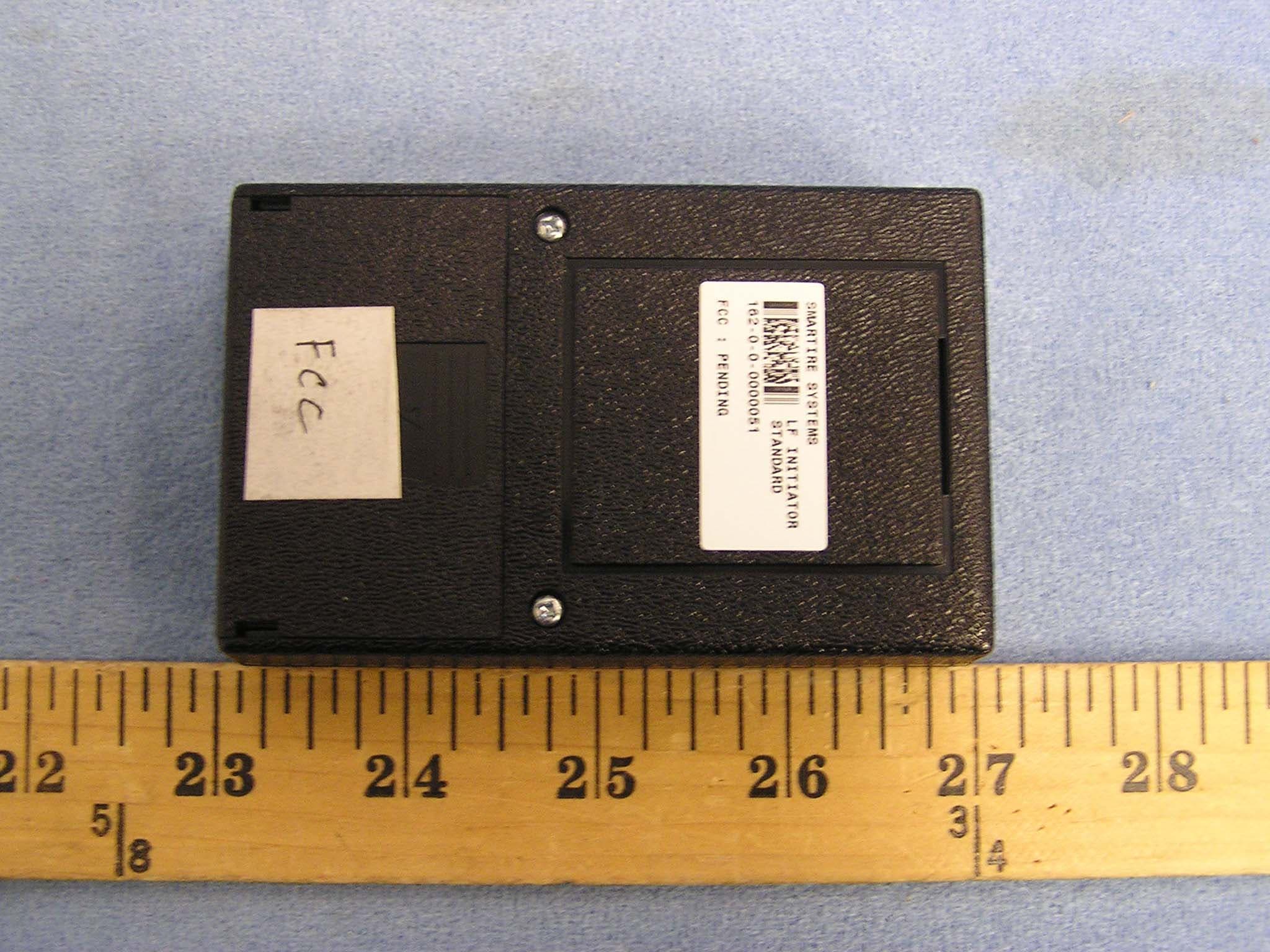
NATLF0162
Jan 06, 2005LF Initiation Tool, 125 kHz LF Transmitter
Equipment Class
DCD - Part 15 Low Power Transmitter Below 1705 kHz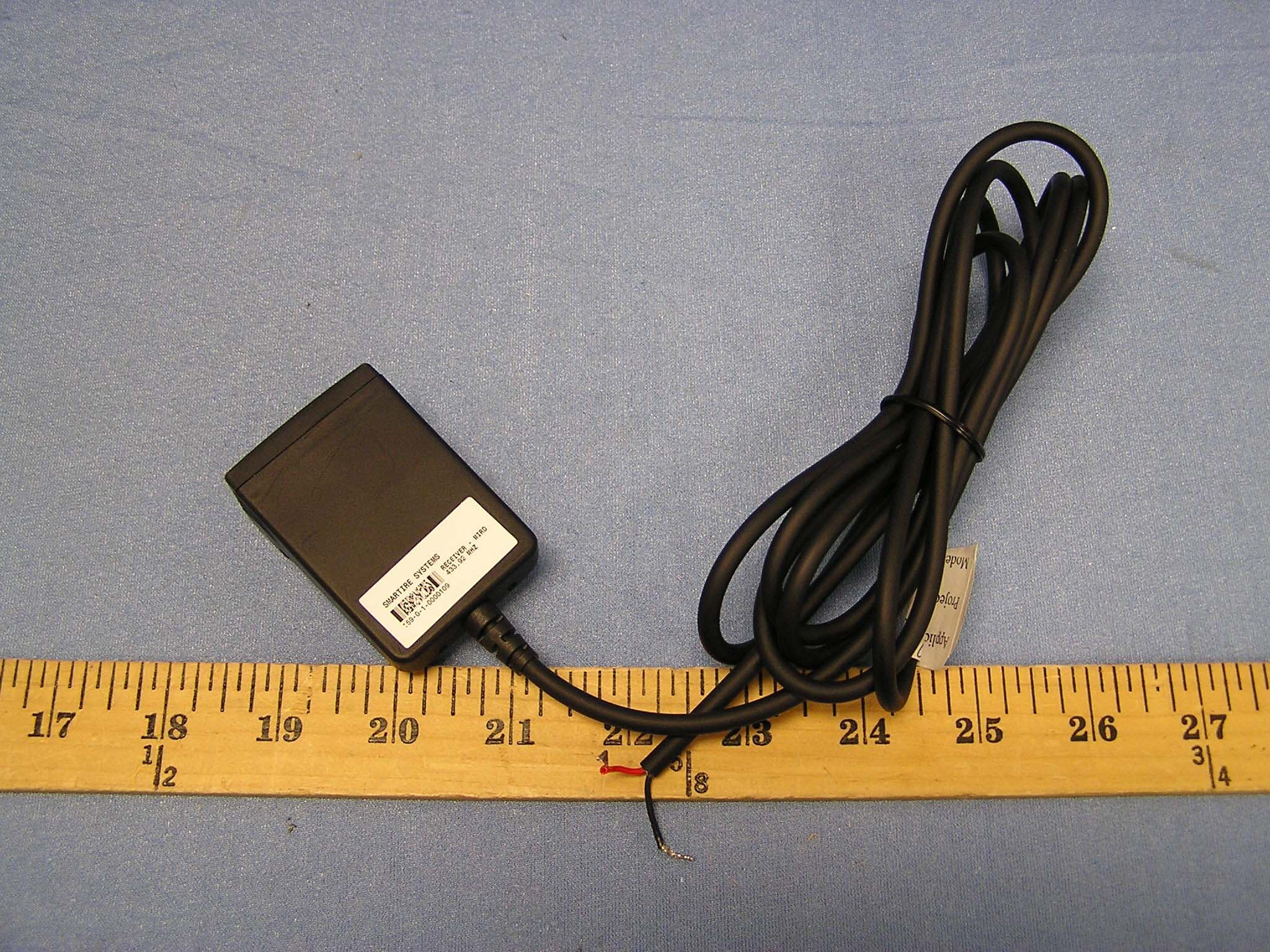
NATMIRD433
Jun 07, 2004433.92MHz Receiver
Equipment Class
CYY - Communications Receiver used w/Pt 15 Transmitter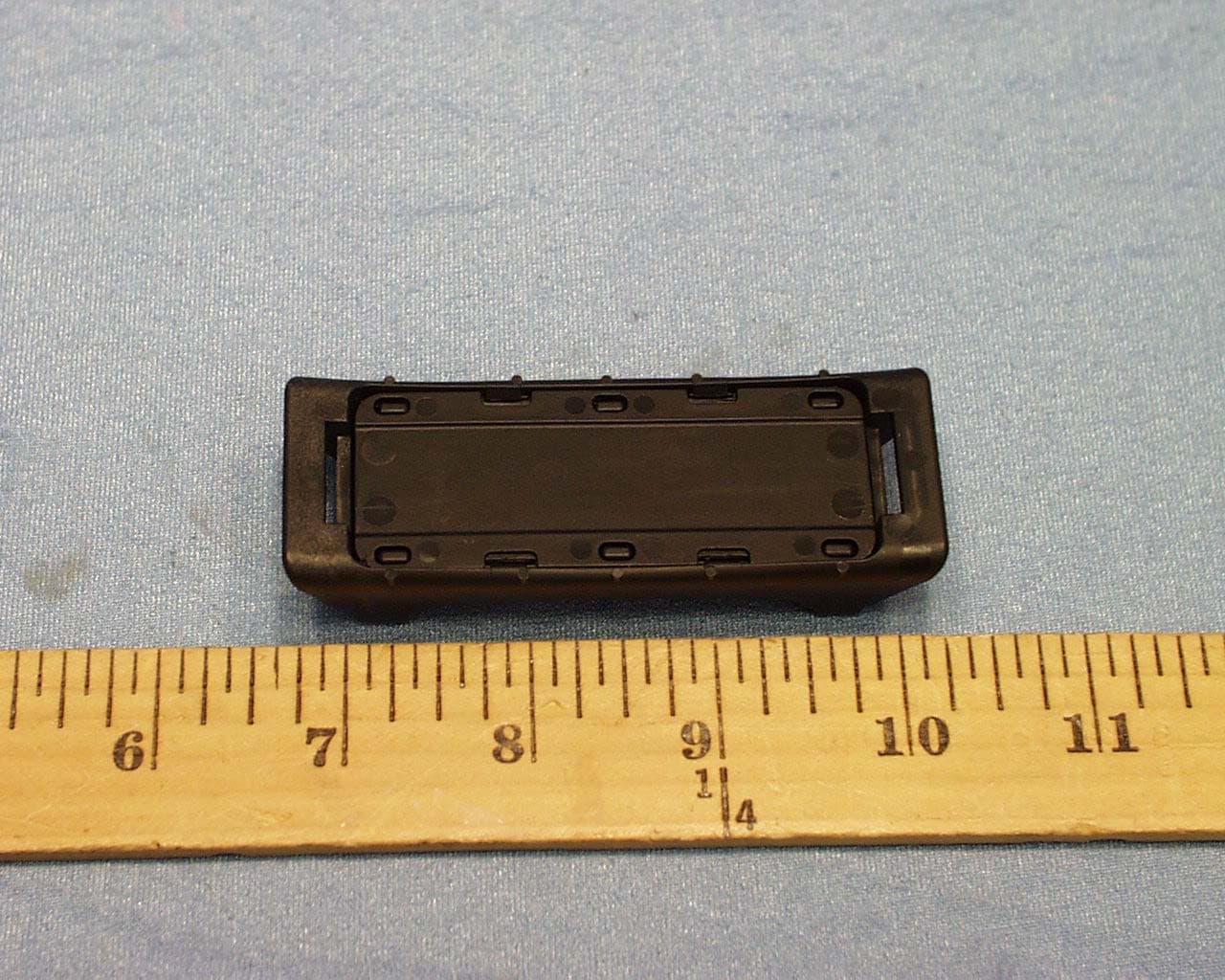
NATTX433CS-3
Jun 03, 2004Tire Monitoring Sensor
Equipment Class
DSC - Part 15 Security/Remote Control Transmitter
NATRX433-RV-1
Apr 09, 2003Tire Monitoring System-Display Receiver
Equipment Class
CYY - Communications Receiver used w/Pt 15 Transmitter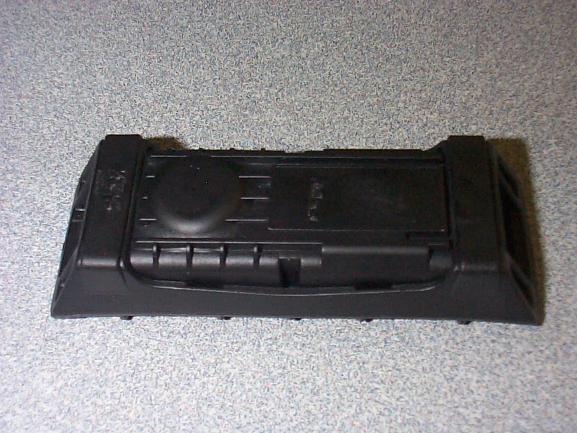
NATTX433CS-2
Apr 08, 2003Tire Monitoring Sensor
Equipment Class
DSR - Part 15 Remote Control/Security Device Transceiver