NKH9510Smart Wireless Access Point 802.11b
Madge Ltd.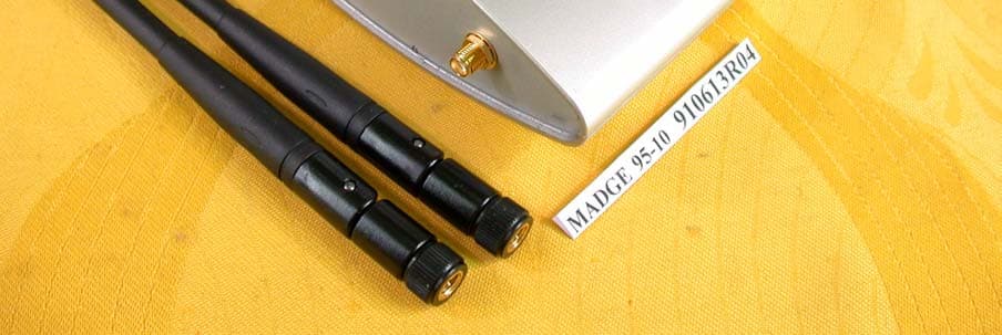
Click to zoom
Application Details
- Equipment Class
- DTS - Digital Transmission System
- Date of Grant
- Jul 17, 2002
- Application Purpose
- Original Equipment
- Date of Application
- Jul 17, 2002
- Equipment Note
- Smart Wireless Access Point 802.11b
- Frequency Range
- 2412.00000000 - 2462.00000000
- Company
- Madge Ltd.
- Country
- United Kingdom
Documents & Files
Document Text
Text extracted from the exhibit documents filed with the FCC. Open a document above to read the original.
Users Manual
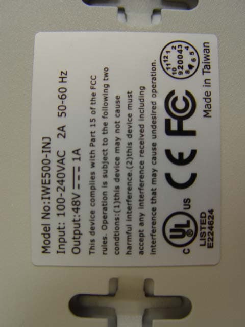
Inform Letter Dear Customer, According to FCC’s regulation, the following Declaration of Conformity has to be made by a company located in USA. They are: This device has been confirmed to be in compliance with the requirements of ANSI C63.4 & FCC part 15 regulations. The test result has been shown in the ADT test report with number RF910613R04. And this compliance is subject to the following two conditions: (1) This device may not cause harmful interference and, (2) This device must accept any interference received, including interference that may cause undesired operation. This declaration can be a separate sheet and be sure that the following message will be also included in this declaration: 1) Product name, model name and trade name. 2) Company name, and address of the one who is responsible for this declaration. 3) Name, title, telephone and fax number as well as the signature of the contact person. Thanks for your attention.
Users Manual
Smart Wireless Access Point 802.11b User’s Guide Version: 2.3 Last Updated: 06/05/2002 i Federal Communication Commission Interference Statement This equipment has been tested and found to comply with the limits for a Class B digital device, pur- suant to Part 15 of the FCC Rules. These limits are designed to provide reasonable protection against harmful interference in a residential installation. This equipment generates, uses and can radiated ra- dio frequency energy and, if not installed and used in accordance with the instructions, may cause harmful interference to radio communications. However, there is no guarantee that interference will not occur in a particular installation. If this equipment does cause harmful interference to radio or television reception, which can be determined by turning the equipment off and on, the user is en- couraged to try to correct the interference by one of the following measures: l Reorient or relocate the receiving antenna. l Increase the separation between the equipment and receiver. l Connect the equipment into an outlet on a circuit different from that to which the receiver is connected. l Consult the dealer or an experienced radio/TV technician for help. FCC Caution: To assure continued compliance. Any changes or modifications not expressly ap- proved by the party responsible for compliance could void the user’s authority to operate this equip- ment. This transmitter must not be co-located or operating in conjunction with any other antenna or trans- mitter. FCC Radiation Exposure Statement This equipment complies with FCC radiation exposure limits set forth for an uncontrolled environ- ment. This equipment should be installed and operated with minimum distance 20 cm between the radiator & your body. This device complies with Part 15 of the FCC Rules. Operation is subject to the following two condi- tions: (1) This device may not cause harmful interference, and (2) this device must accept any inter- ference received, including interference that may cause undesired operation. R&TTE Compliance Statement This equipment complies with all the requirements of DIRECTIVE 1999/5/CE OF THE EUROPEAN PARLIAMENT AND THE COUNCIL OF 9 March 1999 on radio equipment and telecommunication terminal Equipment and the mutual recognition of their conformity ( R&TTE) The R&TTE Directive repeals and replaces in the directive 98/13/EEC(Telecommunications Terminal Equipment and Satellite Earth Station Equipment) As of April 8,2000. ii Safety This equipment is designed with the utmost care for the safety of those who install and use it. However, special attention must be paid to the dangers of electric shock and static electricity when working with electrical equipment. All guidelines of this and of the computer manufacture must therefore be allowed at all times to ensure the safe use of the equipment. EU Countries Intended for Use The ETSI version of this device is intended for home and office use in Austria, Belgium, Denmark , Finland , France ( with Frequency channel restrictions). Germany ,Greece, Ireland , Italy , Luxem- bourg, Portugal , Spain , Sweden, The Netherlands, United Kingdom. The ETSI version of this device is also authorized for use in EFTA member states Norway and Switzerland. EU Countries Not intended for use None. Potential restrictive use France: Only channels 10,11,12 ,and 13 iii Mounting instruction 1. Stick the accessorial sticker for wall-mounting on the wall. 2. Use a φ6.5mm driller to drill a 25mm-deep hole at each of the cross marks. 3. Plug in an accessorial plastic conical anchor in each hole. 4. Screw an accessorial screw in each plastic conical anchor for a proper depth so that the wireless AP can be hung on the screws. 5. Hang the wireless AP on the screws. 55mm 6.5mmST 3.9*16mm iv Power Selection. The AP can be powered by the supplied power adapter or POE (Power over Ethernet). The AP automatically selects the suitable one depending on the user's decision. To power the AP by the supplied power adapter: 1. Plug the power adapter to an AC socket. 2. Plug the connector of the power adapter to the power jack of the AP. Power Supply Selection Instruction - This product intended to be supplied by a Listed Power Unit, marked “Class 2” or “LPS” and output rated 5 V dc, 1 A minimum” or equivalent statement. To power the AP by POE: 1. Plug one connector of an Ethernet cable to an available port of an active Ethernet switch which can supply power over Ethernet. 2. Plug the other connector of the Ethernet cable to the LAN/Config port of the AP. v Table of Contents 1. Introduction.......................................................................................................................1 1.1. Overview.................................................................................................................1 1.2. Features.................................................................................................................1 2. First-Time Installation and Configuration...........................................................................2 2.1. Inserting the Accompanying PCMCIA WLAN Card.................................................2 2.2. Preparing for Configuration.....................................................................................2 2.2.1. Connecting the Managing Computer and the AP..........................................2 2.2.2. Changing the TCP/IP Settings of the Managing Computer...........................3 2.3. Configuring the AP..................................................................................................3 2.3.1. Entering the User Name and Password........................................................4 2.3.2. Step 1: Configure TCP/IP Settings................................................................5 2.3.3. Step 2: Configure IEEE 802.11 Settings.......................................................6 2.3.4. Step 3: Review and Apply Settings.............................…
Text truncated - open the document above for the full version.
Cover Letter(s)
American Telecommunications Certification Body Inc. 6731 Whittier Ave, McLean, VA 22101 July 15, 2002 RE: Madge Networks, Ltd. FCC ID: NKH9510 After a review of the submitted information, I have a few comments on the above referenced Application. 1) Please provide information regarding the internal PCMCIA Card (Model, FCC ID, etc.). This application will be granted only for the particular PCMCIA card utilized in the device. 2) This device is considered both a Part 15 transmitter and a Class B PC Peripheral and is subject to the labeling and users manual requirements for both. The DOC labeling on the device should usually include the phrases "Tested to Comply With FCC Standards" and "FOR HOME OR OFFICE USE". Please update the label to include this. 3) Please confirm if this device is being submitted under equipment code DSS or DTS. 4) Regarding the Transmitter Schematics, please provide one of the following: a) A schematic of the RF portion (PCMCIA Card). b) Alternatively, if the radio is a modular component from a different manufacturer, you may instead provide a parts list that shows the PCMCIA Card as a part from a different manufacturer. If the parts list is provided, please be sure to let us know if confidentiality is requested on it and update the confidentiality letter if necessary. 5) The users manual cautions to use only shielded interface cables (page 2 of 28), but it is not clear if the ethernet cable is to be shielded or not. Please comment and/or clarify this issue in the manual. 6) There does not appear to be any spurious emissions data measured above the fundamental frequency. Please confirm the highest frequency measured to. Timothy R. Johnson Examining Engineer mailto: [email protected] The items indicated above must be submitted before processing can continue on the above referenced application. Failure to provide the requested information may result in application termination. Correspondence should be considered part of the permanent submission and may be viewed from the Internet after a Grant of Equipment Authorization is issued. Please do not respond to this correspondence using the email reply button. In order for your response to be processed expeditiously, you must submit your documents through the AmericanTCB.com website. Also, please note that partial responses increase processing time and should not be submitted. Any questions about the content of this correspondence should be directed to the sender.
Cover Letter(s)
Dear Tim, For item 1, this project applied as end product (AP with PCMCIA card together). For item 2, 3, 4, 5, please see revised file which has been uploaded on the website. For item 6, we had verified the emission frequency above fundamental frequency, but the emission level was too low to be detected. Thank you, Rennie ----- Âà§eªÌ Rennie Wang/ADT ©ó 2002/07/19 09:47 AM ----- "Timothy R. Johnson" ¦¬¥ó¤H¡G [email protected] <tjohnson@Americ °Æ¥»§Û°e¡G [email protected], [email protected] anTCB.com> ¥D¦®¡G Review of Madge Networks Ltd., FCC ID: NKH9510 2002/07/16 11:41 AM Alan, Attached are comments regarding review of this application. Please provide information as soon as possible. Thank You, Timothy R. Johnson NARTE Certified EMC Engineer No. EMC-002205-NE email: [email protected] alternate email: [email protected] (See attached file: ATCB Comments 071502.pdf) To: [email protected] Subject: Review of Madge Networks Ltd., FCC ID: NKH9510 7/18/2002file://C:\DOCUME~1\TIMOTH~1.JOH\LOCALS~1\Temp\eudB.htm =big5BQVRDQiBDb21tZW50cyAwNzE1MDIucGRm=2.pdf 7/18/2002file://C:\DOCUME~1\TIMOTH~1.JOH\LOCALS~1\Temp\eudB.htm
External Photos
Page 1 ANNEX PHOTOGRAPHS OF EUT Page 2 Page 3 Page 4
ID Label/Location Info
9510l.bmp (619x486x24b bmp)
Internal Photos
Page 5 Page 6 Page 7 Page 8 Page 9 Page 10 Page 11 Page 12 Page 13 Page 14 Page 15
Operational Description
FCC ID: NKH9510 ADT No.910613R04 Operational Description The transmitter of the EUT is powered by power adapter or POE (Power over Ethernet) and connected with managing computer through RJ45 port. The antenna type is Dipole antenna with Reversed SMA connector. Under normal use condition, the user has to keep at least 20cm separation distance between radiator and the body of the user. The other instruction, please have a look at the users manual. DSSS Information This device is Direct Sequence Spread Spectrum, the data is mixed by pseudorandom code which is an orthogonal code. The mixed data is digital modulated by BPSK and QPSK technique depends on the data rates. The CCK coding is applied for increasing the data rate, and also the processing gain will be increased. The bit rates are 1,2,5.5,11Mbps, the symbol rates are 1,1,1.375,1.375Mbps, the chip rates are always 11Mbps. So, the Chip/symbol is 11,11,8 and 8 respectively. Although is higher bit rate, the processing gain is lower than 10, but the CCK coding used in higher bit rate will provide 2.2dB coding gain.
RF Exposure Info
FCC ID: NKH9510 ADT No.: 910613R04 FCC TEST REPORT REPORT NO.: RF910613R04 MODEL NO.: 95-10 ACCORDING: FCC Guidelines for Human Exposure IEEE C95.1 APPLICANT:Madge Networks Ltd. ADDRESS: Wexham Springs, Framewood Road, Wexham, Slough, SL3 6PJ, England ISSUED BY:Advance Data Technology Corporation LAB LOCATION:47 14th Lin, Chiapau Tsun, Linko, Taipei, Taiwan, R.O.C. 0528 Lab Code: 200102-0 FCC ID: NKH9510 ADT No.: 910613R04 RF Exposure Measurement (Mobile Device) 1. Introduction 2.4GHz frequency band is regarded specially as a dangerous band for its heating harmfulness to the human body. That’s why microwave oven is operating in this frequency band. The manufacturer whose product is working in this frequency band is obligatory to prove the harmfulness of his product. In this document, we try to prove the safety of radiation harmfulness to the human body for our product. The limit for Maximum Permissible Exposure (MPE) specified in FCC 1.1310 is followed. The Gain of the antenna used in this product is measured in a Fully Anechoic Chamber (FAC), and the maximum total power input to the antenna is measured. Through the Friis transmission formula and the maximum gain of the antenna, we can calculate the distance, away from the product, where the limit of MPE is reached. 2. Classification The antenna of the product, under normal use condition, is at least 20cm away from the body of the user. Warning statement for keeping 20cm separation distance and the prohibition of operating next to a person has been printed on the users manual. So, this product is classified as the Mobile Device. 3. RF Exposure Limit According to FCC 1.1310: The criteria listed in the following table shall be used to evaluate the environmental impact of human exposure to radio-frequency (RF) radiation as specified in 1.1307(b). FCC ID: NKH9510 ADT No.: 910613R04 LIMITS FOR MAXIMUM PERMISSIBLE EXPOSURE (MPE) Frequency Range (MHz) Electric Field Strength (V/m) Magnetic Field Strength (A/m) Power Density (mW/cm 2 ) Average Time (minutes) (A)Limits For Occupational / Control Exposures 30-30061.40.1631.06 300-1500......F/3006 1500-100,000......56 (B)Limits For General Population / Uncontrolled Exposure 30-30027.50.0730.230 300-1500......F/150030 1500-100,000......1.030 F = Frequency in MHz 4. Friis Formula Friis transmission formula : Pd = (Pout*G) / (4*pi*r 2 ) where Pd = power density in mW/cm 2 Pout = output power to antenna in mW G = gain of antenna in linear scale Pi = 3.1416 R = distance between observation point and center of the radiator in cm Pd is the limit of MPE, 1 mW/cm 2 . If we know the maximum Gain of the antenna and the total power input to the antenna, through the calculation, we will know the distance r where the MPE limit is reached. Ref. : David K. Cheng, Field and Wave Electromagnetics, Second Edition, Page 640, Eq. (11-133). 5. EUT Operating condition The software provided by Manufacturer enabled the EUT to transmit and receive data at lowest, middle and highest channel individually. FCC ID: NKH9510 ADT No.: 910613R04 6. Test Results 6.1 Antenna Gain The maximum Gain measured in Fully Anechoic Chamber is 2dBi or 1.58 (numeric). 6.2 Output Power Into Antenna & RF Exposure Distance : CHANNEL CHANNEL FREQUENCY (MHz) OUTPUT POWER TO ANTENNA (mW) MINIMUM ALLOWABLE DISTANCE ( r ) FROM SKIN (Centi-Meter) 1241233.342.05 6243732.512.02 11246231.622.00 The minimum allowable distance is very close to the enclosure of the antenna. So, the user has no need to worry about the harmfulness of radiation. But it is recommended to always keep, at least, 20cm separation distance with the antenna.
Test Report
FCC ID: NKH9510 Report No.: RF910613R041Issued: July 9, 2002 FCC TEST REPORT REPORT NO.: RF910613R04 MODEL NO.: 95-10 RECEIVED: June 13, 2002 TESTED: June 20 ~ June 27, 2002 APPLICANT: Madge Networks Ltd. ADDRESS: Wexham Springs, Framewood Road, Wexham, Slough, SL3 6PJ, England ISSUED BY: Advance Data Technology Corporation LAB LOCATION: 47 14 th Lin, Chiapau Tsun, Linko, Taipei, Taiwan, R.O.C. This test report consists of 58 pages in total. It may be duplicated completely for legal use with the approval of the applicant. It should not be reproduced except in full, without the written approval of our laboratory. The client should not use it to claim product endorsement by CNLA, NVLAP or any government agencies. The test results in the report only apply to the tested sample. 0528 ILAC MRA Lab Code: 200102-0 FCC ID: NKH9510 Report No.: RF910613R042Issued: July 9, 2002 Table of Contents 1CERTIFICATION .................................................................................................................... 4 2SUMMARY OF TEST RESULTS............................................................................................ 5 3GENERAL INFORMATION .................................................................................................... 6 3.1GENERAL DESCRIPTION OF EUT....................................................................................... 6 3.2DESCRIPTION OF TEST MODES......................................................................................... 7 3.3GENERAL DESCRIPTION OF APPLIED STANDARDS........................................................ 7 3.4DESCRIPTION OF SUPPORT UNITS................................................................................... 8 4TEST TYPES AND RESULTS ................................................................................................ 9 4.1CONDUCTED EMISSION MEASUREMENT......................................................................... 9 4.1.1LIMITS OF CONDUCTED EMISSION MEASUREMENT ...................................................... 9 4.1.2TEST INSTRUMENTS ...........................................................................................................9 4.1.3TEST PROCEDURES .......................................................................................................... 10 4.1.4DEVIATION FROM TEST STANDARD ................................................................................ 10 4.1.5TEST SETUP ....................................................................................................................... 11 4.1.6EUT OPERATING CONDITIONS......................................................................................... 12 4.1.7TEST RESULTS (A) ............................................................................................................. 13 4.1.8TEST RESULTS (B) ............................................................................................................. 19 4.2RADIATED EMISSION MEASUREMENT............................................................................ 25 4.2.1LIMITS OF RADIATED EMISSION MEASUREMENT ......................................................... 25 4.2.2TEST INSTRUMENTS ......................................................................................................... 26 4.2.3TEST PROCEDURES .......................................................................................................... 27 4.2.4DEVIATION FROM TEST STANDARD ................................................................................ 27 4.2.5TEST SETUP ....................................................................................................................... 28 4.2.6EUT OPERATING CONDITIONS......................................................................................... 28 4.2.7TEST RESULTS (A) ............................................................................................................. 29 4.2.8TEST RESULTS (B) ............................................................................................................. 31 4.2.9TEST RESULTS ................................................................................................................... 33 4.36dB BANDWIDTH MEASUREMENT ................................................................................... 36 4.3.1LIMITS OF 6dB BANDWIDTH MEASUREMENT ................................................................ 36 4.3.2TEST INSTRUMENTS ......................................................................................................... 36 4.3.3TEST PROCEDURE ............................................................................................................37 4.3.4DEVIATION FROM TEST STANDARD ................................................................................ 37 4.3.5TEST SETUP ....................................................................................................................... 37 4.3.6EUT OPERATING CONDITIONS......................................................................................... 37 4.3.7TEST RESULTS ................................................................................................................... 38 4.4MAXIMUM PEAK OUTPUT POWER ................................................................................... 42 4.4.1LIMITS OF MAXIMUM PEAK OUTPUT POWER MEASUREMENT ................................... 42 4.4.2INSTRUMENTS.................................................................................................................... 42 4.4.3TEST PROCEDURES .......................................................................................................... 43 4.4.4DEVIATION FROM TEST STANDARD ................................................................................ 43 4.4.5TEST SETUP ....................................................................................................................... 43 4.4.6EUT OPERATING CO…
Text truncated - open the document above for the full version.
Test Report
FCC ID: NKH9510 Report No.: RF910613R0436Issued: July 9, 2002 4.3 6dB BANDWIDTH MEASUREMENT 4.3.1 LIMITS OF 6dB BANDWIDTH MEASUREMENT The minimum of 6dB Bandwidth Measurement is 0.5 MHz. 4.3.2 TEST INSTRUMENTS Description & ManufacturerModel No.Serial No.Calibrated Until SPECTRUM ANALYZERFSEK30100049July 17, 2002 NOTE: 1.The measurement uncertainty is less than +/- 2.6dB, which is calculated as per the NAMAS document NIS81. 2.The calibration interval of the above test instruments is 12 months and the calibrations are traceable to NML/ROC and NIST/USA. FCC ID: NKH9510 Report No.: RF910613R0437Issued: July 9, 2002 4.3.3 TEST PROCEDURE The transmitter output was connected to the spectrum analyzer through an attenuator. The bandwidth of the fundamental frequency was measured by spectrum analyzer with 100 kHz RBW and 100 kHz VBW. The 6 dB bandwidth is defined as the total spectrum the power of which is higher than peak power minus 6 dB. 4.3.4 DEVIATION FROM TEST STANDARD No deviation 4.3.5 TEST SETUP 4.3.6 EUT OPERATING CONDITIONS The software provided by client to enable the EUT under transmission condition continuously at lowest, middle and highest channel frequencies individually. EUT SPECTRUM ANALYZER FCC ID: NKH9510 Report No.: RF910613R0438Issued: July 9, 2002 4.3.7 TEST RESULTS EUT Smart Wireless Access Point 802.11b MODEL 95-10 INPUT POWER (SYSTEM) 120Vac, 60Hz ENVIRONMENTA L CONDITIONS 25 deg. C, 64%RH, 1005 hPa TESTED BY: Steven Lu CHANNEL CHANNEL FREQUENCY (MHz) 6 dB BANDWIDTH (MHz) MINIMUM LIMIT (MHz) PASS/FAIL 1241210.440.5PASS 6243710.440.5PASS 11246210.440.5PASS FCC ID: NKH9510 Report No.: RF910613R0439Issued: July 9, 2002 CH1 FCC ID: NKH9510 Report No.: RF910613R0440Issued: July 9, 2002 CH6 FCC ID: NKH9510 Report No.: RF910613R0441Issued: July 9, 2002 CH11 FCC ID: NKH9510 Report No.: RF910613R0442Issued: July 9, 2002 4.4 MAXIMUM PEAK OUTPUT POWER 4.4.1 LIMITS OF MAXIMUM PEAK OUTPUT POWER MEASUREMENT The Maximum Peak Output Power Measurement is 30dBm. 4.4.2 INSTRUMENTS Description & ManufacturerModel No.Serial No.Calibrated Until SINGLE CHANNEL POWER METER NRVS100026Feb. 21, 2002 PEAK POWER SENSORNRV-Z32100013May 23,2002 NOTE: 1. The measurement uncertainty is less than +/- 2.6dB, which is calculated as per the NAMAS document NIS81. 2. The calibration interval of the above test instruments is 12 months and the calibrations are traceable to NML/ROC and NIST/USA. FCC ID: NKH9510 Report No.: RF910613R0443Issued: July 9, 2002 4.4.3 TEST PROCEDURES 1. The transmitter output was connected to the peak power meter. 4.4.4 DEVIATION FROM TEST STANDARD No deviation 4.4.5 TEST SETUP 4.4.6 EUT OPERATING CONDITIONS Same as Item 4.3.6 EUTPeak Power Meter FCC ID: NKH9510 Report No.: RF910613R0444Issued: July 9, 2002 4.4.7 TEST RESULTS EUT Smart Wireless Access Point 802.11b MODEL 95-10 INPUT POWER (SYSTEM) 120Vac, 60Hz ENVIRONMENTAL CONDITIONS 25 deg. C, 64%RH, 1005 hPa TESTED BY: Steven Lu CHANNEL CHANNEL FREQUENCY (MHz) PEAK POWER OUTPUT (dBm) PEAK POWER LIMIT (dBm) PASS/FAIL 1241215.2330PASS 6243715.1230PASS 11246215.0030PASS FCC ID: NKH9510 Report No.: RF910613R0445Issued: July 9, 2002 4.5 POWER SPECTRAL DENSITY MEASUREMENT 4.5.1 LIMITS OF POWER SPECTRAL DENSITY MEASUREMENT The Maximum of Power Spectral Density Measurement is 8dBm. 4.5.2 TEST INSTRUMENTS Description & ManufacturerModel No.Serial No.Calibrated Until SPECTRUM ANALYZERFSEK30100049July 17, 2002 NOTE: 1. The measurement uncertainty is less than +/- 2.6dB, which is calculated as per the NAMAS document NIS81. 2. The calibration interval of the above test instruments is 12 months and the calibrations are traceable to NML/ROC and NIST/USA. FCC ID: NKH9510 Report No.: RF910613R0446Issued: July 9, 2002 4.5.3 TEST PROCEDURE The transmitter output was connected to the spectrum analyzer through an attenuator, the bandwidth of the fundamental frequency was measured with the spectrum analyzer using 3 kHz RBW and 30 kHz VBW, set sweep time = span/3 kHz. The power spectral density was measured and recorded. The sweep time is allowed to be longer than span/3 kHz for a full response of the mixer in the spectrum analyzer. 4.5.4 DEVIATION FROM TEST STANDARD No deviation 4.5.5 TEST SETUP 4.5.6 EUT OPERATING CONDITION Same as Item 4.3.6 EUT SPECTRUM ANALYZER FCC ID: NKH9510 Report No.: RF910613R0447Issued: July 9, 2002 4.5.7 TEST RESULTS EUT Smart Wireless Access Point 802.11b MODEL 95-10 INPUT POWER (SYSTEM) 120Vac, 60Hz ENVIRONMENTAL CONDITIONS 25 deg. C, 64%RH, 1005 hPa TESTED BY: Steven Lu CHANNEL NUMBER CHANNEL FREQUENCY (MHz ) RF POWER LEVEL IN 3 kHz BW (dBm) MAXIMUM LIMIT (dBm) PASS/FAIL 12412-11.428PASS 62437-11.788PASS 112462-11.458PASS FCC ID: NKH9510 Report No.: RF910613R0448Issued: July 9, 2002 CH1 FCC ID: NKH9510 Report No.: RF910613R0449Issued: July 9, 2002 CH6 FCC ID: NKH9510 Report No.: RF910613R0450Issued: July 9, 2002 CH11 FCC ID: NKH9510 Report No.: RF910613R0451Issued: July 9, 2002 4.6 BAND EDGES MEASUREMENT 4.6.1 LIMITS OF BAND EDGES MEASUREMENT Below –20dB of the highest emission level of operating band (in 100KHz Resolution Bandwidth). 4.6.2 TEST INSTRUMENTS Description & ManufacturerModel No.Serial No.Calibrated Until SPECTRUM ANALYZERFSEK30100049July 17, 2002 NOTE: 1. The measurement uncertainty is less than +/- 2.6dB, which is calculated as per the NAMAS document NIS81. 2. The calibration interval of the above test instruments is 12 months and the calibrations are traceable to NML/ROC and NIST/USA. 4.6.3 TEST PROCEDURE The transmitter output was connected to the spectrum analyzer via a low lose cable. Set both RBW and VBW of spectrum analyzer to 100 kHz with suitable frequency span including 100 kHz bandwidth from band edge. The band edges was measured and recorded. 4.6.4 DEVIATION FROM TEST STANDARD No deviation FCC ID: NKH9510 Report No.: RF910613R0452Issued: July 9, 2002 4.6.5 EUT OPERATING CONDITION Same as Item 4.3.6 4.6.6 TEST RESULTS The spectrum plots are attached on the following 2 pages. D2 line indicates the h…
Text truncated - open the document above for the full version.
Test Setup Photos
FCC ID: NKH9510 Report No.: RF910613R0456Issued: July 9, 2002 5 PHOTOGRAPHS OF THE TEST CONFIGURATION CONDUCTED EMISSION TEST FCC ID: NKH9510 Report No.: RF910613R0457Issued: July 9, 2002 FCC ID: NKH9510 Report No.: RF910613R0458Issued: July 9, 2002 RADIATED EMISSION TEST FCC ID: NKH9510 Report No.: RF910613R0459Issued: July 9, 2002
Contact Information
Applicant
Bob Lindsey(VP Operations, R&D)
Technical Contact
Advance Data Technology CorporationAlan Lane
[email protected]+886-3-327-0910
13-1, Lane 19, WenShan 3rd., St. · Taoyuan · Taiwan
Non-Technical Contact
Advance Data Technology CorporationAlan Lane
[email protected]+886-3-327-0910
Test Firm
Bureau Veritas CPS (H.K.) Ltd. Taoyuan BranchTommy Wu
Technical Specifications
| # | Rule Parts | Frequency Range | Power Output |
|---|---|---|---|
| 1 | 15C | 2.41 GHz - 2.46 GHz | 33.00 mW |
Other Applications from Madge Ltd.
NKH9610
Dec 13, 2004Enterprise Access Point 802.11b/g Dual-Radio
Equipment Class
DTS - Digital Transmission System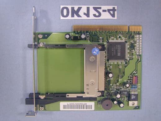
NKH9520
Jul 11, 2002Smart Wireless PCI Adapter 802
Equipment Class
JBP - Part 15 Class B Computing Device Peripheral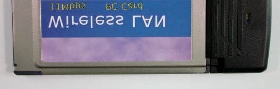
NKH9531
Jul 08, 2002Smart Wireless PCMCIA Adapter 802.11b
Equipment Class
DTS - Digital Transmission System
NKHPCI5
Sep 12, 2000Smart 100/16/4 PCI Ringnode
Equipment Class
JBP - Part 15 Class B Computing Device Peripheral
NKHPCI4
Oct 12, 1999Smart 100/16/4 PCI-HS Ringnode Mk2
Equipment Class
JBP - Part 15 Class B Computing Device Peripheral