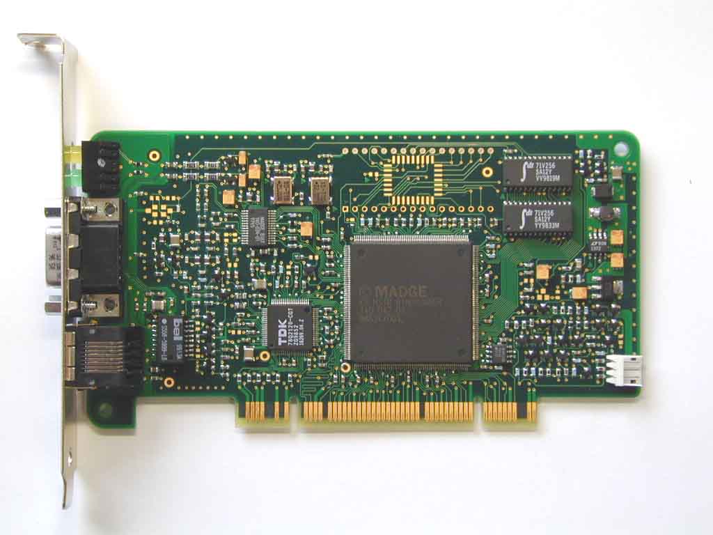
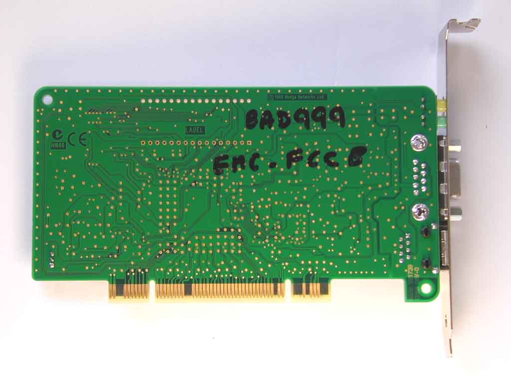
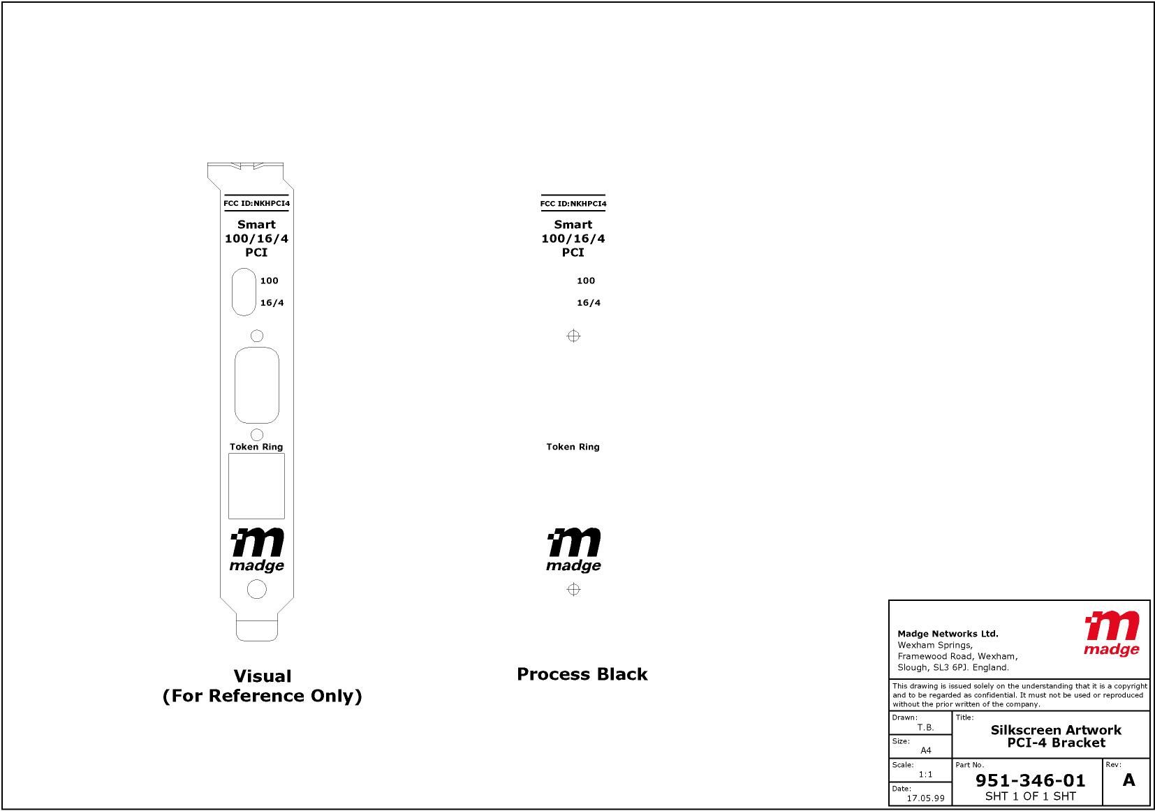
NKHPCI4Smart 100/16/4 PCI-HS Ringnode Mk2
Madge Ltd.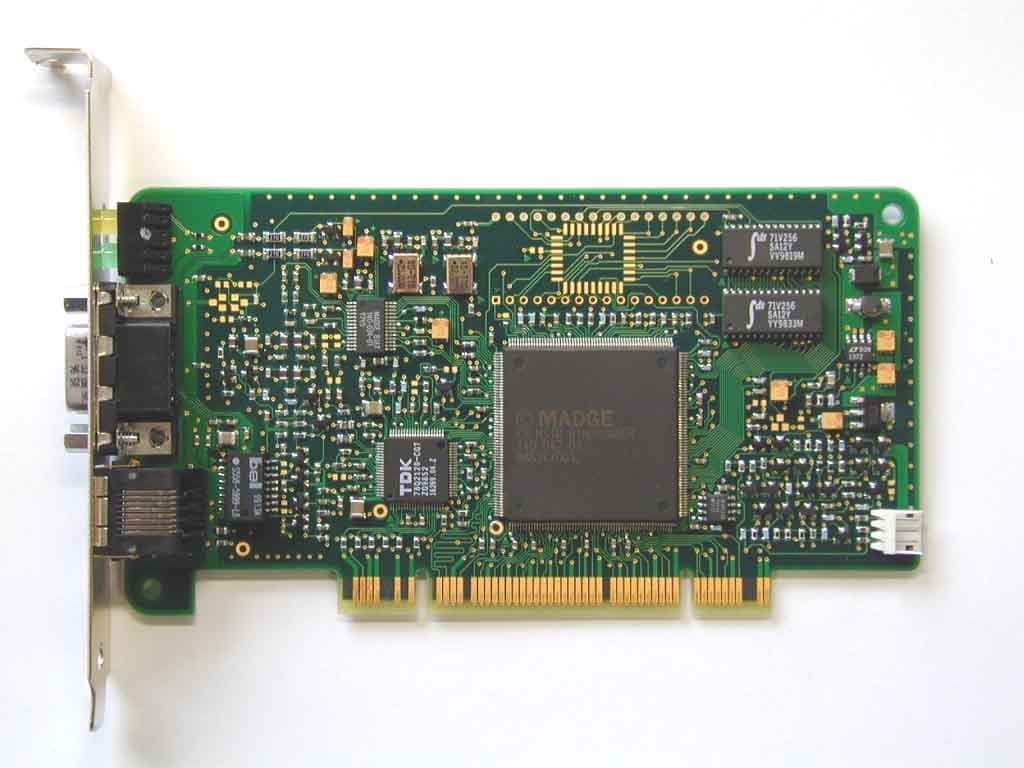
Click to zoom
Application Details
- Equipment Class
- JBP - Part 15 Class B Computing Device Peripheral
- Date of Grant
- Oct 12, 1999
- Application Purpose
- Original Equipment
- Date of Application
- Aug 08, 1999
- Equipment Note
- Smart 100/16/4 PCI-HS Ringnode Mk2
- Company
- Madge Ltd.
- Country
- United Kingdom
Documents & Files
Document Text
Text extracted from the exhibit documents filed with the FCC. Open a document above to read the original.
Users Manual
Installing a Smart 100/16/4 PCI Ringnode Always turn off the power to your computer before installing or removing any adapters. The default ring speed setting for this adapter is 'auto-detect'. This means the adapter will run at the same ring speed as the network (either 100Mbps, 16Mbps, or 4Mbps). To change the default setting, use Madge Assist. This adapter has no switches or links that need setting. PCI computers configure PCI adapters automatically. 1.Read the EMC compliance statement for this adapter. 2.Turn off the power to your computer. 3.Read the handling precautions. 4.Remove the blanking plate from an unused PCI slot. 5.Insert the adapter into the slot and secure it by using the retaining screw from the blanking plate that you removed. 6.Connect a data-cable to the appropriate connector on the adapter: the 9-pin D-type connector for STP cabling or the RJ45 connector for UTP cabling (see Locating the data-cable connectors ). The Smart 100/16/4 PCI Ringnode automatically detects the type of cabling you connect to the adapter. 7.Connect the other end of the data-cable to a working token-ring network. 8.Re-boot the computer. 9.Run Madge Assist to check that the adapter and its connection are working correctly. (See Configuring and testing adapters with Madge Assist.) The LEDs on the bracket of the Smart 100/16/4 PCI Ringnode indicate the speed of the network into which the adapter is inserted: the yellow LED indicates that the adapter is inserted into an HSTR switch port the green LED indicates that the adapter is inserted into a network running at either 4Mbps or 16Mbps 10.Install the driver software. Note: Caution: Warning: 1 of 109/08/99 16:47 Installing a Smart 100/16/4 PCI Ringnodefile:///D|/Approval/PCI-HS FCC Certification/hs2_inst.htm
Users Manual
EMC compliance statement The statements on this page apply to the following adapters: Smart 16/4 PCI Ringnode Mk2 Smart 16/4 PCI Ringnode Mk3 (WOL) Presto PCI 2000 16/4 CardBus Adapter Mk2 (with Class B certification) Smart 100/16/4 Ringnode MK2 FCC Statement This device complies with Part 15 of the FCC Rules. Operation is subject to the following two conditions: this device may not cause harmful interference this device must accept any interference that may cause undesired operation This equipment has been tested and found to comply with the limits for a Class B digital device, pursuant to Part 15 of the FCC Rules. These limits are designed to provide reasonable protection against harmful interference in a residential installation. This equipment generates, uses and can radiate radio frequency energy and, if not installed and used in accordance with the instructions, may cause harmful interference to radio communications. However, there is no guarantee that interference will not occur in a particular installation. If this equipment does cause harmful interference to radio or television reception, which can be determined by turning the equipment off and on, the user is encouraged to try to correct the interference by one or more of the following measures: reorient or relocate the receiving antenna increase the separation between the equipment and the receiver connect the equipment into an outlet on a circuit different from that to which the receiver is connected consult the dealer or an experienced radio/TV technician for help The user is advised that any modification to the board not expressly authorised by the manufacturer may void the user's authority to operate this device. Canadian Statement This Class A digital apparatus meets all the requirements of the Canadian Interference-Causing Equipment Regulations. Cet appareil numérique de la classe A respecte toutes les exigences du Règlement sur le matériel brouilleur du Canada. European EMC Directive This product carries the CE mark to indicate that it meets the requirements of the European Directive on Electromagnetic Compatibility (89/336/EEC). It has been tested to the following standards: EN55022:1994, EN50082-1:1992. For operation in commercial or industrial environments (Class A), there are no restrictions on cable types that can be used. 1 of 109/08/99 16:47 EMC compliance statementfile:///D|/Approval/PCI-HS FCC Certification/emc2.htm
Users Manual
Installing a Smart 100/16/4 PCI Ringnode WARNING- Always turn off the power to your computer before installing or removing any adapters. CAUTION - The default ring speed setting for this adapter is 'auto-detect'. This means the adapter will run at the same ring speed as the network (either 100Mbps, 16Mbps, or 4Mbps). To change the default setting, use Madge Assist. NOTE- This adapter has no switches or links that need setting. PCI computers configure PCI adapters automatically. 1.Read the EMC compliance statement for this adapter. 2.Turn off the power to your computer. 3.Read the handling precautions. 4.Remove the blanking plate from an unused PCI slot. 5.Insert the adapter into the slot and secure it by using the retaining screw from the blanking plate that you removed. 6.Connect a data-cable to the appropriate connector on the adapter: the 9-pin D-type connector for STP cabling or the RJ45 connector for UTP cabling (see Locating the data-cable connectors). The Smart 100/16/4 PCI Ringnode automatically detects the type of cabling you connect to the adapter. 7.Connect the other end of the data-cable to a working token-ring network. 8.Re-boot the computer. 9.Run Madge Assist to check that the adapter and its connection are working correctly. (See Configuring and testing adapters with Madge Assist.) The LEDs on the bracket of the Smart 100/16/4 PCI Ringnode indicate the speed of the network into which the adapter is inserted: the yellow LED indicates that the adapter is inserted into an HSTR switch port the green LED indicates that the adapter is inserted into a network running at either 4Mbps or 16Mbps 10.Install the driver software. EMC compliance statement The statements on this page apply to the following adapters: - Smart 16/4 PCI Ringnode Mk2 - Smart 16/4 PCI Ringnode Mk3 (WOL) - Presto PCI 2000 - 16/4 CardBus Adapter Mk2 (with Class B certification) - Smart 100/16/4 Ringnode MK2 FCC Statement This device complies with Part 15 of the FCC Rules. Operation is subject to the following two conditions: - this device may not cause harmful interference - this device must accept any interference that may cause undesired operation This equipment has been tested and found to comply with the limits for a Class B digital device, pursuant to Part 15 of the FCC Rules. These limits are designed to provide reasonable protection against harmful interference in a residential installation. This equipment generates, uses and can radiate radio frequency energy and, if not installed and used in accordance with the instructions, may cause harmful interference to radio communications. However, there is no guarantee that interference will not occur in a particular installation. If this equipment does cause harmful interference to radio or television reception, which can be determined by turning the equipment off and on, the user is encouraged to try to correct the interference by one or more of the following measures: - reorient or relocate the receiving antenna - increase the separation between the equipment and the receiver - connect the equipment into an outlet on a circuit different from that to which the receiver is connected - consult the dealer or an experienced radio/TV technician for help The user is advised that any modification to the board not expressly authorised by the manufacturer may void the user's authority to operate this device.
Parts List/Tune Up Info
Bill Of Materials for pci446.sch on Tue Jul 20 09:43:23 1999 -------------------------------------------------------------------------------- ------------------------------------------------------------- Qty Ref-Des Madge P/N. PCB Site Part Type Additional Part Info. Description -------------------------------------------------------------------------------- ------------------------------------------------------------- 322 TP1-322 TP40 TP TEST PAD 78 H1-78 TP26 TP26 SMALL TEST PAD DO NOT USE 1 U1 140-034-01 DIP28/SSOP BLUEBIRD BLUEBIRD ASIC SSSB167 BLUEBIRD TOKEN RING INTERFACE 1 U3 140-042-01 FPT240 KNOSSOS3 STANDARD CELL ASIC K3 1 MX1 151-141-01 N/A /BRACKET BRKT PCI4 MARK 2 CARD RETAINING BRACKET 1 MX2 151-323-06 N/A /PCB MAN- SPEC 952-353-06 PCB FROM ARTWORK 952-352-06 1 U2 20000394 TQFP80 78Q2120CGT 78Q2120CGT 10/100BASE-TX ETHERNET TRANSCEIVER 1 U6 20000416 DIP8/SO SERIAL/EEPROM 93C46 SERIAL EEPROM USE BIA SPEC.960-003-07 2 U7-8 20000442 DIP28/SOJ/300 SRAM32KX8 32K X 8 STATIC RAM 3.3V 3 Q20 Q28-29 21000320 SOT23N PNP/SOT23A FMMT717 PNP TRANSISTOR 1 CR4 21000332 SMBJ CR/SCHOTTKY MBRS130LT3 SCHOTTKY DIODE 1 LED1 21000433 LED2/SSA210 LEDDUAL ??DEVICE??,??MANUF??, DUAL LED ??COLOUR COMB?? 5 C3 C5 C34 C39 C92 22000319 1210 C/CERSM,10U, 16V,Y5V MULTI LAYER CERAMIC CHIP CAPACITOR +80%-20% 2 R32-33 23000107 0603 R/SM,22R,1% 1/16W SURFACE MOUNT RESISTOR 1 R42 23000114 0603 R/SM,1K3,1% 1/16W SURFACE MOUNT RESISTOR 2 R13 R19 23000155 0603 R/SM,390R,1% 1/16W SURFACE MOUNT RESISTOR 14 R24 R67 R69 R94-97 23000224 0603 R/SM,100K,5% 1/16W SURFACE MOUNT RESISTOR R100 R103 R110 R113 R126 R128 R130 1 R39 23000270 0603 R/SM,470K,5% 1/16W SURFACE MOUNT RESISTOR 12 R23 R25-26 R31 23000356 0603 R/SM,62R,1% 1/16W SURFACE MOUNT RESISTOR R61-62 R66 R73-75 R78-79 2 R45 R116 23000446 0603 R/SM,110R,1% 1/16W SURFACE MOUNT RESISTOR 1 T1 26000391 DIP16/SOWIDE TR/EML007 PULSE EML007 HSTR TRANSFORMER 1 X2 28000400 OSC/4/SO OSC/4/SM/E,32MHZ ???PPM,???SIZE CLOCK OSCILLATOR MODULE WITH ENABLE 1 X1 28000439 OSC/4/SO OSC/4/SM/E,25MHZ 50PPM,3.3V SMD TRISTATE CLOCK OSCILLATOR MODULE WITH ENABLE 1 J3 31000321 HDR3RA/WONLAN HDR3RA/WONLAN AMP 173979-3 3 WAY R/A HEADER 2MM PITCH (WAKE-ON-LAN) 2 MX3-4 400-041 N/A /SCREWLOCK UNC 4-40 X 8mm CLEAR FEMALE SCREWLOCK 1 J1 400-100 DCON9/NOSILK CON/D9F 9-PIN FEMALE D-TYPE CONNECTOR 1 J2 422-002 RJ45S CON/RJ45S SHIELDED RJ45-TYPE TELEPHONE SOCKET 1 MX5 425-132 N/A /ICSOCKET 32 PIN DIL SOCKET FOR #1 6 R14 R18 R20 R36-37 527-008 0603 R/SM,100R,1% 1/16W SURFACE MOUNT RESISTOR R80 2 R43-44 527-009 0603 R/SM,1K,1% 1/16W SURFACE MOUNT RESISTOR 13 R17 R22 R56 R59 R63 527-017 0603 R/SM,3K48,1% 1/16W SURFACE MOUNT RESISTOR R81-82 R86 R91-93 R124 R127 5 R1-2 R60 R111 R118 527-019 0603 R/SM,576R,1% 1/16W SURFACE MOUNT RESISTOR 8 R3-6 R11 R21 R30 527-020 0603 R/SM,0R 1/16W SURFACE MOUNT RESISTOR R49 23 R34-35 R50-55 527-025 0603 R/SM,165R,1% 1/16W SURFACE MOUNT RESISTOR R57-58 R65 R68 R70 R76-77 R83-85 R88-90 R119 R125 2 R29 R41 527-026 0603 R/SM,681R,1% 1/16W SURFACE MOUNT RESISTOR 7 R99 R102 R105 R107 527-028 0603 R/SM,6K19,1% 1/16W SURFACE MOUNT RESISTOR R109 R112 R123 4 R9-10 R48 R72 527-036 0603 R/SM,10K,1% 1/16W SURFACE MOUNT RESISTOR 8 R98 R101 R104 527-038 0603 R/SM,18K2,1% 1/16W SURFACE MOUNT RESISTOR R114-115 R117 R120-121 4 R87 R106 R122 R129 528-013 0603 R/SM,2K,5% 1/16W SURFACE MOUNT RESISTOR 4 R15-16 R27-28 553-027 1206 R/SM,27R,5% 1/4W SURFACE MOUNT RESISTOR 2 R46-47 554-048 0805 R/SM,5R6,5% 1/10W SURFACE MOUNT RESISTOR 2 C28-29 675-003 TANT/A C/TNTSM,1U5,10% 16V TANTALUM CHIP CAPACITOR 1 C49 675-004 TANT/B C/TNTSM,6U8,20% 16V TANTALUM CHIP CAPACITOR 6 C22 C35 C86 C89 678-109 TANT/B C/TNTSM,10U,20% 16V TANTALUM CHIP CAPACITOR C93-94 1 C88 681-001 0805 C/CERSM,47N,10% 50V,X7R MULTI LAYER CERAMIC CHIP CAPACITOR 4 C13 C20 C43 C83 683-008 0603 C/CERSM,120P,5% 50V,COG MULTI LAYER CERAMIC CHIP CAPACITOR 54 C1-2 C6 C9-11 C17 683-013 0603 C/CERSM,100N,20% 25V,Y5V MULTI LAYER CERAMIC CHIP CAPACITOR C25-27 C30-33 C38 C40 C42 C44-46 C48 C50-52 C54-62 C64-81 C90-91 C95 1 C87 683-020 0603 C/CERSM,4N7,10% 50V,X7R MULTI LAYER CERAMIC CHIP CAPACITOR 7 C7-8 C12 C14 C19 683-022 0603 C/CERSM,33P,5% 50V,COG MULTI LAYER CERAMIC CHIP CAPACITOR C21 C85 2 C18 C82 683-025 0603 C/CERSM,100P,5% 50V,COG MULTI LAYER CERAMIC CHIP CAPACITOR 6 C4 C36-37 C41 C47 683-026 0603 C/CERSM,330P,5% 50V,COG MULTI LAYER CERAMIC CHIP CAPACITOR C53 7 Q2 Q8 Q11 Q13-14 780-207 SOT23N PNP/SOT23A BCW29L PNP TRANSISTOR Q19 Q22 2 Q5 Q10 780-220 SOT23N PNP/SOT23A BFT93 PNP TRANSISTOR 15 Q4 Q6-7 Q9 Q12 Q15 780-221 SOT23N NPN/SOT23A PMBT2222 NPN TRANSISTOR Q17-18 Q21 Q23-27 Q30 1 U9 783-089 DIP8/SO LT1372 LT1372 SWITCHING REGULATOR 1 U10 783-152 SOT223 LT1117 LINEAR LT1117-3.3 ADJUSTABLE VOLTAGE REGULATOR 3 CR1-3 786-001 SOT23N CR2/SOT23A BAV99 DUAL DIODE 4 L1-4 816-111 0805 L/SM,390N,10% TDK MLF2012DR39KT SM INDUCTOR 1 L5 816-113 P0231 L/SMT,10uH,10% PULSE P0231 SURFACE MOUNT INDUCTOR 9 FB1-9 817-009 0805 FBEAD BLM21 FERRITE BEAD 1 C63 NOT-FITTED 0603 C/CERSM,100N,20% 25V,Y5V MULTI LAYER CERAMIC CHIP CAPACITOR 1 C84 NOT-FITTED 0603 C/CERSM,15P,5% 50V,COG MULTI LAYER CERAMIC CHIP CAPACITOR 2 C15-16 NOT-FITTED 0603 C/CERSM,2p2,5% 50V,COG MULTI LAYER CERAMIC CHIP CAPACITOR 2 C23-24 NOT-FITTED 0603 C/CERSM,TBA 50V,COG MULTI LAYER CERAMIC CHIP CAPACITOR 1 U5 NOT-FITTED CC32 FLASH5/128KX8 AT29C512/010 5V 128K X 8 FLASH EEPROM 1 U4 NOT-FITTED DIP32/600 #1 FLASH5/512KX8 AT29C512/010/040 5V 512K X 8 FLASH EEPROM 1 Q16 NOT-FITTED SOT23N NPN/SOT23A PMBT2222 NPN TRANSISTOR 1 Q1 NOT-FITTED SOT23N PNP/SOT23A FMMT717 PNP TRANSISTOR 1 Q3 NOT-FITTED SOT23N PNP/SOT23A BCW29L PNP TRANSISTOR 1 R71 NOT-FITTED 0603 R/SM,0R 1/16W SURFACE MOUNT RESISTOR 1 R131 NOT-FITTED 0603 R/SM,0R SURFACE MOUNT RESISTOR 1 R40 NOT-FITTED 0603 R/SM,10K,1% 1/16W SURFACE MOUNT RESISTOR 1 R12 NOT-FITTED 0603 R/SM,2K SURFACE MOUNT RESISTOR 3 R8 R64 R108 NOT-FITTED 0603 R/SM,3K48,1% 1/16W SURFACE MOUNT RESISTOR 1 R7 NOT-FITTED 0603 R/SM,6R8,5% 1/10W SURFACE MOUNT RESISTOR 1 R38…
Text truncated - open the document above for the full version.
Test Report
Radio Frequency Investigation Ltd, Ewhurst Park, Ramsdell, Basingstoke, Hampshire, RG26 5RQ, ENGLAND. Tel: +44 (0) 1256 851193 Fax: +44 (0) 1256 851192 Registered in England, No. 211 7901. Registered Office: Ewhurst Park, Ramsdell, Basingstoke, Hampshire RG26 5RQ TESTING 0644 TEST REPORT FROM RADIO FREQUENCY INVESTIGATION LTD. Test Of: Madge Networks Ltd. PCI-HS Interface Card To: FCC Part 15: 1998 Class B Test Report Serial No: RFI/EMCB1/RP39307ETF01A This Test Report Is Issued Under The Authority Of Brian Watson Technical Director: Checked By: Tested By:Release Version No: PDF01 Issue Date: 05 August 1999Test Date: 27 July 1999 to 28 July 1999 This report is issued in Adobe Acrobat portable document format (PDF). It is only a valid copy of the report if it is being viewed in PDF format with the following security options not allowed: Changing the document, Selecting text and graphics, Adding or changing notes and form fields. Furthermore, the date of creation must match the issue date stated above. This report may be copied in full. RADIO FREQUENCY INVESTIGATION LTD.Test Report S.No. RFI/EMCB1/RP39307ETF01A EMC DepartmentPage 2 of 28 Issue Date: 05 August 1999 Test Of:Madge Networks Ltd. PCI-HS Interface Card To:FCC Part 15: 1998 Class B This page has been left intentionally blank. RADIO FREQUENCY INVESTIGATION LTD.Test Report S.No. RFI/EMCB1/RP39307ETF01A EMC DepartmentPage 3 of 28 Issue Date: 05 August 1999 Test Of:Madge Networks Ltd. PCI-HS Interface Card To:FCC Part 15: 1998 Class B Table of Contents 1. Client Information..........................................................................................................4 2. Equipment Under Test (EUT)........................................................................................5 3. Test Specification, Methods & Procedures..................................................................9 4. Deviations From The Test Specification....................................................................10 5. Operation Of The EUT During Testing........................................................................11 6. Summary Of Test Results...........................................................................................12 7. Measurements, Examinations And Derived Results.................................................13 8. Measurement Uncertainty...........................................................................................19 Appendix 1. Test Equipment Used..................................................................................20 Appendix 2. Measurement Methods................................................................................21 Appendix 3. Test Configuration Drawings......................................................................23 Appendix 4. Photographs of EUT....................................................................................27 RADIO FREQUENCY INVESTIGATION LTD.Test Report S.No. RFI/EMCB1/RP39307ETF01A EMC DepartmentPage 4 of 28 Issue Date: 05 August 1999 Test Of:Madge Networks Ltd. PCI-HS Interface Card To:FCC Part 15: 1998 Class B 1. Client Information Company Name: Madge Networks Ltd. Address: Wexham Springs Framewood Road Wexham Slough SL3 6PJ Berks Contact Name: Mr Charles Blackham. RADIO FREQUENCY INVESTIGATION LTD.Test Report S.No. RFI/EMCB1/RP39307ETF01A EMC DepartmentPage 5 of 28 Issue Date: 05 August 1999 Test Of:Madge Networks Ltd. PCI-HS Interface Card To:FCC Part 15: 1998 Class B 2. Equipment Under Test (EUT) The following information (with the exception of the Date of Receipt) has been supplied by the client: 2.1. Identification Of Equipment Under Test (EUT) Brand Name Madge Networks Ltd Model Name or Number PCI-HS Unique Type Identification 151-324-06 Serial Number BAD999 Country Of Manufacture UK F.C.C. ID Number Not applicable Date Of Receipt 27 July 1999 2.2. Description Of EUT The Card (EUT) provides an interface between a personal computer and a Token Ring Network. 2.3. Modifications Incorporated In EUT None. 2.4. Additional Information Related To Testing Power Supply Requirement: Nominal 115 V, 60 Hz AC Mains Supply 13 Amp (max) Intended Operating Environment: Commercial, Light industry Weight: 100 to 200 g Dimensions: 130 x 80 mm Interface Ports: Two Token Ring ports: one subminiture-D and one RJ45, either of which may be used at any one time. The subminiture-D supports IBM STP cable. The RJ45 supports either category 3 to 5 STP or category 3 to 5 UTP. The EUT is internal to the Support Computer and is connected to the PCI bus expansion slot. Cycle Time: Less than 1 sec. RADIO FREQUENCY INVESTIGATION LTD.Test Report S.No. RFI/EMCB1/RP39307ETF01A EMC DepartmentPage 6 of 28 Issue Date: 05 August 1999 Test Of:Madge Networks Ltd. PCI-HS Interface Card To:FCC Part 15: 1998 Class B 2.5. Support Equipment The following support equipment was used to exercise the EUT during testing: Description PC Brand Name Compaq Model Name or Number CPW 5100 6300 1P 64/4G/2D Serial Number 8834BR030101 F.C.C. ID Number Test to comply with FCC standards - for home or office use Cable Length And Type EUT internal to PC Connected to Port PCI bus slot Description SVGA MONITOR Brand Name Hewlett Packard Model Name or Number D2817A Serial Number JP55006381 F.C.C. ID Number ACJ93312120 Cable Length And Type SVGA cable 2m Connected to Port SVGA port on support PC Description Keyboard Brand Name Compaq Model Name or Number 296433-031 Serial Number B0A260B39G275 F.C.C. ID Number AQ6-22K15 Cable Length And Type Integral 1.5m Connected to Port Keyboard mini DIN on support PC RADIO FREQUENCY INVESTIGATION LTD.Test Report S.No. RFI/EMCB1/RP39307ETF01A EMC DepartmentPage 7 of 28 Issue Date: 05 August 1999 Test Of:Madge Networks Ltd. PCI-HS Interface Card To:FCC Part 15: 1998 Class B Support Equipment (continued) Description Mouse Brand Name Compaq Model Name or Number M-S38 Serial Number F06C10DSBGD4XG F.C.C. ID Number DZL211107 Cable Length And Type Integral 2m Connec…
Text truncated - open the document above for the full version.
Contact Information
Applicant
Bob Lindsey(VP Operations, R&D)
Technical Contact
Madge Networks LtdCharles F Blackham
+44 1753 661592
Wexham Springs · Slough · United Kingdom
Test Firm
RFI Global Services Ltd.Allan Hume
Technical Specifications
| # | Rule Parts | Frequency Range | Power Output |
|---|---|---|---|
| 1 | 15B | - | - |
Other Applications from Madge Ltd.
NKH9610
Dec 13, 2004Enterprise Access Point 802.11b/g Dual-Radio
Equipment Class
DTS - Digital Transmission System
NKH9510
Jul 17, 2002Smart Wireless Access Point 802.11b
Equipment Class
DTS - Digital Transmission System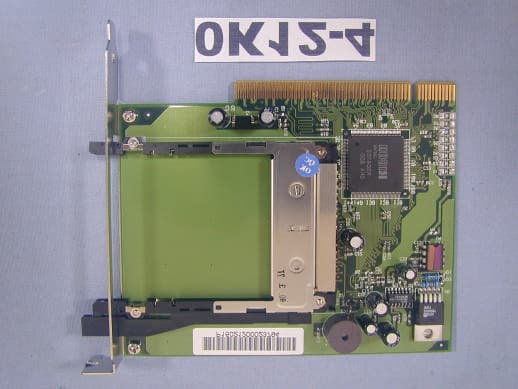
NKH9520
Jul 11, 2002Smart Wireless PCI Adapter 802
Equipment Class
JBP - Part 15 Class B Computing Device Peripheral
NKH9531
Jul 08, 2002Smart Wireless PCMCIA Adapter 802.11b
Equipment Class
DTS - Digital Transmission System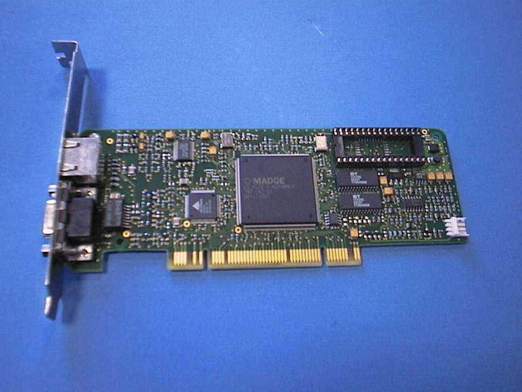
NKHPCI5
Sep 12, 2000Smart 100/16/4 PCI Ringnode
Equipment Class
JBP - Part 15 Class B Computing Device Peripheral