NKH9520Smart Wireless PCI Adapter 802
Madge Ltd.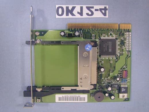
Click to zoom
Application Details
- Equipment Class
- JBP - Part 15 Class B Computing Device Peripheral
- Date of Grant
- Jul 11, 2002
- Application Purpose
- Original Equipment
- Date of Application
- Jul 11, 2002
- Equipment Note
- Smart Wireless PCI Adapter 802
- Company
- Madge Ltd.
- Country
- United Kingdom
Documents & Files
Document Text
Text extracted from the exhibit documents filed with the FCC. Open a document above to read the original.
Users Manual
User's Guide [ [ 95-20 All trademarks, service marks, trade names, and copyrights are properties of their respective owners. PC Card Drive series are high-performance PCI-to-PC Card adapters that support one PC Card socket, compliant with 16-bit PC Card Standard defined in 1997 PC Card Standard. 95-20 is also compliant with 32-bit CardBus Standard. PC Card Drive series provide rich features that make them the best choice for bridging between PCI and PC Card in desktop computers. Unique software configurable interrupt routing circuit and necessary driver software is provided together for PC Card Drive series to serve IO cards requiring IRQ functionality from the socket; enables PC Card Drive support almost all of the PC Card applications including: SRAM card, Linear Flash card, ATA card, Modem card, and Wireless LAN card. The 95-20 is compliant with the 16-bit PC Card specification defined in PCMCIA Release 2.1/JEIDA 4.1 and 32-bit CardBus ;can supports any 8-bit/16-bit/32-bit PC Card in one socket, powered at 3.3V/5.0V as required. Introduction Features of 95-20 * Supports 16-bit(PCMCIA 2.1/JEIDA 4.1) and 32-bit(CardBus) PC Card. * One rear access PC Card slot. *PCI Local Bus Specification Revision 2.1 compliant. *PC Card Standard 95/97 compliant. *3.3V / 5.0V operation. *Intel 82365SL register compatible, ExCA compatible. *Supports IRQ steering, software driver provided. *Ideal for data transfer or backup between desktop PC and mobile computer. The 95-20 provides one rear PC Card socket which is capable of accepting Type I/Type II/Type III PC Card. Introduction PC Card Socket PC Card Ejector Package Contents 95-20 contains: * 95-20 PCI Adapter x1 *User's Guidex1 *Setup Diskettex1 If there are any shortages, please contact your local dealer. System Requirements To install and use the PC Card Drive series, your system must meets following requirements. Hardware Requirements *IBM PC Compatible Computer *Free PCI Expansion Slot Software Requirements *Microsoft Windows 98 *Microsoft Windows 98SE *Microsoft Windows ME *Microsoft Windows 2000 *Microsoft Windows XP Software Setup The device driver software contained in the Setup Diskette is necessary for appropriate operation of the PC Card Drive series. Together with the special IRQ steering circuit embedded in the chip set, the driver software accomplishes necessary hardware configuration and IRQ routing emulation for the PC Card Drive. Included in the Setup Diskette are software drivers for various operating systems including Windows 98/98SE/ME/2000. Setup PC Card Drive series in Windows XP requires no software setup. For all the other supported system, software setup should be performed first, then the hardware setup. A setup program is provided to automatically identify the running system and install corresponding software driver accordingly. Please refer to following instructions to install the device driver software for your PC Card Drive series. Software Setup * If your system is Windows XP, you can skip this chapter. Software Setup Procedure 1. Power on your computer with Windows 98/98SE/ME/ 2000. 2. Insert the Setup Diskette into the floppy disk drive of your computer. 3. Click on the Start button on the task bar to open the Start menu. 4. Click on Run, the Run dialog box appears. 5. In the text box, type in A:\Setup.exe (where A: is the floppy disk drive letter) to execute the setup program. 6. The welcome dialog box appears, click Next> to continue setup. 7. The Software License Agreement dialog box appears. Read through the Software License Agreement, and then click Yes to continue setup. 8. The setup program will automatically identify the running system, install corresponding software, and configure your system for the PC Card Drive series. Following the completion of software driver setup, the Setup Complete dialog box appears. 9. Click Finish to complete the software setup. Hardware Setup After software setup, please refer to following instructions to install your PC Card Drive hardware. 1. Before trying to install your PC Card Drive, please power off your computer and remove the power plug from the wall outlet. 2. Disassemble and remove the cover of your computer. For instructions on removing the cover of your computer, refer to the manual provided with your computer. 3. nstall the PCI adapter into the slot and utilize the mounting screw to secure the PCI adapter in place. Locate a free PCI slot, i 4. Re-place and secure the cover of your computer. 5. Re-connect the power plug back to the wall outlet and power on your computer. Hardware setup completes. Specification Specification of 95-20: oo oo *PCI Local Bus Specification Revision 2.1 compliant. *PCMCIA 2.1, JEIDA 4.1, and CardBus compliant. *3.3V/5.0V operation. *Intel 82365SL register compatible, ExCA compatible. *ATA disk interface support. *Supports Hot-Swapping. Insert and remove PC Card without shutting down system. *Power saving suspend mode support. * Ambient temperature under bias 0 C to 70 C * Storage temperature -65 C to 150 C * PCI-to-PCMCIA host bridge R5C475 II * Max. Power Supply on sockets VCC at 3.3V for 1A VCC at 5.0V for 1A Troubleshooting 1.If your computer is COMPAQ DeskPro EN series, you may encounter following problem: System freezes while booting up after installing PC Card Drive in the computer. Solution: Before installing, please go to Http://www.compaq.com/ to download the latest version of ROMPaq ROM Image(V2.11 or later); then follow the instructions COMPAQ provides to update the system BIOS. You can install the software and hardware of PC Card Drive without problems after BIOS update. 2. If you have any further questions, please contact your local dealer. If you have problem with inserting PC Card into the socket, please do not push and enforce the card into the socket, because it may cause unexpected damage to the card or PC Card Drive. At this condition, turn the card over and try again. User's Guide for 95-20(3.3V/5V) Federal Communications …
Text truncated - open the document above for the full version.
External Photos
- EUT
ID Label/Location Info
FCC ID LABLE Sample of FCC ID Label FCC ID : NKH9520 THIS DEVICE COMPLIES WITH PART 15 OF THE FCC RULES. OPERATION IS SUBJECT TO THE FOLLOWING TWO CONDITIONS. (1) THIS DEVICE MAY NOT CAUSE HARMFUL INTERFERENCE AND (2) THIS DEVICE MUST ACCEPT ANY INTERFERENCE RECEIVED, INCLUDING INTERFERENCE THAT CAUSE UNDESIRED OPERATION.
Internal Photos
EUT - PC inside
Test Report
Spectrum Research & Testing Lab., Inc. No. 101-10, Ling 8, Shan-Tong Li, Chung-Li City, Taouyan, Taiwan, R.O.C. TEST REPORT Reference No.:A02061306 Report No.:FCBA02061306 Page:1 of 14 Date:June 18, 2002 FCC ID:NKH9520 Lab Code: 200099-0 Spectrum Research & Testing Lab., Inc. No. 101-10, Ling 8, Shan-Tong Li, Chung-Li City, Taouyan, Taiwan TEST REPORT Reference No.:A02061306 Report No.:FCBA02061306 Page:2 of 14 Date:June 18, 2002 FCC ID:NKH9520 Table of Contents 1. DOCUMENT POLICY AND TEST STATEMENT......................................................3 1.1 DOCUMENT POLICY....................................................................................................3 1.2 TEST STATEMENT........................................................................................................3 2. DESCRIPTION OF EUT AND TEST MODE.............................................................4 2.1 GENERAL DESCRIPTION OF EUT............................................................................4 2.2 DESCRIPTION OF EUT INTERNAL DEVICE...........................................................4 2.3 DESCRIPTION OF TEST MODE.................................................................................4 2.4 DESCRIPTION OF SUPPORT UNIT..........................................................................5 3. DESCRIPTION OF APPLIED STANDARDS.............................................................6 4. CONDUCTED EMISSION TEST.................................................................................6 4.1 CONDUCTED EMISSION LIMIT.................................................................................6 4.2 TEST EQUIPMENT........................................................................................................6 4.3 TEST SETUP..................................................................................................................7 4.4 TEST PROCEDURE......................................................................................................7 4.5 EUT OPERATING CONDITION...................................................................................7 4.6 TEST RESULT................................................................................................................8 5. RADIATED EMISSION TEST......................................................................................9 5.1 RADIATED EMISSION LIMIT.......................................................................................9 5.2 TEST EQUIPMENT.....................................................................................................10 5.3 TEST SET-UP...............................................................................................................11 5.4 TEST PROCEDURE...................................................................................................12 5.5 EUT OPERATING CONDITION................................................................................12 5.6 RADIATED EMISSION TEST RESULT...................................................................13 6. TERMS OF ABRIVATION...........................................................................................14 Spectrum Research & Testing Lab., Inc. No. 101-10, Ling 8, Shan-Tong Li, Chung-Li City, Taouyan, Taiwan TEST REPORT Reference No.:A02061306 Report No.:FCBA02061306 Page:3 of 14 Date:June 18, 2002 FCC ID:NKH9520 1. DOCUMENT POLICY AND TEST STATEMENT 1.1 DOCUMENT POLICY - The report shall not be reproduced except in full, without the written approval of SRT Lab, Inc. - The report must not be used by the applicant to claim that the product is endorsed by NVLAP. - The NVLAP logo applies only to the applicable standards specified in this report. 1.2 TEST STATEMENT - The test results in the report apply only to the unit tested by SRT Lab. - There was no deviation from the requirements of test standards during the test. - AC power source, 120 Vac/60 Hz, was used during the test. Spectrum Research & Testing Lab., Inc. No. 101-10, Ling 8, Shan-Tong Li, Chung-Li City, Taouyan, Taiwan TEST REPORT Reference No.:A02061306 Report No.:FCBA02061306 Page:4 of 14 Date:June 18, 2002 FCC ID:NKH9520 2. DESCRIPTION OF EUT AND TEST MODE 2.1 GENERAL DESCRIPTION OF EUT PRODUCT Smart Wireless PCI Adapter 802.11b MODEL NO. 95-20 POWER SUPPLY DC 5V from PC CABLE N/A NOTE: The EUT is a high-performance PCI-to-PC Card Adapter that supports one PC card socket complied with the 16-bit PC Card and 32-bit CardBus Card standard which is defined in 1997 PC Card Standard. 2.2 DESCRIPTION OF EUT INTERNAL DEVICE DEVICE BRAND / MAKER MODEL # REMARK N/A 2.3 DESCRIPTION OF TEST MODE The worst emission was EUT full load and transmitter data to PC. Spectrum Research & Testing Lab., Inc. No. 101-10, Ling 8, Shan-Tong Li, Chung-Li City, Taouyan, Taiwan TEST REPORT Reference No.:A02061306 Report No.:FCBA02061306 Page:5 of 14 Date:June 18, 2002 FCC ID:NKH9520 2.4 DESCRIPTION OF SUPPORT UNIT The EUT was configured by the requirement of ANSI C63.4 and CISPR 22. All interface ports were connected to the appropriate support units via specific cables. The support units and cables are listed below. NO DEVICE BRAND MODEL # FCC ID / DOC CABLE 1 PRINTER EPSON STYLUS C20SX DOC 1.5m unshielded power cord 1.2m shielded data cable(S2) 2 MODEM DATATRONICS 1200CK E2050V1200CK 1.5m unshielded power cord 1.2m shielded data cable(S2) 3 MONITOR SUNSUNG PG17IS DOC 1.8m unshielded power cord 1.2m shielded data cable(S2) 4 KEYBOARD ACER 6311-TA DOC 1.2m unshielded data cable 5 MOUSE HP M-S34 LZA7068626 1.2m unshielded data cable 6 PC MSI MS-6165 DOC 1.8m unshielded power cord NOTE 1. For the actual test configuration, please refer to the photos of testing. 2. Cable - S1Single point shielding. S2360shielding. S3Double point shielding Spectrum Research & Testing Lab., Inc. No. 101-10, Ling 8, Shan-Tong Li, Chung-Li City, Taouyan, Taiwan TEST REPORT Reference No.:A02061306 Report No.:FCBA02061306 Page:6 of 14 Date:June 18, 2002 F…
Text truncated - open the document above for the full version.
Test Setup Photos
- Conducted test - Radiated test
Contact Information
Applicant
Bob Lindsey(VP Operations, R&D)
Test Firm
Spectrum Research & Testing Lab.Linda Chiang
Technical Specifications
| # | Rule Parts | Frequency Range | Power Output |
|---|---|---|---|
| 1 | 15B | - | - |
Other Applications from Madge Ltd.
NKH9610
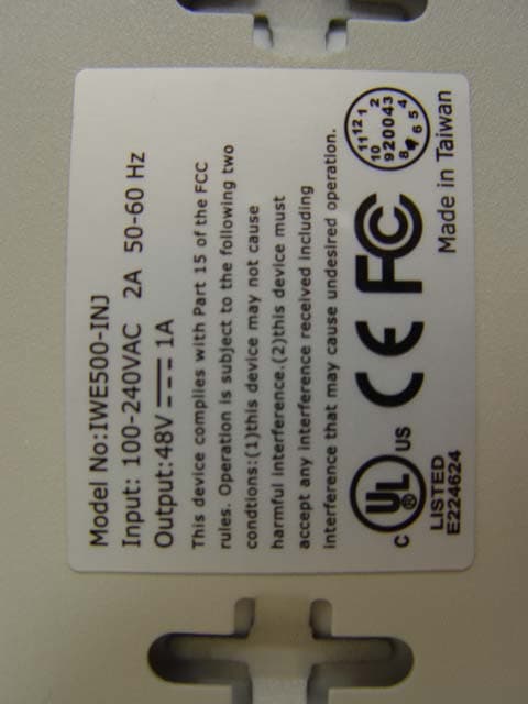
Dec 13, 2004Enterprise Access Point 802.11b/g Dual-Radio
Equipment Class
DTS - Digital Transmission System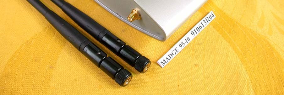
NKH9510
Jul 17, 2002Smart Wireless Access Point 802.11b
Equipment Class
DTS - Digital Transmission System
NKH9531
Jul 08, 2002Smart Wireless PCMCIA Adapter 802.11b
Equipment Class
DTS - Digital Transmission System
NKHPCI5
Sep 12, 2000Smart 100/16/4 PCI Ringnode
Equipment Class
JBP - Part 15 Class B Computing Device Peripheral
NKHPCI4
Oct 12, 1999Smart 100/16/4 PCI-HS Ringnode Mk2
Equipment Class
JBP - Part 15 Class B Computing Device Peripheral