NWJ10A001ADual Mode - Duasl Band Cellular Telephone
Panasonic Mobile Communications Development Corporation of USA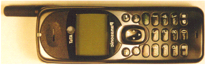
Click to zoom
Application Details
- Equipment Class
- TNB - Licensed Non-Broadcast Station Transmitter
- Date of Grant
- Mar 23, 2000
- Application Purpose
- Original Equipment
- Date of Application
- Jun 27, 1999
- Equipment Note
- Dual Mode - Duasl Band Cellular Telephone
- Frequency Range
- 1850.04000000 - 1909.95000000
- Country
- United States
Documents & Files
Document Text
Text extracted from the exhibit documents filed with the FCC. Open a document above to read the original.
Cover Letter(s)
Panasonic Matsushita Mobile Communications Development Corporation of U.S.A. FCC ID: NWJ10A001A COVER LETTERS Page 1 of 4 1225 Northbrook Parkway • Suite 2-400 • Suwanee, GA 30024 • Phone (770)338-6000 • Fax (770)338-6210 MATSUSHITA MOBILE COMMUNICATIONS DEVELOPMENT CORPORATION OF U.S.A. Application for Type Acceptance Panasonic Handheld Portable Cellular Telephone FCC ID: NWJ10A001A THIS COVER PAGE IS FOR FILING IDENTIFICATION ONLY Panasonic Matsushita Mobile Communications Development Corporation of U.S.A. FCC ID: NWJ10A001A COVER LETTERS Page 2 of 4 1225 Northbrook Parkway • Suite 2-400 • Suwanee, GA 30024 • Phone (770)338-6000 • Fax (770)338-6210 Date: 6/28/1999 Authorization & Evaluation Division. Federal Communications Commission Laboratory. 7435 Oakland Mills Road. Columbia, MD 21045. Subject: Application for Type Acceptance of Transmitter with FCC ID: NWJ10A001A Gentlemen: Matsushita Mobile Communications Development Corporation of U.S.A. in Suwanee, Ga., herein submits application for type acceptance of the subject transmitter. This transmitter is intended for use in a dual mode – dual band cellular telephone application with capabilities for clear communications with a maximum transmit power of 600 mWatt or 27.8 dBm (Variable Power) down to as low as 0.16 mWatts in PCS mode. The subject transmitter complies with Section 90.203 of the rules in that the operator cannot directly program transmit frequencies using only the unit's normally accessible external controls. Enclosed is a complete Type Acceptance Application. Contact me (770) 338-6270 if you require any additional information. Best Regards, Pieter C. Seidel Senior System Test Engineer 770-338-6210 Fax Number Panasonic Matsushita Mobile Communications Development Corporation of U.S.A. FCC ID: NWJ10A001A COVER LETTERS Page 3 of 4 1225 Northbrook Parkway • Suite 2-400 • Suwanee, GA 30024 • Phone (770)338-6000 • Fax (770)338-6210 Date: 6/28/99 Authorization & Evaluation Division. Federal Communications Commission Laboratory. 7435 Oakland Mills Road. Columbia, MD 21045. Subject: REQUEST FOR CONFIDENTIALITY Pursuant to sections 0.457 (d) (1) (ii) and 0.459 of the commission’s rules, the applicant hereby requests confidential treatment of some of the information accompanying this application for FCC ID: NWJ10A001A as outlined below: • Block Diagram • Schematics • Theory of operation and circuit descriptions • Users Manual This information contains trade secrets and proprietary information not customarily released to the public. The public disclosure of this information might be harmful to the applicant and provide unjust benefits to its competitors. The applicant understands that pursuant to rule 0.457d, disclosure of this application and all accompanying documentation will not be made before the date of the grant for this application. MMCD Panasonic Pieter C. Seidel Senior System Test Engineer Panasonic Matsushita Mobile Communications Development Corporation of U.S.A. FCC ID: NWJ10A001A COVER LETTERS Page 4 of 4 1225 Northbrook Parkway • Suite 2-400 • Suwanee, GA 30024 • Phone (770)338-6000 • Fax (770)338-6210 LIST OF EXHIBITS DESCRIPTION FCC REFERENCE Cover Letters 1. Cover 2. Letter of Intent 3. Confidentiality statement 4. List of Exhibits I. Attestation Statement2.983(a) II. Identification label information2.983-(f) III. Block Diagrams2.983(d7) IV. Operational Description 1. General Information2.983-(a,b,c) 1. Production Plans2.981-(c) 2. Application References2.1061 2. Technical Characteristics2.983-(d1,2,3,4,5) 3. Function of Active devices2.983-(d6) 4. Circuit Description 1. Frequency Stabilizing2.983-(d10) 3.Harmonic Suppression2.983-(d11) 2. Modulation Limiting2.983-(d11) 4.Power Limiting2.983-(d11) 5.Attenuating Higher Audio Freq.2.983-(d11) 6.Digital Modulation Techniques2.983-(d12) 7.ESN Protection22.919 V. Schematics2.983-(d7) VI. Tune Procedure / Parts Lists2.983-(d9) VII. Test Report2.983-(e) 1.Data Index 2.RF Output-Data2.985 3.Modulation Characteristics2.987, 22.915 A. Audio Response 2.987(a) B. Low Pass Filter Response2.987(a) C. Modulation Limiting2.987(b) 4. Occupied Bandwidth2.989, 22.917 5. Conducted Spurious Emissions 2.991, 24.238, 22.917(e,f) 6. Radiated Spurious Emissions2.993, 24.238, 22.917(e,f) 7. Frequency Stability (Temp & Supply Volt)2.995 8. Radiated Power22.913, 24.232(b) VIII. RF Exposure - SAR2.1093 IX. Internal Photograph(s)2.983-(g) X. External Photograph(s)2.983-(g) XI. User Manual2.983-(d8) XII. Test System and Measurement Procedure2.999 & 2.947
External Photos
Panasonic Matsushita Mobile Communications Development Corporation of U.S.A. FCC ID: NWJ10A001A EXTERNAL PHOTOGRAPHS Page 1 of 4 1225 Northbrook Parkway • Suite 2-400 • Suwanee, GA 30024 • Phone (770) 338-6000 • Fax (770) 338-6210 EXTERNAL PHOTOGRAPHS The following photographs are attached. • Front View. • Back Side with Battery View. • Back Side no Battery View (FCC Label location). • Top View. • Bottom View of Connector. • Antenna Side View. • Accessory Jack Side View. Front View. Panasonic Matsushita Mobile Communications Development Corporation of U.S.A. FCC ID: NWJ10A001A EXTERNAL PHOTOGRAPHS Page 2 of 4 1225 Northbrook Parkway • Suite 2-400 • Suwanee, GA 30024 • Phone (770) 338-6000 • Fax (770) 338-6210 Back Side with Battery View. Back Side no Battery View (FCC Label location). Panasonic Matsushita Mobile Communications Development Corporation of U.S.A. FCC ID: NWJ10A001A EXTERNAL PHOTOGRAPHS Page 3 of 4 1225 Northbrook Parkway • Suite 2-400 • Suwanee, GA 30024 • Phone (770) 338-6000 • Fax (770) 338-6210 Top View. Bottom View of Connector. Panasonic Matsushita Mobile Communications Development Corporation of U.S.A. FCC ID: NWJ10A001A EXTERNAL PHOTOGRAPHS Page 4 of 4 1225 Northbrook Parkway • Suite 2-400 • Suwanee, GA 30024 • Phone (770) 338-6000 • Fax (770) 338-6210 Accessory Jack Side View. Antenna Side View.
ID Label/Location Info
Panasonic Matsushita Mobile Communications Development Corporation of U.S.A. FCC ID: NWJ10A001A IDENTIFICATION LABEL Page 1 of 4 1225 Northbrook Parkway • Suite 2-400 • Suwanee, GA 30024 • Phone (770) 338-6000 • Fax (770) 338-6210 IDENTIFICATION LABEL -- Pursuant 2.983 (f) The label is a paper polyester film laminate with a pressure sensitive adhesive backing. The adhesive is a permanent type. Model Numbers EB-TX110A - AT&T Business Model EB-TX120A - AT&T Durable Model EB-TX110F - Affiliate Carrier Business Model EB-TX120F - Affiliate Carrier Durable Model EB-TX110C - Canada Business Model EB-TX120C - Canada Durable Model Panasonic Matsushita Mobile Communications Development Corporation of U.S.A. FCC ID: NWJ10A001A IDENTIFICATION LABEL Page 2 of 4 1225 Northbrook Parkway • Suite 2-400 • Suwanee, GA 30024 • Phone (770) 338-6000 • Fax (770) 338-6210 Location of label on the back of the housing. Label Print.
Internal Photos
Panasonic Matsushita Mobile Communications Development Corporation of U.S.A. FCC ID: NWJ10A001A INTERNAL PHOTOGRAPHSPage 1 of 5 1225 Northbrook Parkway • Suite 2-400 • Suwanee, GA 30024 • Phone (770)338-6000 • Fax (770)338-6210 INTERNAL PHOTOGRAPHS • Internal front view showing PCB with shield and mating Front Cover. • Internal back view showing PCB with shield and mating Back Cover. • Front Side PCB with shield removed. • Back Side PCB with shield removed. Internal front view showing PCB with shield and mating Front Cover. Panasonic Matsushita Mobile Communications Development Corporation of U.S.A. FCC ID: NWJ10A001A INTERNAL PHOTOGRAPHSPage 2 of 5 1225 Northbrook Parkway • Suite 2-400 • Suwanee, GA 30024 • Phone (770)338-6000 • Fax (770)338-6210 Internal back view showing PCB with shield and mating Back Cover. Panasonic Matsushita Mobile Communications Development Corporation of U.S.A. FCC ID: NWJ10A001A INTERNAL PHOTOGRAPHSPage 3 of 5 1225 Northbrook Parkway • Suite 2-400 • Suwanee, GA 30024 • Phone (770)338-6000 • Fax (770)338-6210 Front Side PCB with shield removed. Panasonic Matsushita Mobile Communications Development Corporation of U.S.A. FCC ID: NWJ10A001A INTERNAL PHOTOGRAPHSPage 4 of 5 1225 Northbrook Parkway • Suite 2-400 • Suwanee, GA 30024 • Phone (770)338-6000 • Fax (770)338-6210 Back Side PCB with shield removed.
Parts List/Tune Up Info
Panasonic Matsushita Mobile Communications Development Corporation of U.S.A. FCC ID: NWJ10A001A TUNE INFORMATIONPage 1 of 25 1225 Northbrook Parkway • Suite 2-400 • Suwanee, GA 30024 • Phone (770) 338-6000 • Fax (770) 338-6210 1. EV Specification / Tune Procedure This specification contains only the information required for electronic adjustment of the TEMPEST handset. The specification contains two sections; the adjustment procedure, and the adjustment range and configuration matrix. Adjustment Procedure – Gives a detailed description of each adjustment of the handset in the required sequence. Adjustment Range and Configuration Matrix – Gives the adjustment parameter, adjustment limits, and default EV value, and brief equipment set up for each adjustment. 1.1. Electronic Adjustment Support – Overview TEMPEST will support electronic adjustment of various audio and RF related parameters through an external test set by putting the radio into adjust mode. This document covers the adjustment procedure using the external test set. All adjustments are typically done using channel 350 in the cellular band or channel 1000 in the PCS band unless otherwise specified with the transceiver and audio control set as required for the adjustment. The TEMPEST electronic adjustment allows for the setting of the following parameters: • AFC Tuning • RF RX DC Calibration • RF TX DC Calibration • Power Level • Compressor Reference Level • Standard Deviation • SAT Deviation • WBD / ST Deviation • DTMF Deviation • Discriminator Tuning • Expander Reference Level • RX Audio Level • RSSI Calibration • Battery Reference Voltage Calibration 1.2. Test Set Adjustment Operation The test set originated adjustments generally operate as follows: 1. Commands are sent as 9600 baud asynchronous serial data with 8 data bits, even parity. Commands are received on the RX data line and responses are sent on the TX data line. All commands are sent through the serial bus in the following format (in hex): 00 80 NN CC (D1) (D2) (D3) ... (Dn) where NN is the number of bytes sent (command plus data), CC is the command op code, and D1 through Dn are data associated with the command (see individual command below for number of data bytes expected). 2. The adjust mode is entered by first sending the Test Mode and then sending the Adjust Mode command. Panasonic Matsushita Mobile Communications Development Corporation of U.S.A. FCC ID: NWJ10A001A TUNE INFORMATIONPage 2 of 25 1225 Northbrook Parkway • Suite 2-400 • Suwanee, GA 30024 • Phone (770) 338-6000 • Fax (770) 338-6210 3. A set adjustment command (such as Set SAT) is sent to set up the hardware for the specified test with the current adjustment. 4. The Set Current Adjustment Value command is issued along with a value which is used to set the selected adjustment and update the hardware. This may be repeated as necessary until the final adjustment value is determined. 5. The Exit Adjustment Mode command is issued to exit adjustment mode with the option to save all adjustments to nonvolatile memory. Handset returns to test mode. 6. The Exit Active Adjustment Mode command is issued to exit the current adjustment with the option to save to active memory. Handset is still in adjustment mode. 7. When all adjustments are complete, the Normal Mode command can be sent to return the unit to normal operation. 8. ALL RF POWERS LISTED ARE NOT CORRECTED FOR THE INTERNAL TRANSMISSION LINE PATH LOSS. ADD 1.2 dB TO ALL RF POWERS IN THE CELLULAR BAND AND 2.2 dB TO ALL RF POWERS IN THE PCS BAND TO COMPENSATE FOR THE INTERNAL TRANSMISSION LINE PATH LOSS. 9. Adjustments must be performed at +25 ±5 °C in the order specified. Adjustments performed outside the temperature range may produce erroneous results. 10.The following two groups of adjustments are to be done in the order listed: Adjustments performed out of this order may produce erroneous results. Group A: Compressor Reference Level, then Standard Deviation, and then SAT, WBD, and DTMF Deviation Group B: Discriminator Tuning, then Expander Reference Level, and then RX Audio Level Panasonic Matsushita Mobile Communications Development Corporation of U.S.A. FCC ID: NWJ10A001A TUNE INFORMATIONPage 3 of 25 1225 Northbrook Parkway • Suite 2-400 • Suwanee, GA 30024 • Phone (770) 338-6000 • Fax (770) 338-6210 1.3. Enter Adjust Mode Use this command to put the unit under test (UUT) into adjust mode. This must be done before issuing any other adjust commands. 1.Apply DC power (7.0 VDC) to DC-PWR-IN at the I/O connector of the UUT. 2.Send Enter Test Mode command and then send Adjust Mode command. 1.4. Adjust AFC Tuning Voltage This procedure adjusts the AFC center value and the AFC scale factor. 1. Send Adjust AFC Control command. 2. Adjust AFC center value to 1.4 volts. 3.Send Set Current Adjustment Value with data: 130 for center value and 46 for scale factor 4.Measure the frequency of the transmitter at the RF port of the I/O connector. 5.Adjust AFC center value to 1.5 volts. 6.Send Set Current Adjustment Value with data: 140 for center value and 46 for scale factor 7. Measure the frequency of the transmitter at the RF port of the I/O connector. 8. Calculate AFC scale factor as follows: TX AFC scale factor (Hz / bit) = [Frequency (1.5 volts) – Frequency (1.4 volts)] / 10 AFC scale factor = Integer [880500000/Ch frequency * TX AFC scale factor] 9.Check to insure the AFC scale factor is in the range of 16 to 64 Hz. If it is not in range, skip to step 12 and discard settings. 10.Calculate AFC center value as follows: AFC center value = 130 + [Ch frequency – Frequency (1.4 volts)] / [TX AFC scale factor] 11.Send Set Current Adjustment Value with data: AFC center value (0 to 255), AFC scale factor (16 to 64) 12.Send Exit Active Adjustment Mode command with data: Save (1). 1.5. RF RX I/Q DC Calibration This procedure calibrates the A/D converters of the RX I and Q channels in the IFIC including the RF and demodulator circuits. 1.Apply –50 dBm, π/4 shifted DQPSK sig…
Text truncated - open the document above for the full version.
RF Exposure Info
* Consulting * Research * Training * Certification Testing Since 1981 51 Spectrum Waytel: (613) 820-2730 Nepean, Ontariovisit our Web Pages: www.aprel.comfax: (613) 820-4161 Canada K2R 1E6email: [email protected] 02 July, 1999 Federal Communications Commission Office of Engineering &Technology 1919 M Street, N.W., Room 852 Washington, DC 20554 Re:Submitting Attachments for TDMA Phone FCC ID: NWJ10A001A and Confirmation #: EA94679 To Whom It May Concern: The accompanying SAR documents are additions to the basic submission. The Panasonic TDMA phone operates in dual modes (AMPS and TDMA) and dual bands (835 MHz and 1900 MHz). In addition the phone can be used in two manners: 1. Against the side of the head as a regular handset 2. In a case with a belt clip intended to be attached to the belt and a headset for hands-free operation The handset was tested in the regular hand-held position against the head in all three modes of operation (835MHz AMPS, 835MHz TDMA and 1900MHz TDMA). The maximum 1g SAR for each of these modes was found to be: 1. 835MHz AMPS1.436 W/kg 2. 835MHz TDMA0.577 W/kg (estimated from 1. above and the ratio of peak local SARs in section 6.2.4 of the Project #: MATB-EBTX110A-3252B report) 3. 1900 TDMA1.241 W/kg The worst of these (835 AMPS) was then explored with muscle tissue to simulate the body worn hands-free mode. Both sides of the handset at high, middle and low frequencies were checked and the worst of these six was parametrically investigated as a function of separation between the handset and the phantom. A 1g SAR of 1.5 W/kg was determined to occur at 11mm from the body. Since the manufacturer supplied case and belt clip puts the handset 25mm from the body, this configuration also passes the FCC 96-326 requirement. The documents added are (all in PDF format): 1. FINAL SAR report for PANASONIC BRAIN.pdf (Project #: MATB-EBTX110A-3252B) 2. FINAL SAR report for PANASONIC BODY.pdf (Project #: MATB-EBTX110A-3252M) 3. 31-SSI_DRB_TP_D01_031Ver5.PDF (Phantom Design Requirements) 4. 32-SSI_DRB_TP_D01_032Rev4.PDF (Probe Design and Calibration Requirements) * Consulting * Research * Training * Certification Testing Since 1981 51 Spectrum Waytel: (613) 820-2730 Nepean, Ontariovisit our Web Pages: www.aprel.comfax: (613) 820-4161 Canada K2R 1E6email: [email protected] 5. 33-SSI_DRB_TP_D01_033Ver4.PDF (Tissue Recipe and Calibration Requirements) 6. 34-SSI_DRB_TP_D01_034Ver2.PDF (Positioning and Scanning Requirements) If you have problems opening any of these documents please contact Dr. Paul G. Cardinal as soon as possible to rectify the situation. Dr. Cardinal can be reached at: [email protected] Tel: (613) 820-2730 Fax: (613) 820-4161 Regards, Paul G. Cardinal, Ph.D. Director, Laboratory Operations Certification Report on Specific Absorption Rate (SAR) Experimental Analysis Panasonic Matsushita Mobile Communications Development Corporation of U.S.A Dual-Mode Dual Band TDMA Phone (EB-TX110A) Date: 29 June, 1999 51 Spectrum Way Nepean ON K2R 1E6 Tel: (613) 820-2730 Fax: (613) 820-4161 email: [email protected] This report shall not be reproduced, except in full, without the express written approval of APREL Laboratories. Page 1 of 25© APREL Project #: MATB-EBTX110A-3252B 51 Spectrum WayTel. (613) 820-2730 Nepean, Ontario, K2R 1E6Fax (613) 820 4161 e-mail: [email protected] CERTIFICATION REPORT Subject:Specific Absorption Rate (SAR) Experimental Analysis Product:Dual-Mode Dual-Band TDMA Phone Model:EB-TX110A Client:Panasonic Matsushita Mobile Communications Development Corporation of U.S.A. Address:1225 Northbrook Pkwy. Suite 2-400 Suwanee, GA. 30024 U.S.A. Project #:MATB-EBTX110A-3252B Prepared by:APREL Laboratories 51 Spectrum Way Nepean, Ontario K2R 1E6 Tested by___________________________Date: _________________ Antonio Utano, B.A.Sc. (EE) Submitted by___________________________Date: _________________ Dr. Paul G. Cardinal Director, Laboratories Approved by___________________________Date: _________________ Dr. Jacek J. Wojcik, P. Eng. Page 2 of 25© APREL Project #: MATB-EBTX110A-3252B 51 Spectrum WayTel. (613) 820-2730 Nepean, Ontario, K2R 1E6Fax (613) 820 4161 e-mail: [email protected] FCC ID:NWJ10A001A Applicant:Panasonic Matsushita Mobile Communications Development Corporation of U.S.A. Equipment:Dual-Mode Dual-Band TDMA Phone Model:EB-TX110A Standard:FCC 96 –326, Guidelines for Evaluating the Environmental Effects of Radio-Frequency Radiation ENGINEERING SUMMARY This report contains the results of the engineering evaluation performed on a dual-mode dual-band TDMA phone (835 MHz AMPS, 835 MHz TDMA and 1900 MHz TDMA). The measurements were carried out in accordance with FCC 96-326. The dual-mode dual-band TDMA phone was evaluated for its maximum power level in each mode and band. The phone was tested at high, middle, and low frequencies, for both bands, and both modes, with the maximum SAR coinciding with the peak performance RF output power of channel 991 (low, 824 MHz), in the AMPS mode. Test data and graphs are presented in this report. This unit as tested, and as it will be marketed and used is found to be compliant with the FCC 96-326 requirement, for an uncontrolled RF exposure environment. . Page 3 of 25© APREL Project #: MATB-EBTX110A-3252B 51 Spectrum WayTel. (613) 820-2730 Nepean, Ontario, K2R 1E6Fax (613) 820 4161 e-mail: [email protected] TABLE OF CONTENTS 1.Introduction....................................................................................................................4 2.Applicable Documents...................................................................................................4 3.Equipment Under Test...................................................................................................4 4.Test Equipment..............................................................................................................5 5.Test Methodology..........................................................................................................5 6.Te…
Text truncated - open the document above for the full version.
RF Exposure Info
Panasonic Matsushita Mobile Communications Development Corporation of U.S.A. 1225 Northbrook Parkway • Suite 2-400 • Suwanee, GA 30024 • Phone (770) 338-6000 • Fax (770) 338-6210 Mr. Errol Chang FCC Application Processing Branch November 22, 1999 FCC ID: NWJ10A001A Correspondence Reference Number: 10009 731 Confirmation Number EA94679 Date of Original E-Mail: 10/07/1999 Dear Mr. Chang: I am replying to your e-mail and I am forwarding to you responses from Aprel Labs for items 5-7 and 9-11. The relevant portions of the FCC’s e-mail follow with our responses inserted in the appropriate place. I will answer 1-4 and 8 and then attached to the bottom will be items 5-7 and 9-11. Seidel, Pieter From: [email protected] Sent: Thursday, October 07, 1999 11:38 AM To: [email protected] Subject: Information required To: Pieter Seidel, Panasonic - MMCD From: Errol Chang [email protected] FCC Application Processing Branch Re: FCC ID NWJ10A001A Applicant: Matsushita Mobile Communications Development Corporation of USA Correspondence Reference Number: 10009 731 Confirmation Number: EA94679 Date of Original E-Mail: 10/07/1999 1. The reported ERP for TDMA mode in the cellular band appears to be inconsistent with those in the SAR report and AMPS mode output. Maximum conducted output was measured (apparently by Panasonic) at around 315 mW for AMPS and TDMA modes in the cellular band. Report ERP by APREL has 330 mW ERP for AMPS mode and 520 mW ERP for TDMA. The conducted output measured during SAR tests for AMPS and TDMA are similar to those from Panasonic. The measured ERP value for TDMA mode (520 mW) in the cellular band needs to be confirmed. The maximum conducted output power measured by Panasonic at around 315 mW for AMPS and TDMA modes in the cellular band were reported wrong. The AMPS numbers were correct but the 800 TDMA numbers were wrong. The conducted output power measured by Aprel is below and they agree with the ERP numbers. Panasonic Matsushita Mobile Communications Development Corporation of U.S.A. 1225 Northbrook Parkway • Suite 2-400 • Suwanee, GA 30024 • Phone (770) 338-6000 • Fax (770) 338-6210 TDMA - 835 MHz 6.27 6.13 L991 5.95 5.56 M384 5.41 5.16 H798 2. The EAS or 731 form is requesting for 600 mW ERP for AMPS and TDMA output in the cellular band and 600 mW EIRP for PCS/TDMA. These are inconsistent with the measured output values in the test reports, please revise accordingly. I can request a change in form 731 but I cannot change the form 731 in the electronic filing format. I do not know what is appropriate to change it to anyway. Is this power number what the maximum the product will produce? It asks for rated in Watts that is conducted, so EIRP and ERP are radiated and do not apply. My competitors filing show 0.6 W and their phones do not put out but 0.4 W in AMPS. In digital modes the phone is tuned to just under 0.6 W and much lower in AMPS mode. The way I read 731, 0.6 is the correct number for the digital modes and AMPS is where the question lies. Can you please call me and answer this question? 3. The pictures in the device photo exhibit are different than that indicated in the SAR report. There appears to be different outer packaging or models for this phone. This phone also has 4 battery options, 2 each for standard and extended batteries. It needs to be clarified if any variations in battery performance due to these battery options could affect the SAR for the different operating conditions and configurations. If the outer dimensions of the different models for this phone could affect worst case SAR, it needs to be clarified. There are two models, business (EBTX-110) and durable (EBTX-120). The only difference is the durable has a rubber coating added to the business models plastic. This makes the durable slightly larger and thus providing more space between the user and the phone. SAR would then be decreased with this model in any position. SAR was taken with the worst case battery as noted in that report. Appendix A in the user manual has the dimensions. 4. The operator’s manual indicates the phone has an optional setting to allow an external antenna to be used for vehicle mount operations. In order to qualify for categorical exclusion from routine evaluation for MPE, a 20-cm separation distance is needed between persons and the antenna and the ERP must be 1.5 W or less. This exclusion is dependent on the antenna installation and antenna gain. Please clarify and include appropriate installation and operation requirements in the manual for users and installers. Panasonic Matsushita Mobile Communications Development Corporation of U.S.A. 1225 Northbrook Parkway • Suite 2-400 • Suwanee, GA 30024 • Phone (770) 338-6000 • Fax (770) 338-6210 On page 51 of the operator’s manual, the phone has an optional setting to allow the user to select an external antenna to be used for the handsfree cradle. This feature has been removed and the user cannot select the antenna. When the phone is in the handsfree cradle the external antenna is automatically selected. The operator’s manual has been revised since the original filing. As for installation, we do not sell an antenna with our kit. The antenna selection is left up to the installer. 8. This phone (and/or different models) allows body-worn operations using two Panasonic provided holsters. A minimum separation distance of 1.1 cm was determined and one of the holsters was also tested with a phone. Please clarify both holsters will provide at least the required separation distance for meeting SAR limit with respect to the different battery options and also clarify if there are any metallic parts or components in the belt-clips or other parts of the holsters that could affect SAR. The belt clip provides 24 mm of separation from the body. This measurement was taken from the outside edge of the clip (that would touch the body) and the inside side of the case touching the back of the radio. The clip does have a bent spring steel…
Text truncated - open the document above for the full version.
RF Exposure Info
Panasonic Matsushita Mobile Communications Development Corporation of U.S.A. Pieter C. Seidel Sr. System Test Engineer - Direct Phone. 770.338.6270 1225 Northbrook Parkway • Suite 2-400 • Suwanee, GA 30024 • Phone (770) 338-6000 • Fax (770) 338-6210 This is in response to : Correspondence Reference Number: 11037 731 Confirmation Number:EA94679 Date of Original E-Mail:12/15/1999 > 2. You may upload a scanned copy of your revised 731 form to cover > letter exhibits or to clearly state the changes through a cover > letter upload to correct output power. Note: output power indicated > on the grant are ERP for Part 22 operations and EIRP for Part 24 > operations, as required or established in those rule sections. A > phone with 400 mW conducted output listing for 600 mW ERP is not > unreasonable, since it can all depend on the antenna gain and design > or the particular phone. What is listed on the grant should be based > on actual ERP or EIRP measurement data. If a device has an external > detachable antenna, conducted output may be listed. > Please revise the 731 form accordingly with respect to the actual > radiated measurements. Note: ERP and/or EIRP are generally indicated ! as grant comments since a year or so ago. I can find no way to copy my 731 or create a new one. Bette Taube has told me that I must Email her with any changes. Included in the correspondence with this attachment I have asked for the 731 to reflect 0.35 W ERP for AMPS, 0.6 W ERP fro TDMA mode, and 0.8 W EIRP for the PCS modes. > 4. Response #4 did not fully address the original question. Please > review previous correspondence and address issues, including > qualification for categorical exclusion, 20 cm or more installation > and operating requirement, antenna gain issues etc. If this device > allows operating configurations using external antennas, the > operating and installation requirements for such operations must be > addressed and specified to users and installers to satisfy MPE > requirements. Leaving it up to the installers but without telling > them how to comply with MPE requirements is not acceptable. At a > minimum, the antenna gain and installation configurations that > qualify this device for categorical exclusion (see 2.1091) and/or MPE > compliance should be determined and given to users and installers to > satisfy compliance. The purpose of such requirements should also be ! stated - for purpose of FCC RF exposure compliance. The phone originally had a car kit that the choice of antenna was left upto the installer. When I further investigated this I found that the car kit had been cancelled and not removed from the manual. For future products that have car kits we will have an instalation manual and a recommeneded antenna. Panasonic Matsushita Mobile Communications Development Corporation of U.S.A. Pieter C. Seidel Sr. System Test Engineer - Direct Phone. 770.338.6270 1225 Northbrook Parkway • Suite 2-400 • Suwanee, GA 30024 • Phone (770) 338-6000 • Fax (770) 338-6210 > 6. Based on responses for item #5 above, the statement in the manual > (currently page 5) should be revised accordingly. The SAR report > indicated a "Warning" will be placed in the manual, please revise the > belt-clip and body-worn info to reflect a warning statement. The > statement should also indicate it is for FCC RF exposure compliance > and other non-tested body-worn accessories and configurations may not ! comply with SAR limits and should not be used. The manual has been changed to read: This phone is designed to be used at the ear. When used with a private handsfree headset, make sure the phone is placed in a Panasonic holster or carry case and attached to your belt or clothing. Using the phone with a Panasonic holster or carry case provides for optimal safety and performance levels. WARNING! In order to comply with FCC RF Expos…
Text truncated - open the document above for the full version.
Contact Information
Applicant
Pieter C. Seidel(Manager of Hardware Verification)
Technical Contact
Panasonic - MMCDPieter C Seidel
[email protected]770-338-6270
1225 Northbrook Pkwy., Suite 2-400 · Suwanee, Georgia · United States
Non-Technical Contact
Panasonic - MMCDPieter C Seidel
[email protected]770-338-6270
Technical Specifications
| # | Rule Parts | Frequency Range | Power Output | Emission | Tolerance |
|---|---|---|---|---|---|
| 4 | 24E | 1.85 GHz - 1.91 GHz | 800.00 mW | 256KDXW | 200 Hz |
Other Applications from Panasonic Mobile Communications Development Corporation of USA
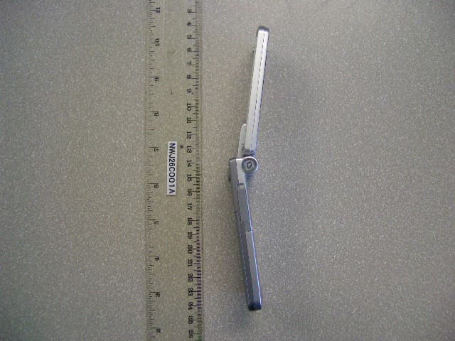
NWJ26C001A
Jun 14, 2005GSM Cellular Mobile Radio
Equipment Class
PCE - PCS Licensed Transmitter held to ear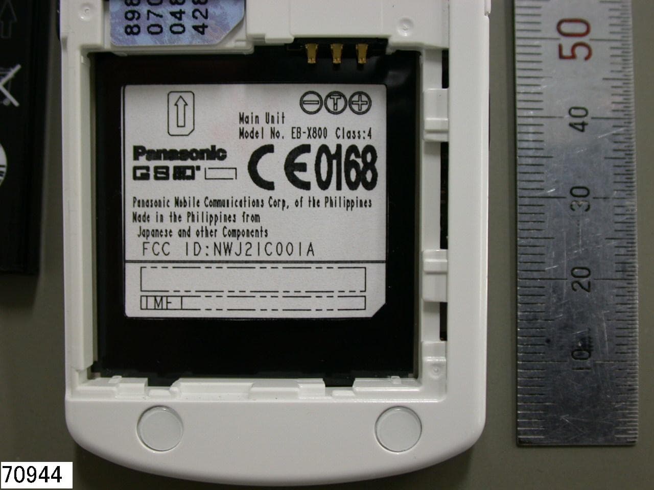
NWJ21C001A
Feb 01, 2005GSM Cellular Mobile Radio
Equipment Class
PCE - PCS Licensed Transmitter held to ear
NWJ22A001A
Nov 04, 2004GSM PCS Handset w/Bluetooth
Equipment Class
DSS - Part 15 Spread Spectrum Transmitter
NWJ22B002A
Feb 26, 2004GSM Cellular Mobile Radio
Equipment Class
PCE - PCS Licensed Transmitter held to ear
NWJ22B001A
Oct 26, 2003GSM Cellular Mobile Radio
Equipment Class
PCE - PCS Licensed Transmitter held to ear