NWJ26C001AGSM Cellular Mobile Radio
Panasonic Mobile Communications Development Corporation of USA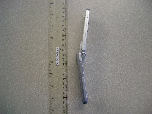
Click to zoom
Application Details
- Equipment Class
- PCE - PCS Licensed Transmitter held to ear
- Date of Grant
- Jun 14, 2005
- Application Purpose
- Original Equipment
- Date of Application
- Jun 14, 2005
- Equipment Note
- GSM Cellular Mobile Radio
- Frequency Range
- 1850.20000000 - 1909.80000000
- Country
- United States
Documents & Files
Document Text
Text extracted from the exhibit documents filed with the FCC. Open a document above to read the original.
Users Manual
1 Safety first Your new phone is a convenient and effective communications tool, but it can be hazardous when used improperly. To avoid harming yourself or anyone else, please review the following information before using your phone. Batteries Batteries can cause property damage, injury, or burns if the terminals are touched with a conductive material (for example, metal jewellery, keys, and so on). Therefore, use caution when handling a charged battery. Additional precautions and notes are listed below: • Never throw a battery into a fire; it may explode. • Fully recharge the battery if the battery is low or as soon as the low-battery alert beeps. • Do not drop the battery. • Do not allow bridging of battery contacts with metallic objects. • Do not remove the battery from the phone while the phone is powered on. Settings you have changed may revert to their previous settings. A recyclable lithium ion/polymer battery powers your phone. Please call 1-800-8-BATTERY for information on how to recycle the battery. Charging devices Use only Genuine Panasonic charging accessories. Use of attachments not recommended by Panasonic or your Service Provider may result in fire, electrical shock, or injury. Panasonic is not responsible for damage caused by using non-Panasonic accessories. • Do not expose charging adapters to moisture, water, or the weather. • Do not use an adapter with a damaged cord. • When using a DC adapter in an automobile, a small amount of electricity flows through the adapter, even if the phone is turned off. Remove the plug from the cigarette lighter whenever the phone will be left in the vehicle for long periods of time. • Always charge the battery in a well ventilated area, not in direct sunlight, between 41°F (5°C) and 95°F (35°C). It is not possible to recharge the battery if it is outside this temperature range. • Do not incinerate or dispose of the battery as ordinary trash. The battery must be disposed of in accordance with local legislation and may be recycled. Caution: The cigarette lighter must have a 12V negative ground socket. Do not use the adapter in a vehicle that has a positive ground system. General • Do not use the phone in extreme temperature or humidity. The specified operating temperature range is -22°F to +140°F (-30°C to +60°C). • Extreme temperatures may have a temporary effect on the operation of your phone. This is normal and does not indicate a fault. • Do not expose the phone (particularly the display) to direct sunlight for extended periods of time or to a humid, dusty or hot area. • Do not attempt to disassemble the phone. There are no user-serviceable parts inside. 2 • Do not subject the equipment to excessive vibration or shock. • Do not expose the phone to rain or spill liquids on it. If the equipment becomes wet immediately remove the battery and charging device and contact your dealer. • Do not use any accessories other than those designed for use with your phone. • Use of attachments not recommended or sold by Panasonic or your Service Provider may result in fire, electrical shock, or injury. • Panasonic is not responsible for damages caused by using non-Panasonic accessories. • Pressing any of the keys may produce a loud tone. Avoid holding the phone close to the ear while pressing the keys. • Keep metallic items that may accidentally touch the battery terminals away from the equipment. Battery damage may occur. • When disposing of any packing materials or old equipment check with your local authorities for information on recycling. • If connecting the phone to an external source, read the operating instructions of the equipment for the correct connection and safety precautions. • If connecting the phone to an external source, verify that the phone is compatible with the product to which you are connecting it. Availability of service This phone, like any wireless phone, operates using radio signals, wireless and landline networks, and user-programmed functions. Because of this, connection in all conditions cannot be guaranteed. Therefore, you should never rely solely on any wireless phone for essential communications (for example, medical emergencies). Emergency (911) service If you need to make an emergency (911) call, power the phone on, dial 911, and press D. Emergency calls can be made regardless of lock setting and with or without a SIM card. Remember, to make or receive any call, the phone must be switched on and in a service area that has adequate signal strength. Even if you are within the coverage area of your Service Provider, you may be in an area with insufficient signal strength to place a 911 call. Emergency calls might not be possible on all wireless phone networks or when certain network service and/or phone features are in use. 3 Safety tips Following the suggestions in this section will help ensure safe and efficient operation of your Panasonic phone. This Model Phone Meets The Government’s Requirements For Exposure To Radio Waves. Your wireless phone is a radio transmitter and receiver. It is designed and manufactured not to exceed the emission limits for exposure to radiofrequency (RF) energy set by the Federal Communications Commission of the U.S. Government. These limits are part of comprehensive guidelines and establish permitted levels of RF energy for the general population. The guidelines are based on standards that were developed by independent scientific organizations through periodic and thorough evaluation of scientific studies. The standards include a substantial safety margin designed to assure the safety of all persons, regardless of age and health. The exposure standard for wireless mobile phones employs a unit of measurement known as the Specific Absorption Rate, or SAR. The SAR limit set by the FCC is 1.6W/kg. Tests for SAR are conducted using standard operating positions specified by the FCC with the phone transmitting at its highest certified power level in all tested frequency bands. Although the SAR i…
Text truncated - open the document above for the full version.
Users Manual
73 Messaging Vodafone Mail Vodafone Mail is an innovative service that lets you stay up-to- date with all of your messages. You need to subscribe to this service. For further information, contact Vodafone. Connecting to internet maild Main menu > Messaging > Vodafone Mail Your phone is connected to the Internet via a WAP connection to retrieve e-mail messages. 1. Follow the screen contents Vodafone Messenger Vodafone Messenger lets you en joy the fun of instant messaging wherever you are. It’s the fun way to chat on-line. For further information, contact Vodafone. Viewing Vodafone Messengerd Main menu > Messaging > Vodafone Messenger 1. Follow the screen contents Voicemail Voicemail is a network service which allows callers, who could not reach you, to leave voice messages. You may need to subscribe to this service. Fo r further information, contact Vodafone. Retrieving stored voice messagesWhen a new voice message is stored, an alert sounds and ( ) appears on the display, and you receive an SMS notification.When an SMS notification is displayed on standby screen: 1. [ 0 ] 9 [ 5 ] (Call) 2. Follow the recorded instructions ORd Main menu > Messaging > Voicemail > Call Voicemail 1. Follow the recorded instructions Shortcut: You can also press and hold [ A ] in standby mode to call your voice mailbox. 74 Messaging Changing the voice mailbox numberd Main menu > Messaging > Voicemail > Set mailbox number 1. Enter new voice mailbox number 7 [ 0 ] 9 [ 5 ] (Ok) Media Album You can store your personal pi ctures, sound/video clips and MMS messages on your online album and share them with family and friends. You need to subscribe to this service. For further information, contact Vodafone. Uploading picturesd Main menu > Messaging > Media Album 1. Follow the screen contents Messaging settings MMS settingsd Main menu > Messaging > Messaging settings > MMS 1. Select the required setting Reports Select Request read (check if the other party has read the message), Send read (inform the other party that you have read the message when asked), Request delivery (check if the other party has received the message) or Send delivery (inform the other party that you have received the message when asked). Priority Select Low , Normal or High for the message priority level. Validity period Set a time period for the message centre to attempt message delivery. Select 1 day , 7 days or Maximum . 75 Messaging * 1 SMS settingsd Main menu > Messaging > Messaging settings > SMS 1. Select the required setting Auto download Select Always (messages are retrieved automa tically after receiving message notifications), On when home (messages are retrieved automati cally in your service area) or Never (messages are retrieved manually). Player mode Select Auto (display MMS slides, or playback video/sound clips automatically) or Manual (display MMS slides, or playback video/sound clips manually). Message font size Select the required font size. Advanced If required, edit the information on Message server , WAP profiles , Fetch on server * 1 and Anonymous reject * 1 . Select Information to view MMS software information. Message lights Decide whether or not you want the Indicator/Illumination Light to illuminate when receiving an illumination message. Message lights view Decide whether or not you want the Indicator/Illumination Light to illuminate when viewing an illumination message. Message centre Edit the message centre number. Message type Select the required message type. Validity period Set a time period for the message centre to attempt message delivery. Select 1 hour , 12 hours , 1 day , 1 week , 1 month , 3 months or Maximum . Delivery report Select On to receive delivery reports. 76 Messaging Memory status You can see the amount of memory available for storing messages.d Main menu > Messaging > Memory status > MMS or SMS Store sent SMS Select On to store sent messages to the Sent folder. Message font size Select the required font size. Bearer type Select the data bearer type. One push SMS Select On to display new SMS messages by opening the flip. Note: To decrease the amount of phone memory used, delete unwanted data or store data on your PC (see “USB” on page 107). 77 Vodafone live! Vodafone live! menu structure Vodafone live!What’s NewGamesRingtonesPicturesNewsSport Note: There are several ways to select items from menu lists. See “Menu selection method” on page 24. 78 Vodafone live! Viewing Vodafone live! Vodafone live! allows yo u to access useful services and download latest ringtones, great pictures and much more. For further information on the services, contact Vodafone. Connecting to Vodafone live!d Main menu > Vodafone live! 1. [ 192 ] to scroll to the required menu 7 [ 0 ] The phone is connected to the web site. Online status iconsDisconnecting from Vodafone live! 1. [ 5 ] (Options) 7 Select Exit browser Shortcut: You can directly access the Vodafone live! web site by pressing [ 6 ] ( } live!) in standby mode. Non-secure CSD connectionSecure CSD connectionNon-secure GPRS connectionSecure GPRS connection 79 Vodafone live! Browser options While Browser is on-line or off-line, the following options are available.d Main menu > Vodafone live! [Off-line] ORd Main menu > Vodafone live! > Required menu [On-line] 1. [ 5 ] (Options) 7 Select the required option * 1 Available only when the web page is displayed. * 2 Available only when the web pa ge has the image, melody or video contents. BookmarksOnce you bookmark your favourite page or a frequently accessed page, you can jump to the page quickly. You can also categorise the bookmarked pages into 10 fo lders and rename each folder. While off-line or on-line: 1. [ 5 ] (Options) 7 Select Bookmarks 2. [ 192 ] to scroll to the required bookmark folder 7 [ 0 ] 3. [ 192 ] to scroll to the required bookmark 4. To load the URL: [ 0 ] To select the required option: [ 5 ] (Options) Select Select the required item. Bookmarks Go to the bookmark list. Enter address Go to URL entry. S…
Text truncated - open the document above for the full version.
Block Diagram
Leopard project Document Number: BSDC-S-H2-10-20041220-1 Issue: 1.0 Page 9 of 30 [BSDC, Confidential, Indefinite, Distribution in IFX&PMC] Confidential Indefinite 3 System Block diagram 3.1 EB-VS3 Block Diagram IrDA KMEC CND0204A 1.3M Camera Micron Main LCD TMDT TFT 2,2'' QVGA HS Amp. LM4809 Baseband LSI S-GOLDlite v1.1 G14 PM 8875 ARM926EJ-S 104MHz TEAKlite 104MHz 256Mb FLASHROM Power Management LSI S/M-Power v1.62 PMB6812 SmatiSD PMB6270 IO connector SIM card Companion IC S1D13756 Melody IC YMU762C Keypad 7x7 Speaker MIC HSJ Receiver I2C Serial DIF IQ and RF control IrDA interface demultiplexed 16-bit parallel data bus 8bit GPIO x3 SIM Interface 7x7 RGB[0:17] Vibrator LED Key Backlight Battery Li+ ion Charger Backup capacitor Direct USB OnTheGo IF USART Power Amp. SKY77328 Antenna Sw. ASM4518806T Antenna Current Monitor ZXCT1010 128Mb SDRAM 256Mb FLASHROM DC/DC PQ6CB11X1BP LCD Backlight YUVI2C 16bit 16bit 16bit MIC RCVOUT SPKOUT Flip sensor EW-6671-FT Power & Battery Audio Visual Phone function Data Communication LED PF38F4460LVYTB0 Tri-color LED PWM R/G/B EB-VS3 System Block Diagram Main LCD TMDT TFT 2.5'' QVGA Sub LCD (UltraChip) IrDA KMEC CND0204A 2.0M Camera Micron HS Amp. LM4809 Baseband LSI S-GOLDlite v1.1 G14 PM 8875 ARM926EJ-S 104MHz TEAKlite 104MHz 256Mb FLASHROM Power Management LSI S/M-Power v1.62 PMB6812 SmatiSD PMB6270 IO connector Bluetooth BlueMoon PMB8761 SIM card Companion IC S1D13756 Melody IC YMU762C Keypad 7x7 Speaker MIC HSJ Receiver I2C Serial DIF IQ and RF control I2S1(PCM) V24 (HCI) IrDA interface demultiplexed 16-bit parallel data bus 8bit GPIO x3 SIM Interface 7x7 RGB[0:17] Vibrator LED Key Backlight Battery Li+ ion Charger Backup capacitor Direct USB OnTheGo IF USART Power Amp. SKY77328 Antenna Sw. ASM4518806T Antenna Current Monitor ZXCT1010 128Mb SDRAM 256Mb FLASHROM DC/DC PQ6CB11X1BP LCD Backlight YUVI2C Serial IF 16bit 16bit 16bit MIC RCVOUT SPKOUT Flip sensor EW-6671-FT Power & Battery Audio Visual Phone function Data Communication LED PF38F4460LVYTB0 Tri-color LED PWM R/G/B Figure 3-2 X600 System Block Diagram Micron
Parts List/Tune Up Info
FORM A OPERATION DESCRIPTION – FOR DEVICES OTHER THAN PARTS 11, 15 AND 18 OF THE FCC RULES This form will be used for the evaluation of devices other than parts 11, 15 and 18 of the FCC rules. Please complete and return along with your other supporting exhibits. SECTION A Type of Emission Please state what Type of Emission(s) your device(s) has. Refer to FCC part 2.201 and 2.202 for more information. Device Name/Model Emission Type Description Emission Type Code NWJ26C001A / EB-VS3 GMSK Phase modulation (0.2Mhz channel spacing) 330KGXW SECTION B Frequency Range Please state what frequency range(s) your device(s) operates over. Please provide “From” and “To” frequencies. Device Name/Model Frequency Range (MHz) NWJ26C001A / EB-VS3 T/X 1850MHz – 1910MHz R/X 1930MHz – 1990MHz SECTION C Range of Operating Power Please state the range(s) your device(s) operates over, and how the power adjustment is controlled. Device Name/Model Power Range (W) Power Control NWJ26C001A / EB-VS3 0.001 – 1.0 Watts Controlled by RF power detection and voltage control on PA gain control pin. SECTION D Maximum Power Rating Please specify the maximum power rating(s) of your device(s) as defined in the applicable part(s) of the FCC rules. Device Name/Model Max Power (W) FCC Part NWJ26C001A / EB-VS3 2.0 Watts 24.232 SECTION E DC Voltages Please specify the DC voltages applied to the DC currents into the several elements of the final radio frequency amplifying device for normal operation over the power range. Device Name/Model Power Level DC Voltage Component NWJ26C001A / EB-VS3 Max power (1.0 W) 3.7VDC nominal, 2.5A RF Power Amplifier (PA) SECTION F Tune Up Procedure Please provide Information about your Tune Up Procedure over the power range (previously specified) or at the specific power levels (also specified). For equipment employing digital modulation techniques, a detailed description of the modulation system to be employed must be provided. This will at least include the response characteristics (Frequency, Phase and Amplitude) or any filters provided, and a description of the modulation wave train, this shall be submitted for the maximum rated conditions under which the equipment will be operated. See details in document below Panasonic Panasonic Mobile Communications Development of Europe Limited Supplement to FCC Form A. Model: EB-VS3 FCC ID: NWJ26C001A Function of the Active Devices-- Pursuant 2.983 (d6) Transmitter U102 SKY77328-13 Tri Band PA Module Receiver U101 PMB6270V V1.1 Transceiver IC U103 ASM4518806T-2505P Antenna Switch Module Synthesizer U401 MAA3278A VCTCXO Power control U3002 PQ6CB11X1BP DCDC IC U900 PMB6812 V1.62 Regulator IC Q902 RTQ035P02L02TR Switching Transistor U500 PMB8875 V1.18 G14 Base Band IC Panasonic Mobile Communications Development of Europe Limited 2 Gables Way, Colthrop, Thatcham, Berkshire RG19 4ZB Tel: +44 (0) 1635 871466 Fax: +44 (0) 1635 871345 VAT Reg No. GB765338211 Web: www.panasonicmobile.com egistered in England No. 4188880 Panasonic Panasonic Mobile Communications Development of Europe Limited Circuit Descriptions A. Means for Stabilizing Transmitter Output Frequency To meet requirements of Subpart J Section 2.983(d10) As a result of the following approach, the frequency stabilization requirement is achieved 1. Phase Locking A Voltage Controlled local Oscillator (VCO) whose frequency output is divided in 1/2 and 1/4 to produce the desired RF frequency produces the transmitter carrier. The oscillator is phase locked to a reference oscillator by an independent PLL (Phased Locked Loop) circuit. The reference oscillator is a Voltage Controlled Temperature Compensated Crystal Oscillator (VCTCXO). Therefore, the transmitter carrier frequency has the same stability as the VCTCXO. 2. VCTCXO The output frequency of the VCTCXO is frequency locked to the RF signal transmitted from a cellular base station by means of an Automatic Frequency Control (AFC) circuit. The received reference signal from the base station is down converted and compared to the mobile station internal frequency. Any differences between the base station reference frequency and the mobile station internal frequency are corrected by fine tuning the VCTCXO frequency. The AFC control circuit is designed such that the transmitter carrier output is maintained within ±0.1ppm of the base station reference frequency. B. Means for Suppressing Spurious Radiation To meet requirements of Subpart J Section 2.983(d-11) As a result of the following approach, the attenuation requirement for spurious and harmonic radiation is achieved. 1. Shielding The RF and Digital sections are enclosed by 3 shield can enclosures. These enclosures are soldered on the gold plated ground of the PCB. All oscillators are enclosed. 2. Filtering Filtering is provided at ASM (Antenna Switch Module). Low pass filters contained in the ASM are separated by band. One filter is provided for 900MHz operation and Another one is provided for 1800 & 1900 MHz operation. Panasonic Mobile Communications Development of Europe Limited 2 Gables Way, Colthrop, Thatcham, Berkshire RG19 4ZB Tel: +44 (0) 1635 871466 Fax: +44 (0) 1635 871345 VAT Reg No. GB765338211 Web: www.panasonicmobile.com egistered in England No. 4188880 Panasonic Panasonic Mobile Communications Development of Europe Limited C. Means for limiting Transmitter Output Power To meet requirements of Subpart J Section 2.983(d-11) The PA module employed in the design contains an integrated power control function. This power control method is based on control of collector current. A high-speed control loop is incorporated to regulate the collector current of the amplifier while maintaining a constant bias on each of the gain stages. By regulating collector current, the amplification stages are held in saturation across all power levels. As a result, output power fluctuations associated with variation in the supply voltage, input power, and temperature are minimized. A control voltage provided by the base…
Text truncated - open the document above for the full version.
RF Exposure Info
REPORT ON Specific Absorption Rate Testing of the Panasonic EB-VS3 Tri-Band GSM 900; GSM1800 and GSM1900 Mobile Handset Report No WS614062/01 Issue 1 June 2005 Competence. Certainty. Quality. TUV Product Service Ltd, Octagon House, Concorde Way, Segensworth North, Fareham, Hampshire, United Kingdom, PO15 5RL Tel: +44 (0) 1489 558100. Website: www.tuvps.co.uk ; www.babt.com Report Number WS614062/01 Issue 1 Page 1 of 37 REPORT ON: Specific Absorption Rate Testing of the Panasonic EB-VS3 Tri-Band GSM 900; GSM1800 and GSM1900 Mobile Handset Report No: WS614062/01 Issue 1 PREPARED FOR: Panasonic Mobile Communications of Europe Ltd (PMCDE) Daytona Drive Colthrop THATCHAM Berkshire RG19 4ZD ATTESTATION: The wireless portable device described within this report has been shown to be capable of compliance for localised specific absorption rate (SAR) for General Population/Uncontrolled Exposure Limits as defined in the FCC standard Supplement C (Edition 01-01) to OET Bulletin 65 (Edition 97-01) of 1.6W/kg. The measurements shown in this report were made in accordance with the procedures specified in OET Bulletin 65 (Edition 97-01). All reported testing was carried out on a sample of equipment to demonstrate compliance with the above standards. The sample tested was found to comply with the requirements in the applied rules. V Kerai SAR Test Engineer APPROVED BY: M J Hardy GSM/SAR Test Manager DATED: 8 th June 2005 DISTRIBUTION: Mobile Communications of Europe Ltd Copy No: 1 BABT Copy No.: 2 Copy No.: 1 Note: The test results reported herein relate only to the item tested as identified above and on the Status Page. Report Number WS614062/01 Issue 1 Page 2 of 37 CONTENTS Section Page No 1 REPORT SUMMARY 1.1 Status .............................................................................................................................. 4 1.2 Summary .......................................................................................................................... 5 1.3 Test Results Summary ..................................................................................................... 6 2 TEST DETAILS 2.1 SAR Measurement System .............................................................................................. 9 2.1.1 Robot System Specification 2.1.2 Probe and Amplifier Specification 2.1.3 SAR Measurement Procedure 2.2 Test Positions ................................................................................................................. 14 2.3 SAR Distributions (Area Scans – 2D)............................................................................. 15 3 TEST EQUIPMENT USED 3.1 Table of Test Equipment Used ...................................................................................... 26 3.2 Test Software ................................................................................................................. 26 3.3 Dielectric Properties of Simulant Liquids........................................................................ 27 3.4 Test Conditions............................................................................................................... 28 3.5 Measurement Uncertainty .............................................................................................. 29 4 PHOTOGRAPHS 4.1 Test Positional Photographs .......................................................................................... 31 4.2 Photographs of Test Samples.. ...................................................................................... 34 5 ACCREDITATION, DISCLAIMERS AND COPYRIGHT 5.1 Accreditation, Disclaimers and Copyright....................................................................... 37 ANNEX A Probe Calibration Procedure ......................................................................................... A.2 Report Number WS614062/01 Issue 1 Page 3 of 37 SECTION 1 REPORT SUMMARY Specific Absorption Rate Testing of the Panasonic EB-VS3 Tri-Band GSM 900; GSM1800 and GSM1900 Mobile Handset Max 1g SAR (W/kg) 0.833 The maximum 1g volume averaged SAR level measured for all the tests performed did not exceed the 1.6 W/kg level for General Population/Uncontrolled Exposure Limits as defined in the FCC standard Supplement C (Edition 01-01) to OET Bulletin 65 (Edition 97-01) of 1.6 W/kg. In accordance with the procedures specified in OET Bulletin 65 (Edition 97-01). Report Number WS614062/01 Issue 1 Page 4 of 37 1.1 STATUS MANUFACTURING DESCRIPTION Tri Band Mobile Handset STATUS OF TEST Specific Absorption Rate Testing APPLICANT Panasonic Mobile Communications of Europe Ltd (PMCDE) GSM POWER CLASS Class 1 (GSM 1900) GPRS CLASS Class B GPRS MULTI-SLOT CLASS Class 10 MANUFACTURER Panasonic Limited TYPE OR MODEL NUMBER Panasonic EB-VS3 HARDWARE VERSION Rev D SOFTWARE VERSION VS3-VA03 SERIAL NUMBER IMEI 004400013139363 BATTERY CELL MANUFACTURER Sanyo GS Soft Energy Company Ltd (SGS) MODEL NUMBER EB-BS001 TEST SPECIFICATIONS: 1. US Federal Government, Code of Federal Regulations, Title 47 Telecommunication, Chapter I Federal Communications Commission, part 2, section 1093. 2. Federal Communications Commission (FCC) OET Bulletin 65c, Edition 01-01, Evaluating Compliance with FCC Guidelines for Human Exposure to Radiofrequency Electromagnetic Fields – Additional Information for Evaluating Compliance of Mobile and Portable Devices with FCC Limits for Human Exposure to Radiofrequency Emissions. REFERENCES: 3. IEEE 1528 – 2003: Recommended Practice for Determining the Peak Spatial-Average Specific Absorption Rate (SAR) in the Human Body Due to Wireless Communications Devices: Experimental Techniques BABT REGISTRATION NUMBER: WS614062 RECEIPT OF TEST SAMPLES: 5 th May 2005 START OF TEST: 9 th May 2005 FINISH OF TEST: 10 th May 2005 Report Number WS614062/01 Issue 1 Page 5 of 37 1.2 SUMMARY The Panasonic EB-VS3 handset supplied for Specific Absorption Rate (SAR) testing is a handset supporting GSM and GPRS functionality in the GSM900; GSM1800 an…
Text truncated - open the document above for the full version.
Test Report
REPORT ON Limited FCC CFR 47: Parts 15 and 24 Testing in support of an Application for Grant of Equipment Authorisation of an EB-VS3 GSM Cellular Phone FCC ID: NWJ26C001A COMMERCIAL-IN-CONFIDENCE Report No OR614062/01 Issue 1 June 2005 Competence. Certainty. Quality TUV Product Service Ltd, Octagon House, Concorde Way, Segensworth North, Fareham, Hampshire, United Kingdom, PO15 5RL Tel: +44 (0) 1489 558100. Website: www.tuvps.co.uk ; www.babt.com Report No OR614062/01 Issue 1 Page 1 of 104 COMMERCIAL-IN-CONFIDENCE REPORT ON Limited FCC CFR 47: Parts 15 and 24 Testing in support of an Application for Grant of Equipment Authorisation of an EB-VS3 GSM Cellular Phone FCC ID: NWJ26C001A Report No OR614062/01 Issue 1 June 2005 PREPARED FOR Panasonic Mobile Communications of Europe Ltd (PMCDE) 2 Gables Way Colthrop Thatcham Berkshire RG19 4ZB PREPARED BY R E Small Test Engineer APPROVED BY K W Adsetts M J Hardy UKAS Signatory UKAS Signatory DATED 9 th June 2005 DISTRIBUTION Panasonic Mobile Communications of Europe Ltd (PMCDE) Copy 1 TUV Product Service Ltd Copy 2 Copy No ENGINEERING STATEMENT The measurements shown in this report were made in accordance with the procedures described on test pages. All reported testing was carried out on a sample equipment to demonstrate limited compliance with FCC CFR 47: Parts 15 and 24. The sample tested was found to comply with the requirements defined in the applied rules. Test Engineers; R E Small P J Harrison A R Hubbard G Lawler FCC ID: NWJ26C001A COMMERCIAL-IN-CONFIDENCE Report No OR614062/01 Issue 1 Page 2 of 104 COMMERCIAL-IN-CONFIDENCE CONTENTS Section Page No 1 REPORT SUMMARY 1.1 Status.................................................................................................................................. 4 1.2 Introduction ......................................................................................................................... 5 1.3 Brief Summary of Results................................................................................................... 5 1.4 Opinions and Interpretations .............................................................................................. 6 1.5 Product information............................................................................................................ 7 1.6 Test Conditions................................................................................................................... 7 1.7 Deviations from the Standard ............................................................................................. 7 1.8 Modification Record............................................................................................................ 7 2 TEST DETAILS 2.1 Maximum Peak Output Power (Conducted)....................................................................... 9 2.2 Modulation Characteristics ................................................................................................. 11 2.3 Occupied Bandwidth .......................................................................................................... 14 2.4 Spurious Emissions At Antenna Terminals (+/- 1MHz)...................................................... 17 2.5 Conducted Emissions On Power Lines.............................................................................. 51 2.6 Conducted Spurious Emissions ......................................................................................... 53 2.7 Frequency Stability Under Temperature Variation ............................................................. 96 2.8 Frequency Stability Under Voltage Variation ..................................................................... 98 3 TEST EQUIPMENT USED 3.1 Table of Test Equipment Used ........................................................................................... 101 3.2 Measurement Uncertainty ......................…
Text truncated - open the document above for the full version.
Contact Information
Applicant
Pieter C. Seidel(Manager of Hardware Verification)
Technical Contact
Panasonic Mobile Communications Development LtdMike L Hargreaves
[email protected]+44 1635 587734
2 Gables Way · Thatcham · United Kingdom
Test Firm
TUV SUD Product ServiceJensen Adams
Technical Specifications
| # | Rule Parts | Frequency Range | Power Output | Emission | Tolerance |
|---|---|---|---|---|---|
| 1 | 24E | 1.85 GHz - 1.91 GHz | 1.55 W | 330KGXW | 800.0000000000 Hz |
Other Applications from Panasonic Mobile Communications Development Corporation of USA
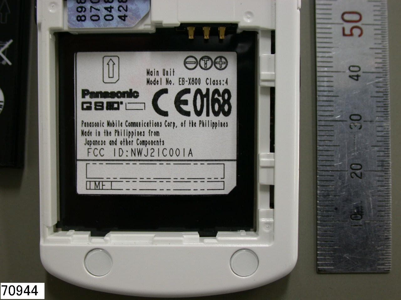
NWJ21C001A
Feb 01, 2005GSM Cellular Mobile Radio
Equipment Class
PCE - PCS Licensed Transmitter held to ear
NWJ22A001A
Nov 04, 2004GSM PCS Handset w/Bluetooth
Equipment Class
DSS - Part 15 Spread Spectrum Transmitter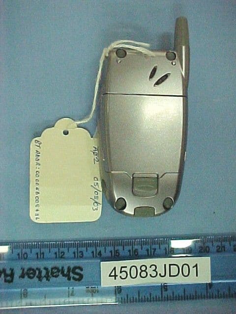
NWJ22B002A
Feb 26, 2004GSM Cellular Mobile Radio
Equipment Class
PCE - PCS Licensed Transmitter held to ear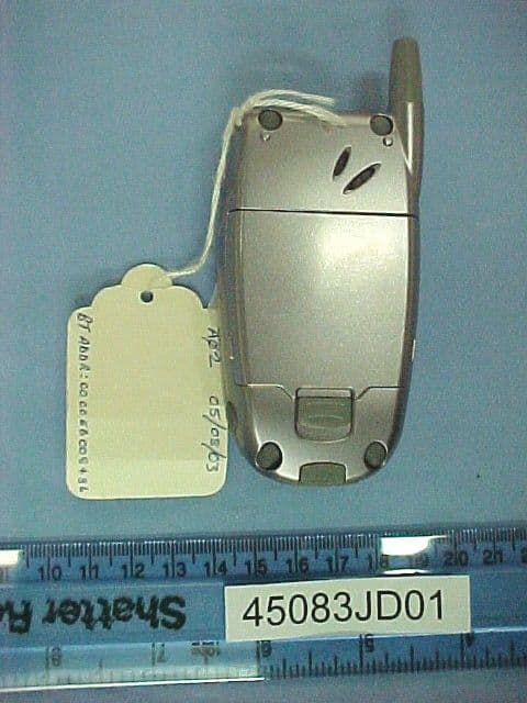
NWJ22B001A
Oct 26, 2003GSM Cellular Mobile Radio
Equipment Class
PCE - PCS Licensed Transmitter held to ear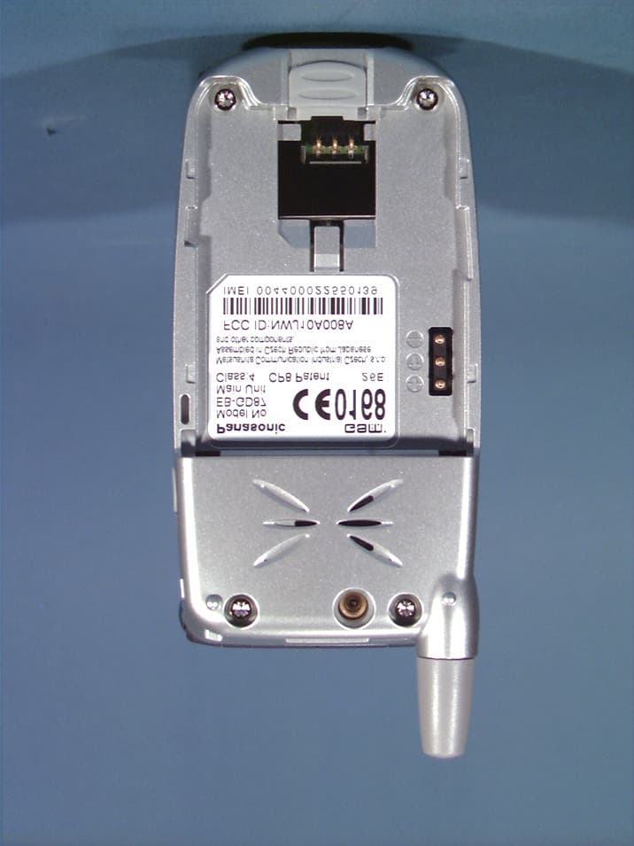
NWJ10A008A
Aug 11, 2002Single-Band PCS GSM Phone
Equipment Class
PCE - PCS Licensed Transmitter held to ear