NWJ10A002ATri-Mode cellular telephone
Panasonic Mobile Communications Development Corporation of USA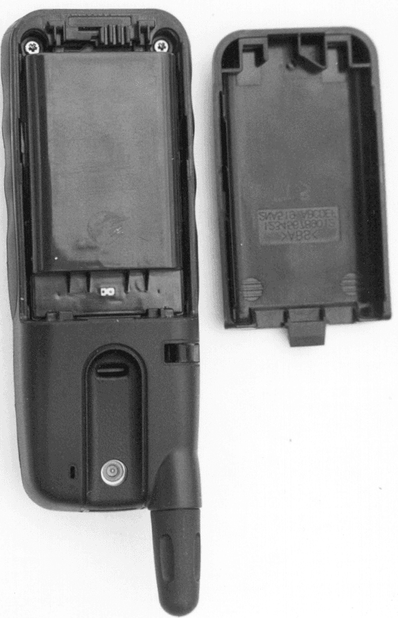
Click to zoom
Application Details
- Equipment Class
- TNB - Licensed Non-Broadcast Station Transmitter
- Date of Grant
- Sep 05, 2000
- Application Purpose
- Original Equipment
- Date of Application
- May 07, 2000
- Equipment Note
- Tri-Mode cellular telephone
- Frequency Range
- 1850.04000000 - 1909.95000000
- Country
- United States
Documents & Files
Document Text
Text extracted from the exhibit documents filed with the FCC. Open a document above to read the original.
Users Manual
Chapter 1 2 Safety First General 1 Do not use the phone in extreme temperature or humidity. The specified operating temperature range is -22°F to +140°F (-30°C to +60°C). 2 Do not attempt to disassemble the phone. There are no user- serviceable parts inside. 3 Do not expose the phone to rain or spill liquids on it. 4 Do not carry the phone by holding the antenna. 5 Do not use any accessories other than those designed for use with your phone. 6 Use of attachments not recommended or sold by your wireless service provider may result in fire, electrical shock, or injury. 7 Panasonic cannot be held responsible for damages caused by using non-Panasonic accessories. Emergency (911) Service If you need to make an emergency (911) call, power the phone on, dial 911, and press . If you have stored the numbers 911 in memory location number 9, simply press and hold 9, and the emergency call will be placed. Emergency calls can be made regardless of lock setting. Safety Tips Following the suggestions in this section will help ensure safe and efficient operation of your Panasonic phone. This Model Phone Meets The Government's Requirements For Exposure To Radio Waves. Your wireless phone is a radio transmitter and receiver. It is designed and manufactured not to exceed the emission limits for exposure to radiofrequency (RF) energy set by the Federal Communications Commission of the U.S. Government. These limits are part of comprehensive guidelines and establish permitted levels of RF energy for the general population. The guidelines are based on standards that were developed by independent scientific organizations through periodic and thorough evaluation of scientific studies. The standards Safety (1).fm Page 2 Wednesday, August 30, 2000 1:11 PM Chapter 1 Safety First 3 include a substantial safety margin designed to assure the safety of all persons, regardless of age and health. The exposure standard for wireless mobile phones employs a unit of measurement known as the Specific Absorption Rate, or SAR. The SAR limit set by the FCC is 1.6W/kg. * Tests for SAR are conducted using standard operating positions specified by the FCC with the phone transmitting at its highest certified power level in all tested frequency bands. Although the SAR is determined at the highest certified power level, the actual SAR level of the phone while operating can be well below the maximum value. This is because the phone is designed to operate at multiple power levels so as to use only the power required to reach the network. In general, the closer you are to a wireless base station antenna, the lower the power output. Before a phone model is available for sale to the public, it must be tested and certified to the FCC that it does not exceed the limit established by the government-adopted requirement for safe exposure. The tests are performed in positions and locations (e.g., at the ear and worn on the body) as required by the FCC for each model. The highest SAR value for this model phone when tested for use at the ear is 1.49W/kg and when worn on the body, as described in this user guide, is .91W/kg. (Body-worn measurements differ among phone models, depending upon available accessories and FCC requirements). While there may be differences between the SAR levels of various phones and at various positions, they all meet the government requirement. The FCC has granted an Equipment Authorization for this model phone with all reported SAR levels evaluated as in compliance with the FCC RF emission guidelines. SAR information on this model phone is on file with the FCC and can be found under the Display Grant section of http://www.fcc.gov/oet/fccid after searching on FCC ID NWJ10A002A. * In the United States and Canada, the SAR limit for mobile phones used by the public is 1.6 watts/kg (W/kg) averaged over one gram of tissue. The standard incorporates a substantial margin of safety to give additional protection for the public and to account for any variations in measurements. Safety (1).fm Page 3 Wednesday, August 30, 2000 1:11 PM Chapter 1 4 Safety First All Panasonic branded accessories are tested and comply with FCC RF exposure requirements. Non-Panasonic accessories may not comply. Body-worn operation To maintain compliance with FCC RF exposure guidelines, if you wear your wireless phone on your body while on a voice or data call, always place the phone in a Panasonic supplied or approved carry accessory. Use of non-Panasonic approved accessories may exceed FCC RF exposure guidelines. Antenna Care Use only the supplied or an approved replacement antenna. Unauthorized antennas, modifications, or attachments could damage the phone and may violate FCC regulations. Phone Operation NORMAL POSITION: Hold the phone as you would any other telephone, with the antenna pointed up and over your shoulder. FOR EFFICIENT OPERATION: For your phone to operate most efficiently, do not touch the antenna unnecessarily when the phone is in use. Contact with the antenna affects call quality and may cause the phone to operate at a higher power level than otherwise needed. Driving Check the laws and regulations on the use of wireless telephones in the areas where you drive. Always obey them. Also, if using your phone while driving, please: •Give full attention to driving—driving safely is your first responsibility; •Use handsfree operation, if available; •Pull off the road and park before making or answering a call if driving conditions so require. Safety (1).fm Page 4 Wednesday, August 30, 2000 1:11 PM
Cover Letter(s)
Panasonic Matsushita Mobile Communications Development Corporation of U.S.A. FCC ID: NWJ10A002A COVER LETTERS Page 1 of 4 1225 Northbrook Parkway • Suite 2-400 • Suwanee, GA 30024 • Phone (770)338-6000 • Fax (770)338-6210 MATSUSHITA MOBILE COMMUNICATIONS DEVELOPMENT CORPORATION OF U.S.A. Application for Type Acceptance Panasonic Handheld Portable Cellular Telephone FCC ID: NWJ10A002A THIS COVER PAGE IS FOR FILING IDENTIFICATION ONLY Panasonic Matsushita Mobile Communications Development Corporation of U.S.A. FCC ID: NWJ10A002A COVER LETTERS Page 2 of 4 1225 Northbrook Parkway • Suite 2-400 • Suwanee, GA 30024 • Phone (770)338-6000 • Fax (770)338-6210 Date: 5.10.2000 Authorization & Evaluation Division. Federal Communications Commission Laboratory. 7435 Oakland Mills Road. Columbia, MD 21045. Subject: Application for Type Acceptance of Transmitter with FCC ID: NWJ10A002A Gentlemen: Matsushita Mobile Communications Development Corporation of U.S.A. in Suwanee, Ga., herein submits application for type acceptance of the subject transmitter. This transmitter is intended for use in a dual mode – dual band cellular telephone application with capabilities for clear communications with a maximum transmit power of 476 mWatt or 26.8 dBm (Variable Power) down to as low as 0.16 mWatts in TDMA 800 MHz mode. The subject transmitter complies with Section 90.203 of the rules in that the operator cannot directly program transmit frequencies using only the unit's normally accessible external controls. Enclosed is a complete Type Acceptance Application. Contact me (770) 338-6270 if you require any additional information. Best Regards, Pieter C. Seidel Technical Group Leader Systems Test Phone: 770-338-6270 Fax: 770-338-6210 Panasonic Matsushita Mobile Communications Development Corporation of U.S.A. FCC ID: NWJ10A002A COVER LETTERS Page 3 of 4 1225 Northbrook Parkway • Suite 2-400 • Suwanee, GA 30024 • Phone (770)338-6000 • Fax (770)338-6210 Date: 5.10.2000 Authorization & Evaluation Division. Federal Communications Commission Laboratory. 7435 Oakland Mills Road. Columbia, MD 21045. Subject: REQUEST FOR CONFIDENTIALITY Pursuant to sections 0.457 (d) (1) (ii) and 0.459 of the commission’s rules, the applicant hereby requests confidential treatment of some of the information accompanying this application for FCC ID: NWJ10A002A as outlined below: • Block Diagram • Schematics • Theory of operation and circuit descriptions • Users Manual This information contains trade secrets and proprietary information not customarily released to the public. The public disclosure of this information might be harmful to the applicant and provide unjust benefits to its competitors. The applicant understands that pursuant to rule 0.457d, disclosure of this application and all accompanying documentation will not be made before the date of the grant for this application. MMCD Panasonic Best Regards, Pieter C. Seidel Technical Group Leader Systems Test Phone: 770-338-6270 Fax: 770-338-6210 Panasonic Matsushita Mobile Communications Development Corporation of U.S.A. FCC ID: NWJ10A002A COVER LETTERS Page 4 of 4 1225 Northbrook Parkway • Suite 2-400 • Suwanee, GA 30024 • Phone (770)338-6000 • Fax (770)338-6210 LIST OF EXHIBITS DESCRIPTION FCC REFERENCE Cover Letters 1. Cover 2. Letter of Intent 3. Confidentiality statement 4. List of Exhibits I. Attestation Statement2.983(a) II. Identification label information2.983-(f) III. Block Diagrams2.983(d7) IV. Operational Description 1. General Information2.983-(a,b,c) 1. Production Plans2.981-(c) 2. Application References2.1061 2. Technical Characteristics2.983-(d1,2,3,4,5) 3. Function of Active devices2.983-(d6) 4. Circuit Description 1. Frequency Stabilizing2.983-(d10) 3.Harmonic Suppression2.983-(d11) 2. Modulation Limiting2.983-(d11) 4.Power Limiting2.983-(d11) 5.Attenuating Higher Audio Freq.2.983-(d11) 6.Digital Modulation Techniques2.983-(d12) 7.ESN Protection22.919 V. Schematics2.983-(d7) VI. Tune Procedure / Parts Lists2.983-(d9) VII. Test Report2.983-(e) 1.Data Index 2.RF Output-Data2.985 3.Modulation Characteristics2.987, 22.915 A. Audio Response 2.987(a) B. Low Pass Filter Response2.987(a) C. Modulation Limiting2.987(b) 4. Occupied Bandwidth2.989, 22.917 5. Conducted Spurious Emissions 2.991, 24.238, 22.917(e,f) 6. Radiated Spurious Emissions2.993, 24.238, 22.917(e,f) 7. Frequency Stability (Temp & Supply Volt)2.995 8. Radiated Power22.913, 24.232(b) VIII. RF Exposure - SAR2.1093 IX. Internal Photograph(s)2.983-(g) X. External Photograph(s)2.983-(g) XI. User Manual2.983-(d8) XII. Test System and Measurement Procedure2.999 & 2.947
Cover Letter(s)
Panasonic Matsushita Mobile Communications Development Corporation of U.S.A. Pieter C. Seidel • Technical Group Leader • Direct Phone. 770.338.6270 • [email protected] 1225 Northbrook Parkway • Suite 2-400 • Suwanee, GA 30024 • Phone (770) 338-6000 • Fax (770) 338-6210 This is in response to Correspondence Reference Number: 14561. Pieter This is also enclosed in an attachment. From:Errol Chang [email protected] FCC Application Processing Branch Re:FCC ID NWJ10A002A Applicant:Matsushita Mobile Communications Development Corporation of USA Correspondence Reference Number:14561 731 Confirmation Number:EA97534 Date of Original E-Mail:06/14/2000 Please indicate the name and location of the test lab. ANSWER! *SAR lab Matsushita Communication Engineering Co.,Ltd 4-3-1,Tsunashima-higashi,Kohoku-ku,Yokohama,223-8639,Japan *Radiation test lab. JAPAN QUALITY ASSURANCE ORGANIZATION (JQA) 1-7-7,Ishimaru,Minoo,Ohsaka,562-0027,Japan If you have any questions, please feel free to contact me. Pieter
Cover Letter(s)
Panasonic Matsushita Mobile Communications Development Corporation of U.S.A. Pieter C. Seidel • Technical Group Leader • Direct Phone. 770.338.6270 • [email protected] 1225 Northbrook Parkway • Suite 2-400 • Suwanee, GA 30024 • Phone (770) 338-6000 • Fax (770) 338-6210 Date – 8.31.2000 FCC ID # NWJ10A002A Applicant: Matsushita Mobile Communications Development Corporation of USA Correspondence Reference Number:15390 731 Confirmation Number:EA97534 To: Richard Fabina of the FCC, After reviewing the data refereed to in the request for information attaches below, I see the confusion. The measurements are stated in different modes like peak and average and measurements were done with power meters and spectrum analyzers. The inaccuracy between all of these is too large to reconcile and although all of the data should have been taken with the same units, it appears that different units were mistakenly measured. Panasonic apologizes for the confusion that this has caused. In order to remedy this problem, we have contracted PCTest Engineering laboratories in Columbia, MD to retake the data for SAR on the head and body, radiated emissions, and radiated power all on one phone of each model. By using the same phone, there should be no question of correlation between the power levels used in each test. Included is a complete SAR report that should resolve questions 1 and 2. As you review the data, you will notice that the holster used in the body worn measurements for model EB-TX220 has an AT&T logo. Panasonic does not plan on selling a Panasonic branded holster for this model but we were aware that AT&T was. So in order to provide accurate body worn data for this model we used an AT&T holster. Panasonic in no way claims that we will certify and approve any third party vendors accessories to meet RF exposure guidelines because we have no control over who makes them or how they are made. We simply wanted to provide body worn data to the FCC. In response to question number 3, we have included an attachment of the Operating Instructions safety section. In that you will see that we added the body worn statement to page 4. It still also appears in the accessory section of the OI. The correct maximum SAR values also appear on page 3 of the Safety Section. Below is a list of uploaded attachments that satisfy the request for information copied below: 1)FCC SAR Measurement Report 2)FCC Part 24/22 ERP & EIRP Measurement Report 3)OI Safety Section 8.31.00 4)This letter - FCC Reply 15390 Panasonic Matsushita Mobile Communications Development Corporation of U.S.A. Pieter C. Seidel • Technical Group Leader • Direct Phone. 770.338.6270 • [email protected] 1225 Northbrook Parkway • Suite 2-400 • Suwanee, GA 30024 • Phone (770) 338-6000 • Fax (770) 338-6210 To:Pieter Seidel, null From:Richard Fabina [email protected] FCC Application Processing Branch Re:FCC ID NWJ10A002A Applicant: Matsushita Mobile Communications Development Corporation of USA Correspondence Reference Number:15390 731 Confirmation Number: EA97534 Date of Original E-Mail:08/03/2000 1. Please review the output power summary on page 11 of one of the submitted files in the latest reply. The output power used in the SAR test is up to 1.1 dB lower than the output power used in the EMC tests for the AMPS mode. The output powers used in the SAR tests are more than 3 dB lower then those used in the EMC tests for the 800 MHZ TDMA and PCS modes. Based on the SAR results, setting the conducted output power to the levels used in the EMC tests would cause the SAR limit to be exceeded. The maximum output powers must not exceed those tested for SAR testing in order to maintain compliance. The maximum radiated output (ERP and EIRP) power to be used for the grant must be scaled accordingly with respect to those used in the SAR tests. Please confirm that production units will not exceed the following outputs: for model TX-210 - AMPS mode: 281 mW ERP, TDMA mode: 631 mW ERP and PCS mode: 57 mW EIRP; for model 220 - AMPS mode: 182 mW ERP, TDMA mode: 408 mW ERP and PCS mode: 57 mW EIRP. 2. The device shown in the body-worn SAR plots has its antenna on the wrong side and several of the PCS plots have peak SAR at the edge of the measurement boundary. Please clarify and, if necessary, repeat the measurement with expanded area(s) (DASY has updated software for measurements in cheek and jaw areas). 3. Please revise and relocate body-worn SAR statement and operating instructions. Currently, it is in the accessories section of the user’s manual. Body-worn operating instructions and statements are generally placed in the front part of the manual in a conspicuous location where users can readily see it. These operating instructions and statements should: (1) caution the consumer to use the specific soft holster and leather-carrying case that has been tested for SAR compliance, and (2) warn that other similar accessories that have not been tested may not comply with FCC RF exposure Panasonic Matsushita Mobile Communications Development Corporation of U.S.A. Pieter C. Seidel • Technical Group Leader • Direct Phone. 770.338.6270 • [email protected] 1225 Northbrook Parkway • Suite 2-400 • Suwanee, GA 30024 • Phone (770) 338-6000 • Fax (770) 338-6210 requirements and using them should be avoided. Please upload the relevant page(s) of the revised user’s manual and indicate their location. For your information - The following are the proposed grant conditions at this point of the application processing: Proposed Grant Conditions - Output is ERP for Part 22 and EIRP for Part 24. Device output for all operating modes must not exceed those tested for SAR compliance. SAR compliance for body-worn operating configurations is limited to the specific soft-holster and leather-carrying case tested for this filing. End-users must be informed of the body-worn operating requirements for satisfying RF exposure compliance. The highest reported SAR values for devices auth…
Text truncated - open the document above for the full version.
External Photos
Panasonic Matsushita Mobile Communications Development Corporation of U.S.A. FCC ID: NWJ10A002A EXTERNAL PHOTOGRAPHS Page 1 of 7 1225 Northbrook Parkway • Suite 2-400 • Suwanee, GA 30024 • Phone (770) 338-6000 • Fax (770) 338-6210 EXTERNAL PHOTOGRAPHS The following photographs that are attached show two models the EB-210A (Business Model) and the EB-220A (Durable Model). The internal PCBs and mechanics are identical between the two models. The only differences are the external look and feel. Front View. Panasonic Matsushita Mobile Communications Development Corporation of U.S.A. FCC ID: NWJ10A002A EXTERNAL PHOTOGRAPHS Page 2 of 7 1225 Northbrook Parkway • Suite 2-400 • Suwanee, GA 30024 • Phone (770) 338-6000 • Fax (770) 338-6210 Back Side with Battery View. Panasonic Matsushita Mobile Communications Development Corporation of U.S.A. FCC ID: NWJ10A002A EXTERNAL PHOTOGRAPHS Page 3 of 7 1225 Northbrook Parkway • Suite 2-400 • Suwanee, GA 30024 • Phone (770) 338-6000 • Fax (770) 338-6210 Back Side no Battery View (FCC Label location). Panasonic Matsushita Mobile Communications Development Corporation of U.S.A. FCC ID: NWJ10A002A EXTERNAL PHOTOGRAPHS Page 4 of 7 1225 Northbrook Parkway • Suite 2-400 • Suwanee, GA 30024 • Phone (770) 338-6000 • Fax (770) 338-6210 Back Side no Battery Door View (EB-TX220 only) Panasonic Matsushita Mobile Communications Development Corporation of U.S.A. FCC ID: NWJ10A002A EXTERNAL PHOTOGRAPHS Page 5 of 7 1225 Northbrook Parkway • Suite 2-400 • Suwanee, GA 30024 • Phone (770) 338-6000 • Fax (770) 338-6210 Bottom View of Connector. Top View. Panasonic Matsushita Mobile Communications Development Corporation of U.S.A. FCC ID: NWJ10A002A EXTERNAL PHOTOGRAPHS Page 6 of 7 1225 Northbrook Parkway • Suite 2-400 • Suwanee, GA 30024 • Phone (770) 338-6000 • Fax (770) 338-6210 Side Views. Panasonic Matsushita Mobile Communications Development Corporation of U.S.A. FCC ID: NWJ10A002A EXTERNAL PHOTOGRAPHS Page 7 of 7 1225 Northbrook Parkway • Suite 2-400 • Suwanee, GA 30024 • Phone (770) 338-6000 • Fax (770) 338-6210 Antenna Side View.
External Photos
Test Report S/N: SAR.200824438.NWJ Measurement Report Test Dates: August 25 & 28-30, 2000 PANASONIC FCC ID: NWJ10A002A (Models: EBTX-210/220) © 2000 PCTEST Lab Tri-Mode Dual-Band Phone (AMPS/TDMA) APPENDIX G – EUT PROFILE PHOTOGRAPHS Test Report S/N: SAR.200824438.NWJ Measurement Report Test Dates: August 25 & 28-30, 2000 PANASONIC FCC ID: NWJ10A002A (Models: EBTX-210/220) © 2000 PCTEST Lab Tri-Mode Dual-Band Phone (AMPS/TDMA) PANASONIC Model: EBTX-210 © 2000 PCTEST Lab Panasonic FCC ID: NWJ10A002A (Models: EBTX-210 / 220) NVLAP Lab Code: 1004310 Tri-Mode Dual-Band Phone (AMPS/TDMA) © 2000 PCTEST Lab Panasonic FCC ID: NWJ10A002A (Models: EBTX-210 / 220) NVLAP Lab Code: 1004310 Tri-Mode Dual-Band Phone (AMPS/TDMA) © 2000 PCTEST Lab Panasonic FCC ID: NWJ10A002A (Models: EBTX-210 / 220) NVLAP Lab Code: 1004310 Tri-Mode Dual-Band Phone (AMPS/TDMA) © 2000 PCTEST Lab Panasonic FCC ID: NWJ10A002A (Models: EBTX-210 / 220) NVLAP Lab Code: 1004310 Tri-Mode Dual-Band Phone (AMPS/TDMA) © 2000 PCTEST Lab Panasonic FCC ID: NWJ10A002A (Models: EBTX-210 / 220) NVLAP Lab Code: 1004310 Tri-Mode Dual-Band Phone (AMPS/TDMA) © 2000 PCTEST Lab Panasonic FCC ID: NWJ10A002A (Models: EBTX-210 / 220) NVLAP Lab Code: 1004310 Tri-Mode Dual-Band Phone (AMPS/TDMA) © 2000 PCTEST Lab Panasonic FCC ID: NWJ10A002A (Models: EBTX-210 / 220) NVLAP Lab Code: 1004310 Tri-Mode Dual-Band Phone (AMPS/TDMA) © 2000 PCTEST Lab Panasonic FCC ID: NWJ10A002A (Models: EBTX-210 / 220) NVLAP Lab Code: 1004310 Tri-Mode Dual-Band Phone (AMPS/TDMA) © 2000 PCTEST Lab Panasonic FCC ID: NWJ10A002A (Models: EBTX-210 / 220) NVLAP Lab Code: 1004310 Tri-Mode Dual-Band Phone (AMPS/TDMA) © 2000 PCTEST Lab Panasonic FCC ID: NWJ10A002A (Models: EBTX-210 / 220) NVLAP Lab Code: 1004310 Tri-Mode Dual-Band Phone (AMPS/TDMA) © 2000 PCTEST Lab Panasonic FCC ID: NWJ10A002A (Models: EBTX-210 / 220) NVLAP Lab Code: 1004310 Tri-Mode Dual-Band Phone (AMPS/TDMA) © 2000 PCTEST Lab Panasonic FCC ID: NWJ10A002A (Models: EBTX-210 / 220) NVLAP Lab Code: 1004310 Tri-Mode Dual-Band Phone (AMPS/TDMA) Test Report S/N: SAR.200824438.NWJ Measurement Report Test Dates: August 25 & 28-30, 2000 PANASONIC FCC ID: NWJ10A002A (Models: EBTX-210/220) © 2000 PCTEST Lab Tri-Mode Dual-Band Phone (AMPS/TDMA) PANASONIC Model: EBTX-220 © 2000 PCTEST Lab Panasonic FCC ID: NWJ10A002A (Models: EBTX-210 / 220) NVLAP Lab Code: 1004310 Tri-Mode Dual-Band Phone (AMPS/TDMA) © 2000 PCTEST Lab Panasonic FCC ID: NWJ10A002A (Models: EBTX-210 / 220) NVLAP Lab Code: 1004310 Tri-Mode Dual-Band Phone (AMPS/TDMA) © 2000 PCTEST Lab Panasonic FCC ID: NWJ10A002A (Models: EBTX-210 / 220) NVLAP Lab Code: 1004310 Tri-Mode Dual-Band Phone (AMPS/TDMA) © 2000 PCTEST Lab Panasonic FCC ID: NWJ10A002A (Models: EBTX-210 / 220) NVLAP Lab Code: 1004310 Tri-Mode Dual-Band Phone (AMPS/TDMA) © 2000 PCTEST Lab Panasonic FCC ID: NWJ10A002A (Models: EBTX-210 / 220) NVLAP Lab Code: 1004310 Tri-Mode Dual-Band Phone (AMPS/TDMA) © 2000 PCTEST Lab Panasonic FCC ID: NWJ10A002A (Models: EBTX-210 / 220) NVLAP Lab Code: 1004310 Tri-Mode Dual-Band Phone (AMPS/TDMA) © 2000 PCTEST Lab Panasonic FCC ID: NWJ10A002A (Models: EBTX-210 / 220) NVLAP Lab Code: 1004310 Tri-Mode Dual-Band Phone (AMPS/TDMA) © 2000 PCTEST Lab Panasonic FCC ID: NWJ10A002A (Models: EBTX-210 / 220) NVLAP Lab Code: 1004310 Tri-Mode Dual-Band Phone (AMPS/TDMA) © 2000 PCTEST Lab Panasonic FCC ID: NWJ10A002A (Models: EBTX-210 / 220) NVLAP Lab Code: 1004310 Tri-Mode Dual-Band Phone (AMPS/TDMA)
ID Label/Location Info
Panasonic Matsushita Mobile Communications Development Corporation of U.S.A. FCC ID: NWJ10A002A IDENTIFICATION LABEL Page 1 of 1 1225 Northbrook Parkway • Suite 2-400 • Suwanee, GA 30024 • Phone (770) 338-6000 • Fax (770) 338-6210 IDENTIFICATION LABEL -- Pursuant 2.98 3 (f) The label is a paper polyester film laminate with a pressure sensitive adhesive backing. The adhesive is a permanent type. Business Model Durable Model Model Numbers EB-TX210A - AT&T Business Model EB-TX220A - AT&T Durable Model EB-TX210F - Affiliate Carrier Business Model EB-TX220F - Affiliate Carrier Durable Model EB-TX210C - Canada Business Model EB-TX220C - Canada Durable Model Panasonic Matsushita Mobile Communications Development Corporation of U.S.A. FCC ID: NWJ10A002A IDENTIFICATION LABEL Page 2 of 2 1225 Northbrook Parkway • Suite 2-400 • Suwanee, GA 30024 • Phone (770) 338-6000 • Fax (770) 338-6210 Location of label on the back of the housing. Business Model Durable Model Panasonic Matsushita Mobile Communications Development Corporation of U.S.A. FCC ID: NWJ10A002A IDENTIFICATION LABEL Page 3 of 3 1225 Northbrook Parkway • Suite 2-400 • Suwanee, GA 30024 • Phone (770) 338-6000 • Fax (770) 338-6210 Label Print.
Internal Photos
Panasonic Matsushita Mobile Communications Development Corporation of U.S.A. FCC ID: NWJ10A002A INTERNAL PHOTOGRAPHSPage 1 of 5 1225 Northbrook Parkway • Suite 2-400 • Suwanee, GA 30024 • Phone (770)338-6000 • Fax (770)338-6210 INTERNAL PHOTOGRAPH Internal front view showing PCB with shield and mating Front Cover. Panasonic Matsushita Mobile Communications Development Corporation of U.S.A. FCC ID: NWJ10A002A INTERNAL PHOTOGRAPHSPage 2 of 5 1225 Northbrook Parkway • Suite 2-400 • Suwanee, GA 30024 • Phone (770)338-6000 • Fax (770)338-6210 Internal back view showing PCB with shield and mating Back Cover. Panasonic Matsushita Mobile Communications Development Corporation of U.S.A. FCC ID: NWJ10A002A INTERNAL PHOTOGRAPHSPage 3 of 5 1225 Northbrook Parkway • Suite 2-400 • Suwanee, GA 30024 • Phone (770)338-6000 • Fax (770)338-6210 Front Side PCB with shield removed. Panasonic Matsushita Mobile Communications Development Corporation of U.S.A. FCC ID: NWJ10A002A INTERNAL PHOTOGRAPHSPage 4 of 5 1225 Northbrook Parkway • Suite 2-400 • Suwanee, GA 30024 • Phone (770)338-6000 • Fax (770)338-6210 Back Side PCB with shield removed. Panasonic Matsushita Mobile Communications Development Corporation of U.S.A. FCC ID: NWJ10A002A INTERNAL PHOTOGRAPHSPage 5 of 5 1225 Northbrook Parkway • Suite 2-400 • Suwanee, GA 30024 • Phone (770)338-6000 • Fax (770)338-6210 Front Side PCB with shield removed from Back
Parts List/Tune Up Info
Panasonic Matsushita Mobile Communications Development Corporation of U.S.A. FCC ID: NWJ10A002A TUNE INFORMATIONPage 1 of 22 1225 Northbrook Parkway • Suite 2-400 • Suwanee, GA 30024 • Phone (770) 338-6000 • Fax (770) 338-6210 EV description 1. EV Specification / Tune Procedure This specification contains only the information required for electronic adjustment of the POLARIS handset. The specification contains two sections; the adjustment procedure, and the adjustment range and configuration matrix. Adjustment Procedure – Gives a detailed description of each adjustment of the handset in the required sequence. Adjustment Range and Configuration Matrix – Gives the adjustment parameter, adjustment limits, and default EV value, and brief equipment set up for each adjustment. 1.1. Electronic Adjustment Support – Overview POLARIS will support electronic adjustment of various audio and RF related parameters through an external test set by putting the radio into adjust mode. This document covers the adjustment procedure using the external test set. All adjustments are typically done using channel 350 in the cellular band or channel 1000 in the PCS band unless otherwise specified with the transceiver and audio control set as required for the adjustment. The POLARIS electronic adjustment allows for the setting of the following parameters: ! Battery Reference Voltage ! Charging ! AFC Tuning ! PA-GATE Bias Voltage ! Power Level ! Compressor Reference Level ! Standard Deviation ! Max Deviation ! SAT Deviation ! WBD / ST Deviation ! DTMF Deviation ! Expander Reference Level ! RX Audio Level ! Analog RSSI Calibration ! Digital RSSI Calibration ! PLL IC 1.2. Test Set Adjustment Operation The test set originated adjustments generally operate as follows: 1. Commands are sent as 9600-baud asynchronous serial data with 8 data bits, non-parity and 1 stop bit. Commands are received on the RX data line and responses are sent on the TX data line. All commands are sent through the serial bus in the following format (in hex): 00 80 NN CC (D1) (D2) (D3) ... (Dn) Where NN is the number of bytes sent (command plus data), CC is the command op code, and D1 through Dn are data associated with the command (see individual command below for number of data bytes expected). 2. The adjust mode is entered by first sending the Test Mode and then sending the Adjust Mode command. 3. A set adjustment command (such as Set SA T) is sent to set up the hardware for the specified test with the current adjustment. Panasonic Matsushita Mobile Communications Development Corporation of U.S.A. FCC ID: NWJ10A002A TUNE INFORMATIONPage 2 of 22 1225 Northbrook Parkway • Suite 2-400 • Suwanee, GA 30024 • Phone (770) 338-6000 • Fax (770) 338-6210 4. The Set Current Adjustment Value command is issued along with a value which is used to set the selected adjustment and update the hardware. This may be repeated as necessary until the final adjustment value is determined. 5. The Exit Adjustment Mode command is issued to exit adjustment mode with the option to save all adjustments to nonvolatile memory. Handset returns to test mode. 6. The Exit Active Adjustment Mode command is issued to exit the current adjustment with the option to save to active memory. Handset is still in adjustment mode. 7. When all adjustments are complete, the Normal Mode command can be sent to return the unit to normal operation. 8. ALL RF POWERS LISTED ARE NOT CORRECTED FOR THE INTERNAL TRANSMISSION LINE PATH LOSS. ADD 1.2dB TO ALL RF POWERS IN THE CELLULAR BAND AND 2.2dB TO ALL RF POWERS IN THE PCS BAND TO COMPENSATE FOR THE INTERNAL TRANSMISSION LINE PATH LOSS. 9. Adjustments must be performed at +25 ±5 °C in the order specified. Adjustments performed outside the temperature range may produce erroneous results. 1.3. Enter Adjust Mode Use this command to put the unit under test (UUT) into adjust mode. This must be done before issuing any other adjust commands. 1 Apply DC power (5.8+/-0.2[V]) to DC-PWR-IN at the I/O connector of the UUT. 2 Send Enter Test Mode command and then send Adjust Mode command. 1.4. Battery Reference Voltage Calibration 1 Set power supply as 3.6[V] to the battery terminal and turns on the handset. 2 Enter battery reference voltage calibration mode. 3 Set power supply as 4.2[V] to battery terminal. 4 Then save the ADC2 value. 5 Set power supply as 3.0[V] to battery terminal. 6 Then save the ADC2 value. 7 Exit battery reference voltage calibration mode. 1.5. Charging Calibration 1 Enter charging adjust mode. 2 Set external power supply as 5.8[V] to external power supply port (DC-PWR) battery terminal while the battery load is 84[ohm…
Text truncated - open the document above for the full version.
Contact Information
Applicant
Pieter C. Seidel(Manager of Hardware Verification)
Technical Contact
Panasonic - MMCDPieter C Seidel
[email protected]770-338-6270
1225 Northbrook Pkwy · Suwanee, Georgia · United States
Non-Technical Contact
Panasonic - MMCDPieter C Seidel
[email protected]770-338-6270
Test Firm
Japan Quality Assurance Org.Katsumi Nishii
Technical Specifications
| # | Rule Parts | Frequency Range | Power Output | Emission | Tolerance |
|---|---|---|---|---|---|
| 4 | 24E | 1.85 GHz - 1.91 GHz | 600.00 mW | 256KDXW | 200 Hz |
Other Applications from Panasonic Mobile Communications Development Corporation of USA
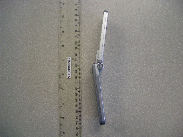
NWJ26C001A
Jun 14, 2005GSM Cellular Mobile Radio
Equipment Class
PCE - PCS Licensed Transmitter held to ear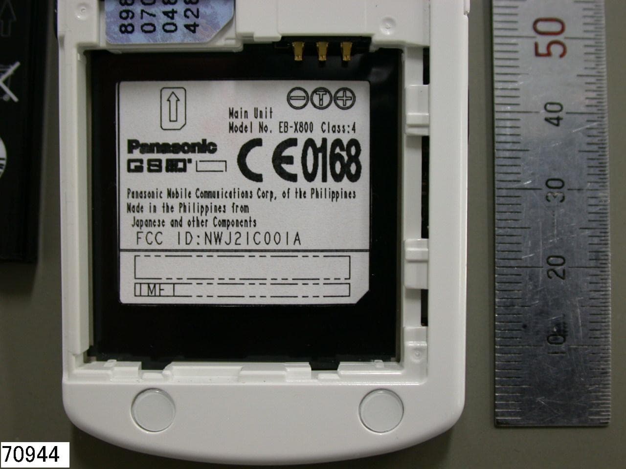
NWJ21C001A
Feb 01, 2005GSM Cellular Mobile Radio
Equipment Class
PCE - PCS Licensed Transmitter held to ear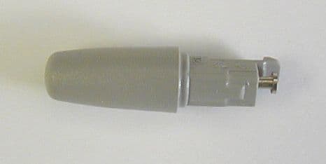
NWJ22A001A
Nov 04, 2004GSM PCS Handset w/Bluetooth
Equipment Class
DSS - Part 15 Spread Spectrum Transmitter
NWJ22B002A
Feb 26, 2004GSM Cellular Mobile Radio
Equipment Class
PCE - PCS Licensed Transmitter held to ear
NWJ22B001A
Oct 26, 2003GSM Cellular Mobile Radio
Equipment Class
PCE - PCS Licensed Transmitter held to ear