OEW-M64-25TurboMax Base Station
ADC Telecommunications Inc.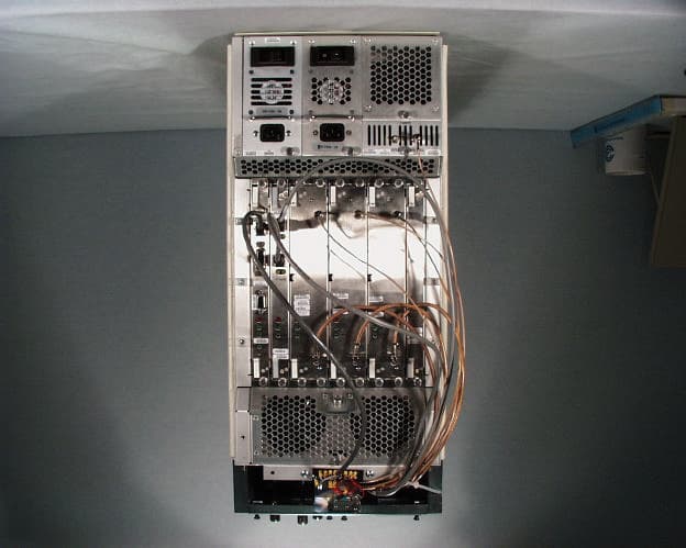
Click to zoom
Application Details
- Equipment Class
- PCB - PCS Licensed Transmitter
- Date of Grant
- Dec 21, 2000
- Application Purpose
- Original Equipment
- Date of Application
- Dec 21, 2000
- Equipment Note
- TurboMax Base Station
- Frequency Range
- 1934.20000000 - 1985.20000000
- Company
- ADC Telecommunications Inc.
- Country
- United States
Documents & Files
Document Text
Text extracted from the exhibit documents filed with the FCC. Open a document above to read the original.
Users Manual
Application Note 16 – version 1.1 page 1 pplication Note A TurboMAX BTS Installing and Configuring Application Note AN – 16 Date December 13, 2000 Products Covered TurboMAX Applicable System Release 5.0 Subject TurboMAX Application Note Intended Audience Network Planners, Installers, and End Users Number of pages 15 1.1 Objective The TurboMAX BTS is being introduced as part of System Release 5.0. This document describes the TurboMAX, and gives instructions on how to install and configure it. 1.2 Audience Network Planners, Installers, and End Users. 1.3 Scope This document is applicable to System Release 5.0. Application Note 16 – version 1.1 page 2 pplication Note A 2 Description The interWAVE TurboMAX is a high-power, low-cost, compact BTS used to provide WLL (Wireless Local Loop), microcell expansion, and specialty GSM deployment. It complies with all relevant GSM specifications related to Abis and Air (Um) Interfaces, so it can be used with any other GSM-compliant BSCs and mobile stations. The TurboMAX is 25” (63.50 cm) tall, 11” (27.94 cm) wide, and 19” (48.26 cm) deep. The TurboMAX consists of a chassis, one IWP card, one E1 or T1 Trunk card, two or three TRXs, an EEPROM RFD card, one Main Power Supply module, one Amplifier Power Supply module, one Clock module, two Fan modules, a high-power Amplifier module, and a CMA (Cable Management Assembly), which contains combiners, diplexers, and/or filters, and which routes external cabling into the TurboMAX chassis. Figure 1 shows the front view of a fully-loaded TurboMAX. Figure 1. Typical Fully-Loaded TurboMAX Application Note 16 – version 1.1 page 3 pplication Note A 3 Installation 3.1 Mounting the Chassis 1) Mount the TurboMAX chassis as you would any other interWAVE chassis, either in an equipment rack, on a wall, or on a table, as described in the WAVEXpress BTS Installation and Commissioning Guide. 3.2 Verifying and Configuring the E1 or T1 Card 2) When your TurboMAX is equipped with an E1 Trunk card, verify that the trunk impedance is set correctly on the eight-position DIP switch on the edge of the E1 card. For 75 Ohm coaxial cable, DIP switches 1, 2, 3, 5, 6, and 7 must be set to ON, and DIP switches 4 and 8 must be set to OFF, as indicated on the DIP switch housing. For 120 Ohm twisted pair, all the DIP switches must be set to ON. If you have set the E1 Trunk card for 75 Ohm coaxial cable, you may also need to ground the E1 coaxial cable shields. Note that only one side of the coaxial cables should be grounded to avoid ground loops. To ground the Port 0 Transmit shield, place a jumper across P9 pins 1 and 2. To ground the Port 0 Receive shield, place a jumper across P8 pins 1 and 2. To ground the Port 1 Transmit shield, place a jumper across P10 pins 1 and 2. To ground the Port 1 Receive shield, place a jumper across P11 pins 1 and 2. 3) When your TurboMAX is equipped with a T1 Trunk card, configure the trunk for the cable distance to the DSX1 T1 demarcation point using the eight-position DIP switch on the edge of the T1 card. For Port 0, use DIP switch pins 1 – 4, and for Port 1, use DIP switch pins 4 – 8. For Port 0, when the TurboMAX is connected directly to another WAVEXpress chassis or if it is connected to a T1 DSX1 demarcation point at 0-133ft (0-40m), set DIP switch 1 to OFF, and set DIP switches 2, 3, and 4 to ON, as indicated on the DIP switch housing. When the TurboMAX is connected to a T1 DSX1 demarcation point at 133-266ft (40-80m), set DIP switches 1 and 2 to OFF, and set DIP switches 3 and 4 to ON. When the TurboMAX is connected to a T1 DSX1 demarcation point at 266-399ft (80-120m), set DIP switches 1 and 3 to OFF, and set DIP switches 2 and 4 to ON. When the TurboMAX is connected to a T1 DSX1 demarcation point at 399-533ft (120-160m), set DIP switches 1, 2, and 3 to OFF, and set DIP switch 4 to ON. When the TurboMAX is connected to a T1 DSX1 demarcation point at 533-655ft (160-200m), set DIP switches 1 and 4 to OFF, and set DIP switches 2 and 3 to ON. For Port 1, when the TurboMAX is connected directly to another WAVEXpress chassis or if it is connected to a T1 DSX1 demarcation point at 0-133ft (0-40m), set DIP switch 5 to OFF, and set DIP switches 6, 7, and 8 to ON, as indicated on the DIP switch housing. When the TurboMAX is connected to a T1 DSX1 demarcation point at 133-266ft (40-80m), set DIP switches 5 and 6 to OFF, and set DIP switches 7 and 8 to ON. When the TurboMAX is connected to a T1 DSX1 demarcation point at 266-399ft (80-120m), set DIP switches 5 and 7 to OFF, and set DIP switches 6 and 8 to ON. When the TurboMAX is connected to a T1 DSX1 demarcation point at 399-533ft (120-160m), set DIP switches 5, 6, and 7 to OFF, and set DIP switch 8 to ON. When the TurboMAX is connected to a T1 DSX1 demarcation point at 533-655ft (160-200m), set DIP switches 5 and 8 to OFF, and set DIP switches 6 and 7 to ON. Application Note 16 – version 1.1 page 4 pplication Note A 3.3 Verifying the Internal Cabling 4) Verify that the clock, antenna, and the other RF cable ends are correctly tightened to 7 to 10 in. lbs. (79 to 113N.cm). 5) Verify the cable from the IWP card ENET connector to the external alarm terminal block on the front of the TurboMAX chassis. Application Note 16 – version 1.1 page 5 pplication Note A 3.4 Connecting External Cabling 6) Connect the E1 or T1 cabling directly to the E1 or T1 card using individually-shielded twisted-pair cables, using the standard RJ-48C pinout. The RJ-48C pinout is as follows: Pin 1 – Receive Ring/Shield; Pin 2 – Receive Tip; Pin 4 – Transmit Ring/Shield; Pin 2 – Transmit Tip. When you are connecting the TurboMAX directly to another TurboMAX or another piece of equipment via an E1 or T1 port, make sure you use a crossover cable that connects the Receive leads to the Transmit leads. 7) The TurboMAX comes in two configurations: low-power, with a single antenna, or high-power, with up to three antennas. When you are adding an antenna to a low-power TurboMAX, connect the antenna …
Text truncated - open the document above for the full version.
Cover Letter(s)
COMMUNICATION CERTIFICATION LABORATORY TEST REPORT: 73-7341 FCC ID: OEW-M64-25 Page 86 of 87 Exhibit 13 Exhibit 13: Cover Letters December 18, 2000 FEDERAL COMMUNICATIONS COMMISSION Equipment Authorization Division 7435 Oakland Mills Road Columbia, MD 21046 To Whom It May Concern: Enclosed is the documentation for a licensed PCS base station transmitter operating under FCC Part 24. This application was certified by Communication Certification Laboratory (CCL) under the TCB (Scope B1) program. The applicant, model number and FCC ID are listed below: Applicant: interWAVE Communications, Inc. Model: M64 FCC ID: OEW-M64-25 Please let me know if I can be of further assistance. Sincerely yours, COMMUNICATION CERTIFICATION LABORATORY Joseph W. Jackson V.P. Marketing COMMUNICATION CERTIFICATION LABORATORY TEST REPORT: 73-7341 FCC ID: OEW-M64-25 Page 87 of 87 Exhibit 13 Request for Confidentiality
External Photos
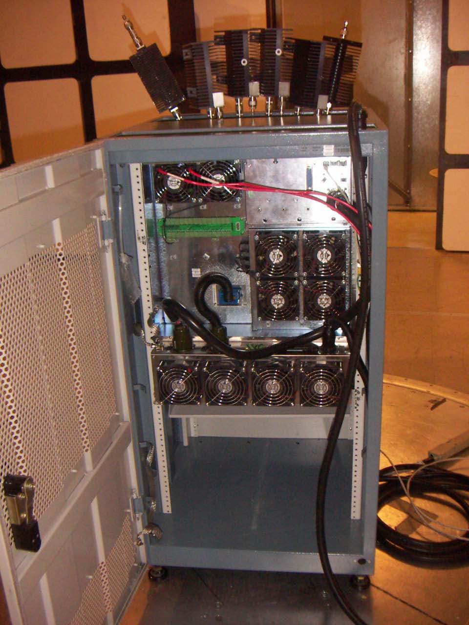
COMMUNICATION CERTIFICATION LABORATORY TEST REPORT: 73-7341 FCC ID: OEW-M64-25 Page 4 of 87 Exhibit 3 Exhibit 3: Photographs of Overall Appearance Front View of the M64 COMMUNICATION CERTIFICATION LABORATORY TEST REPORT: 73-7341 FCC ID: OEW-M64-25 Page 5 of 87 Exhibit 3 Back View of the M64
ID Label/Location Info
COMMUNICATION CERTIFICATION LABORATORY TEST REPORT: 73-7341 FCC ID: OEW-M64-25 Page 1 of 87 Exhibit 1 Exhibit 1: FCC ID Label Equipment Identification Label In accordance with the requirements of Sections 2.925 and 2.926 of the FCC Rules, the following information will be permanently affixed to the interWAVE Communications, Inc. Model M64 as shown in the sketch below. COMMUNICATION CERTIFICATION LABORATORY TEST REPORT: 73-7341 FCC ID: OEW-M64-25 Page 2 of 87 Exhibit 1 Sketch showing the label placement.
Internal Photos
COMMUNICATION CERTIFICATION LABORATORY TEST REPORT: 73-7341 FCC ID: OEW-M64-25 Page 71 of 87 Exhibit 9 Exhibit 9: Internal Photographs Front view of the Processor board COMMUNICATION CERTIFICATION LABORATORY TEST REPORT: 73-7341 FCC ID: OEW-M64-25 Page 72 of 87 Exhibit 9 Side view of the Processor board COMMUNICATION CERTIFICATION LABORATORY TEST REPORT: 73-7341 FCC ID: OEW-M64-25 Page 73 of 87 Exhibit 9 Front view of the E1/T1 Interface board COMMUNICATION CERTIFICATION LABORATORY TEST REPORT: 73-7341 FCC ID: OEW-M64-25 Page 74 of 87 Exhibit 9 Side view of the E1/T1 Interface board COMMUNICATION CERTIFICATION LABORATORY TEST REPORT: 73-7341 FCC ID: OEW-M64-25 Page 75 of 87 Exhibit 9 Front view of the TRX Module (#1) COMMUNICATION CERTIFICATION LABORATORY TEST REPORT: 73-7341 FCC ID: OEW-M64-25 Page 76 of 87 Exhibit 9 Side view of the TRX Module (#1) COMMUNICATION CERTIFICATION LABORATORY TEST REPORT: 73-7341 FCC ID: OEW-M64-25 Page 77 of 87 Exhibit 9 Front view of the TRX Module (#2) COMMUNICATION CERTIFICATION LABORATORY TEST REPORT: 73-7341 FCC ID: OEW-M64-25 Page 78 of 87 Exhibit 9 Side view of the TRX Module (#2) COMMUNICATION CERTIFICATION LABORATORY TEST REPORT: 73-7341 FCC ID: OEW-M64-25 Page 79 of 87 Exhibit 9 Front view of the RF Distribution Module COMMUNICATION CERTIFICATION LABORATORY TEST REPORT: 73-7341 FCC ID: OEW-M64-25 Page 80 of 87 Exhibit 9 Side view of the RF Distribution Module COMMUNICATION CERTIFICATION LABORATORY TEST REPORT: 73-7341 FCC ID: OEW-M64-25 Page 81 of 87 Exhibit 9 120 VAC Power Supply COMMUNICATION CERTIFICATION LABORATORY TEST REPORT: 73-7341 FCC ID: OEW-M64-25 Page 82 of 87 Exhibit 9 100-240 VAC Power Supply
RF Exposure Info
COMMUNICATION CERTIFICATION LABORATORY TEST REPORT: 73-7341 FCC ID: OEW-M64-25 Page 84 of 87 Exhibit 11 Exhibit 11: RF Exposure/Environmental Evaluation Section 24.51 and 24.52 Requirement 24.51: The device must comply with IEEE C.95.1-1991, (ANSI/IEEE C.95.1-1992), “Safety Levels with Respect to Human Exposure to Radio Frequency Electromagnetic Fields, 3 kHz to 300 GHz”. Measurement methods are specified in IEEE C95.3-1991, “Recommended Practice for the Measurement of Potentially Hazardous Electromagnetic Fields-RF and Microwave”. Requirement 24.52: Licensees and manufacturers are subject to the radio frequency radiation exposure requirements specified in § 1.1307(b), 2.1091 and 2.1093 of this chapter, as appropriate. All equipment shall be considered to operate in a “general population/uncontrolled” environment. Applications for equipment authorization of devices operating under this section must contain a statement confirming compliance with these requirements for both fundamental emissions and unwanted emissions. Technical information showing the basis for this statement must be submitted to the Commission upon request. Demonstration of Compliance: The M64 is classified as a mobile device, which is installed so that a minimum separation distance of 20 centimeters is maintained between the transmitter’s radiating structure and the body of the user or nearby persons and compliance to RF exposure is performed during the licensing of this device. Therefore, the M64 is categorically excluded from routine environmental evaluation for RF exposure prior to certification.
Test Report
COMMUNICATION CERTIFICATION LABORATORY TEST REPORT: 73-7341 FCC ID: OEW-M64-25 Page 8 of 87 Exhibit 6 Exhibit 6: Test Report TEST REPORT FROM: COMMUNICATION CERTIFICATION LABORATORY 1940 W. Alexander Street Salt Lake City, Utah 84119-2039 Type of Report: Certification TEST OF: M64 FCC ID: OEW-M64-25 To Part 24 Subpart E and Part 2 Subpart J of the FCC Rules and Regulations Test Report Serial No: 73-7341 Applicant: interWAVE Communications, Inc. 312 Constitution Drive Menlo Park, CA, 94025 Date(s) of Test: November 1 - 3, 2000 Issue Date: December 18, 2000 Equipment Receipt Date: November 1, 2000 COMMUNICATION CERTIFICATION LABORATORY TEST REPORT: 73-7341 FCC ID: OEW-M64-25 Page 9 of 87 Exhibit 6 CERTIFICATION OF ENGINEERING REPORT This report has been prepared by Communication Certification Laboratory to determine compliance of the device described below with the notification requirements of FCC Part 24, Subpart E. This report may be reproduced in full, partial reproduction may only be made with the written consent of the laboratory. The results in this report apply only to the sample tested. - Applicant: interWAVE Communications, Inc. - Manufacturer: interWAVE Communications, Inc. - Brand Name: TurboMax - Model Number: M64 - FCC ID: OEW-M64-25 On this 18 th day of December 2000, I, individually, and for Communication Certification Laboratory, certify that the statements made in this engineering report are true, complete, and correct to the best of my knowledge, and are made in good faith. Although NVLAP has recognized that the Communication Certification Laboratory EMC testing facilities are in good standing, NVLAP does not endorse the product described in this report. COMMUNICATION CERTIFICATION LABORATORY Checked by: William S. Hurst, P.E. Vice President Tested by: Roger J. Midgley EMC Engineering Manager COMMUNICATION CERTIFICATION LABORATORY TEST REPORT: 73-7341 FCC ID: OEW-M64-25 Page 10 of 87 Exhibit 6 SECTION 1.0 CLIENT INFORMATION 1.1 Client Information: Company Name: interWAVE Communications, Inc. 312 Constitution Drive Menlo Park, CA, 94025 Contact Name: Roderick E. Thorne Title: Vice President, Quality and Compliance COMMUNICATION CERTIFICATION LABORATORY TEST REPORT: 73-7341 FCC ID: OEW-M64-25 Page 11 of 87 Exhibit 6 SECTION 2.0 EQUIPMENT UNDER TEST (EUT) 2.1 Identification of EUT: Trade Name: TurboMax Model Name or Number: M64 Serial Number: N/A Options Fitted: N/A Country of Manufacture: U.S.A. 2.2 Description of EUT: The TurboMax Series M64 product family consists of a system of cards performing various functions which plug into the M64 chassis backplane and cabinet to create a number of specific product configurations, each designated by a particular model number. This document describes the configurations for the PCS1900 MHz Base Transceiver System (BTS) used for wireless mobile telephony employing the GSM radio interface protocol. M64 Series 1900MHz Base Transceiver Station (BTS) The functions of the BTS are defined in the system of ETSI specifications for the GSM wireless telephone system. Its basic role is to communicate with wireless mobile telephone hand sets over the radio interface and to establish a terrestial land-line link to the BSC for system control functions and for eventual connection of the mobile traffic to the public telephone network. There are four model numbers for the M64 Series 1900MHz BTS as follows: M640323 3-TRX’s into a 3-way combiner driving one antenna, 8-Watt. M640341 2-TRX’s into a 2-way combiner driving one antenna, 12-Watt M640326 3-TRX’s without a combiner, each driving a separate antenna, 25-Watt M640329 2-TRX’s without a combiner, each driving a separate antenna, 25-Watt 2.3 Modification Incorporated/Special Accessories on EUT: There were no modifications or special accessories required to comply with the specification. COMMUNICATION CERTIFICATION LABORATORY TEST REPORT: 73-7341 FCC ID: OEW-M64-25 Page 12 of 87 Exhibit 6 SECTION 3.0 TEST SPECIFICATION, METHODS & PROCEDURES 3.1 Test Specification: Title: FCC PART 24, Subpart E (47 CFR 24). Broadband Personal Communications Services (PCS) Purpose of Test: The tests were performed to demonstrate Initial compliance. 3.2 Methods & Procedures (Applicable to the M64): § 24.51 (d) RF Hazard - (SAR) Applicants for type acceptance of transmitters that operate in these service must determine that the equipment complies with IEEE C95.1-1991 (ANSI/IEEE C95.1-1992), “Safety Levels with Respect to Human Exposure to Radio Frequency Electromagnetic Fields, 3 kHz to 200 GHz.” (SAR) Measurement methods are specified in IEEE C95.3-1991, “Recommended Practice for the Measurement of Potentially Hazardous Electromagnetic Fields - RF and Microwave.” § 2.1046 RF Power Output - § 24.232 § 2.1046 (a) For transmitters other than single sideband, independent sideband and controlled carrier radiotelephone, power output shall be measured at the RF output terminals when the transmitter is adjusted in accordance with the tune-up procedure to give the values of current and voltage on the circuit elements specified in § 2.983 (d)(5). § 24.232 (a) Base Stations are limited to 1640 watts peak equivalent isotropically radiated power (e.i.r.p.) with an antenna height up to 300 meters HAAT. In no case may the peak output power of a base station transmitter exceed 100 watts. (b) Mobile/portable stations are limited to 2 watts e.i.r.p. peak power and the equipment must employ means to limit COMMUNICATION CERTIFICATION LABORATORY TEST REPORT: 73-7341 FCC ID: OEW-M64-25 Page 13 of 87 Exhibit 6 the power to the minimum necessary for successful communications. § 2.1047 Modulation Characteristics The M64 uses digital modulation; therefore, this section does not apply. § 2.1049 Occupied Bandwidth § 2.1049 The occupied bandwidth, that is the frequency bandwidth such that, below its lower and above its upper frequency limits, the mean powers radiated are each equal to 0.5 percent of the total mean power radiated by a given emission s…
Text truncated - open the document above for the full version.
Test Setup Photos
COMMUNICATION CERTIFICATION LABORATORY TEST REPORT: 73-7341 FCC ID: OEW-M64-25 Page 68 of 87 Exhibit 7 Exhibit 7: Test Set-Up Photographs Front view of worst case radiated and line conducted emissions COMMUNICATION CERTIFICATION LABORATORY TEST REPORT: 73-7341 FCC ID: OEW-M64-25 Page 69 of 87 Exhibit 7 Back view of worst case radiated and line conducted emissions
Contact Information
Applicant
Mark Miska(Director of Technology)
Technical Contact
Communication Certification LaboraotyScott B Earl
[email protected]801-972-6146
1940 W. Alexander Street · Salt Lake City, Utah · United States
Test Firm
Communication Certification Lab.Scott Earl
Technical Specifications
| # | Rule Parts | Frequency Range | Power Output | Emission | Tolerance |
|---|---|---|---|---|---|
| 3 | 24E | 1.93 GHz - 1.99 GHz | 8.13 W | 312KW7E | 10 ppm |
Other Applications from ADC Telecommunications Inc.
OEWAKAD19
Oct 30, 2006GSM Base Station
Equipment Class
PCB - PCS Licensed Transmitter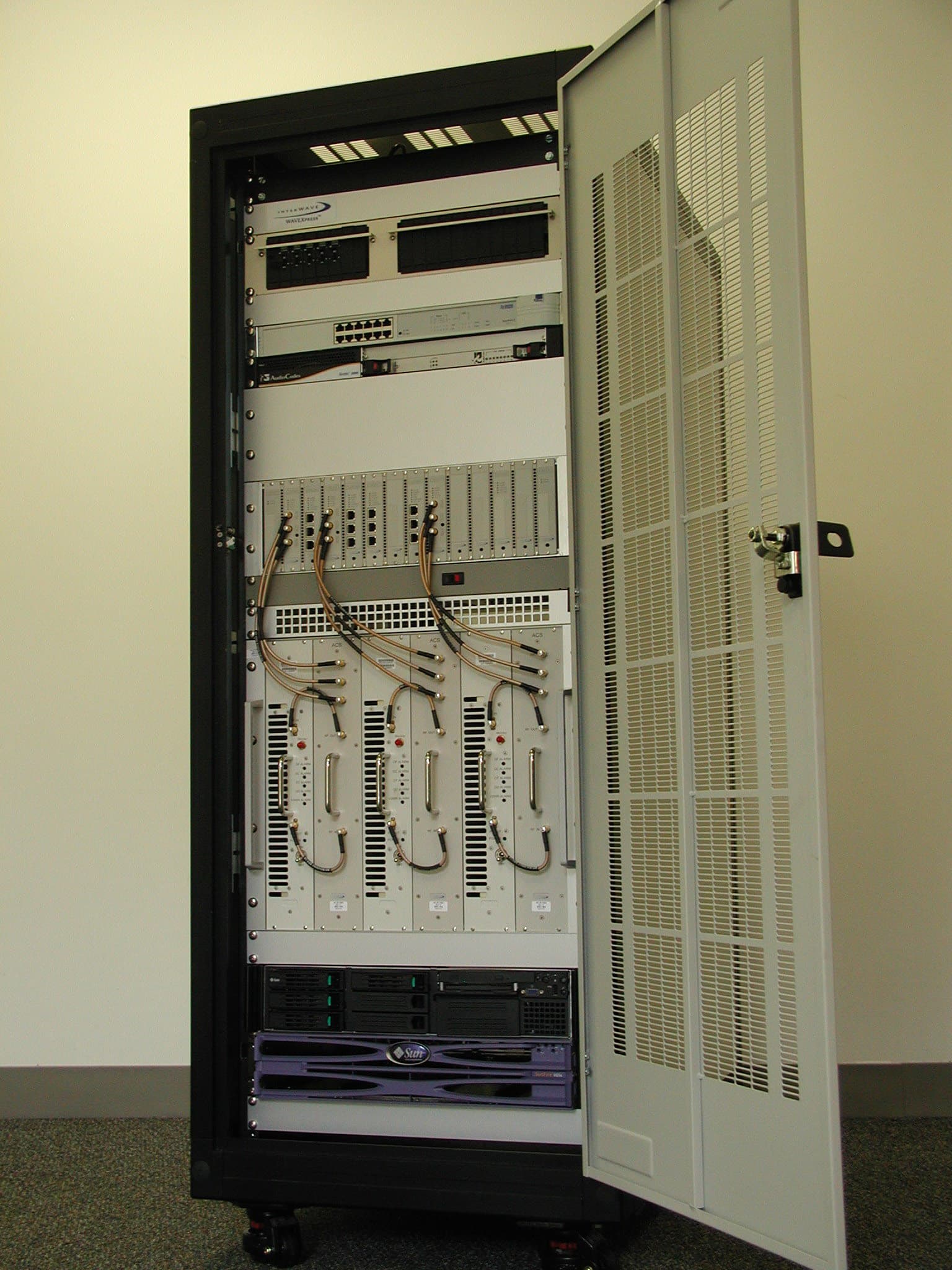
OEW-AGBB-M1
Dec 30, 2004CDMA Cellular BaseStation
Equipment Class
PCB - PCS Licensed Transmitter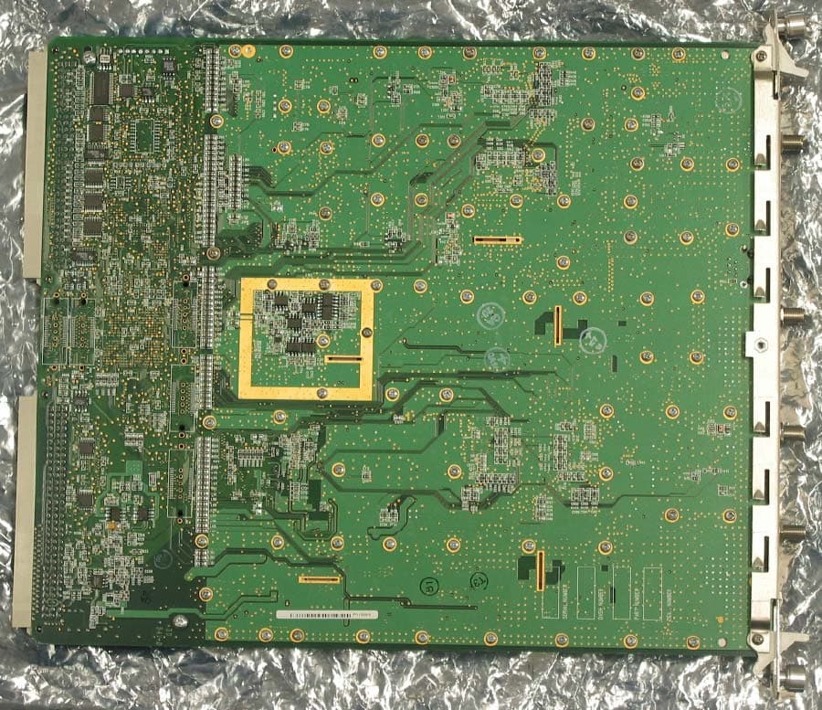
OEWAUAC85
Mar 03, 2003Ultra WAVE BTS
Equipment Class
TNB - Licensed Non-Broadcast Station Transmitter
OEW-AGBB
Feb 04, 2003CDMA2000 Wireless Basestation
Equipment Class
AMP - Amplifier
OEWCX-DS3-53G
Jul 25, 2002Point to Point DSX3 / IP Transceiver
Equipment Class
NII - Unlicensed National Information Infrastructure TX