OF2FWBASE15PCSfixed wireless base station
AT&T Wireless Services, Inc.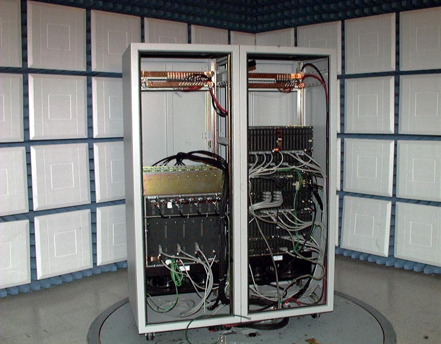
Click to zoom
Application Details
- Equipment Class
- PCB - PCS Licensed Transmitter
- Date of Grant
- Dec 06, 2001
- Application Purpose
- Original Equipment
- Date of Application
- Jun 27, 2001
- Equipment Note
- fixed wireless base station
- Frequency Range
- 1946.00000000 - 1949.00000000
- Company
- AT&T Wireless Services, Inc.
- Country
- United States
Documents & Files
Document Text
Text extracted from the exhibit documents filed with the FCC. Open a document above to read the original.
Users Manual
Chapter 13:Users Manuals AT&T Wireless Group13-1 FCC Type Acceptance Application 11333 Rev. 1.0 6/18/01 Chapter 13Users Manuals A user manual has not been included within this Type Approval. This product is delivered, installed, and maintained by AT&T and/or authorized personal. Base FCC Regulatory Test Report 13-2AT&T Wireless Group FCC Type Acceptance Application 11333 Rev. 1.0 6/18/01
Attestation Statements
Chapter 1:Attestation Statements AT&T Wireless Group1-1 FCC Type Acceptance Application 11333 Rev. 1.0 6/19/01 Chapter 1Attestation Statements Base FCC Regulatory Test Report 1-2AT&T Wireless Group FCC Type Acceptance Application 11333 Rev. 1.0 6/19/01 AT&T Wireless Services Wireless Local Technologies Group PO Box 97059 Redmond. W 98073-9759 425-702-2500 June 15, 2001 Federal Communications Commission Attn.: Product Type Approval Department 7435 Oakland Mills Rd. Columbia MD 21046 To Whom It May Concern: The AT&T Wireless Service Base Station, B1.5 PCS, has been tested in accordance with the requirements con- tained in the appropriate Commission regulations. To the best of our knowledge, these tests were performed using measurement procedures consistent with industry or Commission standards and demonstrate that the equipment complies with the appropriate standards. Each unit manufactured, imported or marketed as defined in the Commission's regulations, will conform to the sample(s) tested within the variation that can be expected due to the quantity produced and testing on a statistical basis. The test results and conclusions accompanied with this Type Acceptance Application and test report are certified to be true and correct, having been taken personally or under the supervision of the undersigned individuals.
Cover Letter(s)
Chapter 3:Cover Letters AT&T Wireless Group3-1 FCC Type Acceptance Application 11333 Rev. 1.0 6/18/01 Chapter 3Cover Letters Overview This section describes functional product interaction with other products pending FCC approval. Contents 3.1PWAN Base Station—System Dependent Products . . . . . . . . . . . . . 3-2 Base FCC Regulatory Test Report 3-2AT&T Wireless Group FCC Type Acceptance Application 11333 Rev. 1.0 6/18/01 3.1PWAN Base Station—System Dependent Products This unit, the PWAN Base, comprises the second half of the PWAN System. Currently the Remote Unit has been tested and is undergoing FCC evaluation for Type Approval. The Remote Unit is located at remote residences and, in concert with the PWAN Base, completes the PWAN System. This PWAN Base Type Approval is for a Class A commercial product that will function in concert with the aforementioned Remote Unit to complete the PWAN System, providing wireless loop service. This system operates in the PCS spectrum Band D and can communicate with the follwing three products: • Remote Unit, FCC ID OF2CLRUDD3AXX • Remote Unit 2, FCC ID OF2CLRUDD3AXX • Remote Unit 3, FCC ID OF2PCSR30
Cover Letter(s)
AT&T Wireless Services, Inc. 1150 Connecticut Avenue, N.W. 4 th Floor Washington DC 20036 (202) 223-9222 Fax (202) 223-9095 June 28, 2001 Richard Fabina, Chief Equipment and Authorization Branch Office of Engineering and Technology Federal Communications Commission Washington DC 20554 In re: AT&T Wireless Services, Inc. Equipment Authorization OF2FWBASE15PCS Confirmation Number EA101516 Request for Confidential Treatment of Exhibits Dear Mr. Fabina: Pursuant to the provisions of Sections 0.459(a) and (b), AT&T Wireless Services, Inc. (“AWS”) respectfully requests confidential treatment pursuant to Section 0.457(d) of the following Exhibits in the above-referenced Equipment Authorization Grant: Exhibit DescriptionExhibit Section Block DiagramChapter 2 Internal PhotosChapter 6 Operational DescriptionChapter 7 Parts List Tune Up InformationChapter 8 Schematic Dia gramsChapter 10 Each of the foregoing exhibits constitute trade secrets and commerical information relating to the Equipment Authorization that AWS would not normally make publicly available. Disclosure of such information could provide competitors of AWS with information that would put AWS at a competitive disadvantage in the market place. AWS inadvertently included the foregoing exhibits in its originally-filed Equipment Authorization application without requesting confidential treatment. Though the information has been made public ly available over the Commission’s web site, AWS Mr. Richard Fabina June 28, 2001 Page Two requests confidential treatment for these exhibits on a going forward basis to reduce the competitive disadvantage it will suffer by disclosure of the exhibits in question. For the foregoing reasons, AT&T Wireless Services, Inc. requests confidential treatment for the exhibits and requests that they be removed from the above-referenced application at the earliest possible time. Respectfully submitted, AT&T Wireless Services, Inc. ___________________________________ David C. Jatlow Vice President, Federal Regulatory Affairs
Cover Letter(s)
AT&T Wireless Ser vices, Inc. OF2FWBASE15PCS EA101516 Correspondence 21085 The following is in response to clarifications requested by the FCC in Correspondence 21085. The responses of AT&T Wireless Services, Inc. listed in bold. 1. Power output listed on FCC form 731 will be changed to 2.5 W corresponding to the average power measured in section 11.2.7.2. This is acceptable. 2. Please specify the lowest and highest channel center frequency that allows compliance with the band edge attenuation limits. The lowest and highest frequencies are 1946 and 1949 MHz. 3. Test results for radiated spurious emissions should be presented in terms of dBc to satisfy section 24.238 requirement of 43+10log (P). Also, test procedure should be the substitution method. Please submit revised results. This testing is presented within the Part 15 radiated data. The Class A Part 15 limit line above 1 GHz is 500 uV/m or 20log[(500x10 -6 ) / (1x10 -6 )] = 59 dBuV. The highest amplitude allowed by Part 24 is -13dBm, i.e. 43+10log(2.5 W)=47, +34 - 47= - 13dBm/1MHz. This translates into 94 dBuV.......Therefore, the Part 15 data ( above 1GHz) shows mostly noise floor with everything below the 59 dBuV limit line.......which is 35 dBuV MORE stringent than the Part 24 requirement. Because this product measured so far below the limit (both part 24 and part 15), we used the data for both. Please contact Keith Peavler if further information is required. Thank you for your time and effort.
External Photos
Chapter 4:External Photographs AT&T Wireless Group4-1 FCC Type Acceptance Application 11333 Rev. 1.0 6/18/01 Chapter 4External Photographs Overview This section contains external photographs of the PWAN Base Station. Contents 4.1External Photographs . . . . . . . . . . . . . . . . . . . . . . . . . . . . . . . . . . . . 4-2 4.2Internal Photographs . . . . . . . . . . . . . . . . . . . . . . . . . . . . . . . . . . . . . 4-3 Base FCC Regulatory Test Report 4-2AT&T Wireless Group FCC Type Acceptance Application 11333 Rev. 1.0 6/18/01 4.1External Photographs The front view of the PWAN Base Station shows internal access via double doors. The double cabinet may be separated for various installation considerations with independent casters for additional mobility. Figure 4.1Front corner view of the PWAN Base Station Chapter 4:External Photographs AT&T Wireless Group4-3 FCC Type Acceptance Application 11333 Rev. 1.0 6/18/01 4.2Internal Photographs The PWAN Base Station separates digital functionality to the left and the RF functionalities to the right for separation at various installations. Each cabinet is independently powered with circuit breaker protection and air-moving devices. Figure 4.2Open doors rear view of PWAN Base Station Base FCC Regulatory Test Report 4-4AT&T Wireless Group FCC Type Acceptance Application 11333 Rev. 1.0 6/18/01 Figure 4.3Front view of PWAN Base Cabinet - doors open
ID Label/Location Info
Chapter 5:ID Label/Location Information AT&T Wireless Group5-1 FCC Type Acceptance Application 11333 Rev. 1.0 6/18/01 Chapter 5ID Label/Location Information Overview This section contains FCC labelling information and location for the PWAN Base. Contents 5.1ID Label . . . . . . . . . . . . . . . . . . . . . . . . . . . . . . . . . . . . . . . . . . . . . . 5-2 5.2Location Information . . . . . . . . . . . . . . . . . . . . . . . . . . . . . . . . . . . . 5-3 Base FCC Regulatory Test Report 5-2AT&T Wireless Group FCC Type Acceptance Application 11333 Rev. 1.0 6/18/01 5.1ID Label Figure 5.1Example FCC ID Label Chapter 5:ID Label/Location Information AT&T Wireless Group5-3 FCC Type Acceptance Application 11333 Rev. 1.0 6/18/01 5.2Location Information Figure 5.2FCC Compliance Label—Possible exterior location Base FCC Regulatory Test Report 5-4AT&T Wireless Group FCC Type Acceptance Application 11333 Rev. 1.0 6/18/01
RF Exposure Info
Chapter 9:RF Exposure Information AT&T Wireless Group9-1 FCC Type Acceptance Application 11333 Rev. 1.0 6/18/01 Chapter 9RF Exposure Information Overview This chapter contains information as to how the product was determined compliant with FCC Part 24 subsection 24.51 Contents 9.1RF Human Exposure - FDTD Analysis and SAR Testing . . . . . . . . 9-2 Base FCC Regulatory Test Report 9-2AT&T Wireless Group FCC Type Acceptance Application 11333 Rev. 1.0 6/18/01 9.1RF Human Exposure - FDTD Analysis and SAR Testing 9.1.1Applicable FCC Rules FCC Subpart 24.51 - Applications for Type Approval of transmitters operating within the PCS region must determine that the equipment complies with IEEE C95.1-1991, “IEEE Standards for Safety Levels with Respect to Human Exposure to Radio Frequency Electromagnetic Fields, 3 kHz to 300 GHz” as measured using methods specified in IEEE C95.3 - 1991, “Recommended Practice for the Measurement of Potentially Hazardous Electromagnetic Fields - RF and Microwave.” 9.1.2Typical Test Configuration This MPE analysis was completed for a worse case situation, with a typical roof top antenna (six feet high) PWAN Base Station installation. Characteristics used for this typical MPE are shown in Table 9.1. Each PWAN Base Station installed will include an MPE analysis with data and required paperwork being stored and filed with the FCC as per regulatory requirements. 9.1.3Typical MPE Test Results The PWAN Base Station meets the required FCC regulatory part 24 requirements as shown in the following figures. Figure 9.1 illustrates horizontal distance versus power density, while Figure 9.2 provides graphical data of horizontal distance versus uncontrolled MPE. As shown in Table 9.2, a typical PWAN Base installation meets FCC MPE requirements. Per regulations, all installations will include an MPE analysis with data being stored and filed appropriately. Chapter 9:RF Exposure Information AT&T Wireless Group9-3 FCC Type Acceptance Application 11333 Rev. 1.0 6/18/01 Figure 9.1Power Density vs. Horizontal Distance Figure 9.2Uncontrolled MPE vs. Horizontal Distance 0.01 0.1 1 10 100 1000 10000 0.1110100100010000 Horizontal Distance from Antenna, ft Power Density, w/cm 2 100% of Controlled Limit 100 % of Uncontrolled FCC Limit 5 % of Uncontrolled FCC Limit 20 cm (.656 ft) Predicted Power Density 0.001 0.01 0.1 1 10 100 1000 0.1110100100010000 Horizontal Distance From Antenna, ft % Uncontrolled MPE 100% of Controlled Limit 100% of Uncontrolled MPE 5 % of Uncontrolled MPE 20 cm (0.656 ft) Predicted Power Density Base FCC Regulatory Test Report 9-4AT&T Wireless Group FCC Type Acceptance Application 11333 Rev. 1.0 6/18/01 Figure 9.3Initial Values used for MPE unitsValue FrequencyMHz1945.5 # of Channels#18 Max ERP/ChWatts2.047 Max Pwr/Ch Into Ant.Watts0.091 BS Height (Center of Radiator)feet6 Calculation Point feet6 (above ground or roof surface) Antenna Model No.FR-16-00-P Max Ant GaindBd13.5 Down tiltdegrees0 Miscellaneous Att.dB0 Height of aperturefeet4 Ant H -Plane 3 dB Beamwidth degrees90 Distance to Ant bottom feet-2 WOS? Y/N?n
Test Report
Chapter 11:Test Report AT&T Wireless Group11-1 FCC Type Acceptance Application 11333 Rev. 1.0 6/19/01 Chapter 11Test Report Overview This section includes the test report and data showing compliance with all applicable technical standards. Contents 11.1Test Methodology . . . . . . . . . . . . . . . . . . . . . . . . . . . . . . . . . . . . . . 11-2 11.2RF Characterization Test Results . . . . . . . . . . . . . . . . . . . . . . . . . 11-31 11.3Electromagnetic Compatibility Test Results. . . . . . . . . . . . . . . . . 11-65 Base FCC Regulatory Test Report 11-2AT&T Wireless Group FCC Type Acceptance Application 11333 Rev. 1.0 6/19/01 11.1 Test Methodology This section describes the test methodology used to validate the performance of the AT&T Wireless Services PWAN Base Station against the applicable requirements of FCC Part 2, 15, and Part 24. 11.1.1 Introduction The purpose of this chapter is to present the test methodology used to verify FCC regulatory compliance of the PWAN Base Station. Throughout this document, all depictions of test configurations utilize a common set of interfaces. These interfaces are described in detail in Chapter 7, “Operational Description” of this document. The name and purpose of each interface is summarized inTable 11.1 below: Table 11.1 PWAN Interface Definitions 11.1.2 Base Station Frequency Stability vs. Temperature 11.1.2.1 Applicable FCC Rules Parts FCC Subpart 2.995 - Measured over the temperature range of -30 to +50 C. Frequency measurements shall be made at the extremes and at intervals of not greater than 10 degrees C throughout the range. Only the frequency determining portions of the transmitter need be subjected to this test. FCC Subpart 24.236 - The frequency stability shall be sufficient to ensure that the fundamental emission stays within the authorized frequency block. Interface IDDescription T InterfaceTerminal interface to Remote Units A InterfaceAir interface between Remote Units and Base Station radio equipment P InterfaceInterface between Base Station radio equipment and Base Station control Csw InterfaceInterface that provides public switched telephone network (PSTN) connectivity for call processing Chapter 11:Test Report AT&T Wireless Group11-3 FCC Type Acceptance Application 11333 Rev. 1.0 6/19/01 11.1.2.2 Overview The PWAN Base Station obtains its frequency stability from GPS- disciplined 10 MHz ovenized oscillators located on the station’s primary and redundant Synchronization Cards. Either Synchronization Card is capable of functioning in one of the following three operational modes: Oscillator operating in GPS Locked Mode: During normal operation, the frequency of the 10 MHz oscillator is disciplined by GPS to an accuracy of approximately 0.005 PPM. Oscillator operating in GPS Holdover Mode: In the event that GPS signals are lost (due to an antenna or GPS receiver failure), the 10 MHz oscillator will utilize the most current correction data obtained from the on-board GPS receiver to maintain an accuracy of approximately 0.02 PPM over a 24 hour period. Oscillator operating in GPS Free-Run mode: In the event that GPS is completely unobtainable, the 10 MHz oscillator will free-run with an accuracy of approximately. 0.2 PPM. The 10 MHz disciplined oscillators on the primary and redundant Synchronization Cards serve as the main frequency-determining element in the Base Station. Any frequency error present in the 10 MHz output of the Synchronization Cards will create a corresponding frequency error in each transmitted OFDM tone at the Base Station operating frequency. The Base Station also contains its own low stability (approx. 5 PPM) 10 MHz reference oscillator. This internal oscillator is phase-locked to the active Synchronization Card for the purpose of minimizing the effects of reference oscillator phase noise. The Base Station software is designed to disable RF output power in the event that both of the Synchronization Cards fail (or are not present). As a result, the Base Station will not transmit while using the internal oscillator as its 10 MHz reference. 11.1.2.3 Test Methodology The Synchronization Card under test was placed into a Screening Systems, Inc. model QRS-410T thermal chamber (refer toFigure 11.1). A Hewlett/Packard 53132 frequency counter was used to monitor the Base FCC Regulatory Test Report 11-4AT&T Wireless Group FCC Type Acceptance Application 11333 Rev. 1.0 6/19/01 output frequency of the DUT. A Hewlett-Packard 5071A cesium beam primary standard was utilized as a precision frequency reference for the 53132A frequency counter. The frequency counter resolution was set to 0.001 Hz. The frequency accuracy of the 10 MHz oscillator was tracked over the temperature range of -30 to +50 Celsius. During this test the thermal chamber “stair-stepped” from -40 to +60 degrees Celsius in temperature increments of 10 degrees Celsius. The thermal chamber’s sensing thermocouple was attached to the Synchronization Card about 10 cm from the ovenized oscillator to assure that the DUT was kept to within ±5 degrees Celsius of each pre-determined thermal step. The chamber held each thermal step for 15 minutes. The total run time was three hours per test. The frequency stability of the DUT was measured over temperature in each of the three operating modes. Figure 11.1 Base Station Synchronization Card Frequency Stability vs. Temperature Test Configuration Chapter 11:Test Report AT&T Wireless Group11-5 FCC Type Acceptance Application 11333 Rev. 1.0 6/19/01 11.1.3 Base Station Frequency Stability vs. Input Voltage 11.1.3.1 Applicable FCC Rules Parts FCC Subpart 2.995 - The frequency stability shall be measured with variation of primary supply voltage as follows: 1) Vary primary voltage from 85 to 115 percent of the nominal value for other than hand carried equipment. 3) The supply voltage shall be measured at the input to the cable provide with the equipment, or at the power supply terminals if cables are not normally provided. Effect…
Text truncated - open the document above for the full version.
Test Setup Photos
Chapter 12:Test Setup Photos AT&T Wireless Group12-1 FCC Type Acceptance Application 11333 Rev. 1.0 6/18/01 Chapter 12Test Setup Photos Overview This section contains test setup photos. Contents 12.1Radiated Emissions Test Setup . . . . . . . . . . . . . . . . . . . . . . . . . . . . 12-2 12.2EUT Parts . . . . . . . . . . . . . . . . . . . . . . . . . . . . . . . . . . . . . . . . . . . . 12-4 12.3EUT Test Configuration Photos . . . . . . . . . . . . . . . . . . . . . . . . . . . 12-7 12.4Testing Facility and Location . . . . . . . . . . . . . . . . . . . . . . . . . . . . . 12-9 Base FCC Regulatory Test Report 12-2AT&T Wireless Group FCC Type Acceptance Application 11333 Rev. 1.0 6/18/01 12.1 Radiated Emissions Test Setup Radiated emissions measurements shall be made over the frequency range specified by the regulatory agency. In this case, per FCC Part 15, subpart 15.207. Measurements shall be made at the EUT azimuth and antenna height such that the maximum radiated emissions level will be detected. This was accomplished using both an automated 360 degree turntable and 1 to 4 meter height antenna positioners. Sixteen azimuth cuts at 22.5 degrees and 1 to 4 meter antenna scans in both polarizations were utilized. The PWAN Base was setup in a typical field configuration, as shown inFigure 12.1, consisting of the PWAN Base being in the center of the turntable. Proper interconnecting cable was utilized from the PWAN Base to the system power supply. All radiated emissions testing was completed a worst case configuration: 15 voice calls on the same time slot in the TDMA slot. Testing was completed from 30 MHz to 18GHz. When testing close to or over the fundamental frequency range, a notch filter tuned to the Remote Unit and PWAN Base Station fundamental frequencies was utilized to prevent receiver radio frequency overload and/or damage. To complete the calls, a test fixture utilizing a rack of sixteen (16) Remote Units (RU’s) with two telephones per RU was established. Figure 12.10 shows the RU Test rack used to load the Base. The rack was designed to hold up to 16 remote units together with all power, RF, and telco connections. This design was necessary in order to load the base with the maximum amount of calls on the same time slot and sector 16 remote units, two lines each for a total of 32 calls). Also shown are the 32 phones and spectrum analyzer used to monitor calls through the duration of FCC testing Chapter 12:Test Setup Photos AT&T Wireless Group12-3 FCC Type Acceptance Application 11333 Rev. 1.0 6/18/01 Figure 12.1 Radiated Emissions Test Setup EMCO 2070 Antenna Positioner Shield Room Patch Panel Control Room Patch Panel HP8546A EMI Receiver Attenuation 20DB Control Room Patch Panel RU Rack 16 RU’s used to load base Control Room Patch Panel Computer Running HP85876 Radiated Emissions Software Used to setup phone calls to RU EMCO 3115 RG-214 14 ft. RG-214 6 ft. RG-214 33 ft. RU Shield Cable RG-214 Antenna: 30 MHz - 16 Hz Chase CBC 6111A 1 GHz - 18 GHz EMCO 3115 Double Ridge 8 GHz - 26 GHz HP 84125-80008 RU Shield Cable K&L Notch Filter (used for fundamental filtering) Used Only for Testing Above 1 GHz Base Station (EUT) ATTN 5 ESS 48 VDC Power NIF 1 of 32 Base FCC Regulatory Test Report 12-4AT&T Wireless Group FCC Type Acceptance Application 11333 Rev. 1.0 6/18/01 12.2 EUT Parts Table 12.1 Network Components Card NameSerial NumberRevision Sync-P19999011 04D Sync-R19990162D TSI-P205826D TSI-R205789D NIF-10998032100J NIF-20998005253G NIF-30998005105G NIF-4099803229J DNIF-50998032281J DNIF-60998000435A DNIF-70998000425A NMP106315C ICP-P75652B ICP-R75854D Table 12.2 Baseband Components Card NameSerial NumberRevision (Top Left) BBC16286D NSP116939G TSP-10998004948H TSP-20998038747L TSP-30998038826L TSP-40998038736L TSP-50998038708L TSP-60998038438L TSP-70998038699L MODEM86299L BBC16313D NSP117115G Chapter 12:Test Setup Photos AT&T Wireless Group12-5 FCC Type Acceptance Application 11333 Rev. 1.0 6/18/01 TSP-10998004934H TSP-20998038711L TSP-30998038889L TSP-40998038414L TSP-50998038474L TSP-60998038362L TSP-70998038765L MODEM8622L BBC16388D NSP117017G TSP-10998004885H TSP-20998038733L TSP-30998038787L TSP-40998038781L TSP-50998038428L TSP-60998038366L TSP-70998038390L MODEM86339L Table 12.3 Transceiver Components Card NameSerial NumberRevision FE Unit 1241012A FE Unit 2240911A FE Unit 3240912A FE Unit 4240913A FE Unit 5240910A Table 12.2 Baseband Components Card NameSerial NumberRevision Base FCC Regulatory Test Report 12-6AT&T Wireless Group FCC Type Acceptance Application 11333 Rev. 1.0 6/18/01 FE Unit 6240914A FE Unit 7240984A FE Unit 8240917A DSI 0427793A DSI 1427828A DSI 2427836A DSI 3427802A Table 12.3 Transceiver Components Card NameSerial NumberRevision Chapter 12:Test Setup Photos AT&T Wireless Group12-7 FCC Type Acceptance Application 11333 Rev. 1.0 6/18/01 12.3 EUT Test Configuration Photos Figure 12.2 Base, Configuration, Doors Open—Front View Figure 12.3 Base Configuration, Doors Closed—Side View Base FCC Regulatory Test Report 12-8AT&T Wireless Group FCC Type Acceptance Application 11333 Rev. 1.0 6/18/01 Figure 12.4 Base Configuration, Doors Closed—Rear Side View Figure 12.5 Base Configuration, Rear Panels Removed—Rear View Chapter 12:Test Setup Photos AT&T Wireless Group12-9 FCC Type Acceptance Application 11333 Rev. 1.0 6/18/01 12.4 Testing Facility and Location During the month of March 2000, a series of radio frequency interference measurements were performed on the AT&T Base Version B1.5. For class A digital devices/intentional radiator, the tests were performed according to the procedures of the FCC as stated in the "Methods of Measurement of Radio-Noise Emissions from Low – Voltage Electrical and Electronic Equipment in the range of 9kHz to 40 GHz" found in the American National Standards Institute, ANSI C63.4-1992 (Revision of the ANSI C63.4-1988). These tests were performed by personnel of AT&T WIRELESS SERVICES EMC Laboratory at 9461 Willows Road Redmond, Washing…
Text truncated - open the document above for the full version.
Contact Information
Applicant
Douglas I Brandon(Vice President)
Technical Contact
AT&T Wireless Services, Inc.Keith Peavler
[email protected]425-702-2914
1150 Connecticut Avenue NW · Redmond, Dist of Columbia · United States
Non-Technical Contact
AT&T Wireless Services, Inc.Lisa M Volpe
[email protected]202-416-6519
Technical Specifications
| # | Rule Parts | Frequency Range | Power Output | Emission | Tolerance |
|---|---|---|---|---|---|
| 1 | 24E | 1.95 GHz - 1.95 GHz | 2.5 W | 1M00W7W | 0.1000000000 ppm |
Other Applications from AT&T Wireless Services, Inc.
OF2FWBASE15WCS
Jul 22, 2001fixed wireless base station
Equipment Class
TNB - Licensed Non-Broadcast Station Transmitter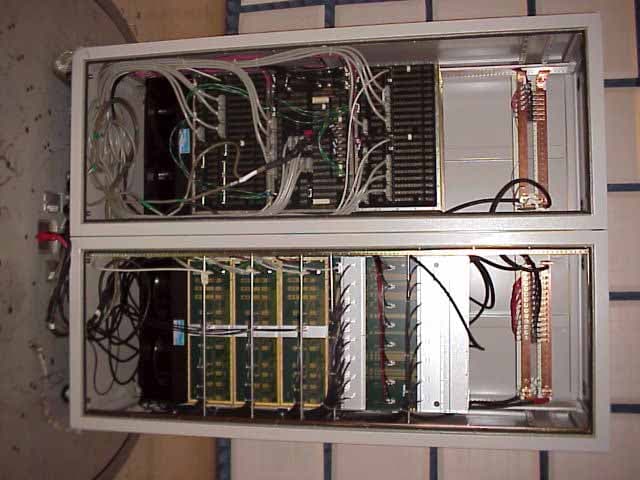
OF2FWBASE
Jun 28, 2001PCB - PCS Licensed Transmitter
Equipment Class
PCB - PCS Licensed Transmitter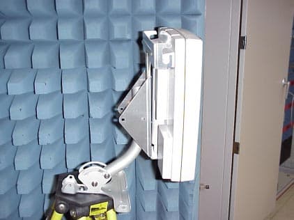
OF2WCSR30
Jun 28, 2001fixed wireless base station
Equipment Class
TNB - Licensed Non-Broadcast Station Transmitter
OF2CLRUDD3AXX
Jun 03, 2001PCS Wireless Access Network
Equipment Class
PCB - PCS Licensed Transmitter
OF2PCSR30
Jun 03, 2001Fixed Wireless Base Station
Equipment Class
PCB - PCS Licensed Transmitter