OF2WCSR30fixed wireless base station
AT&T Wireless Services, Inc.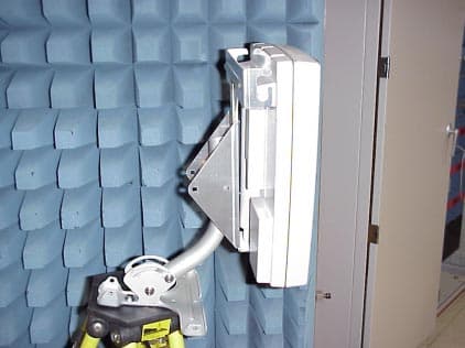
Click to zoom
Application Details
- Equipment Class
- TNB - Licensed Non-Broadcast Station Transmitter
- Date of Grant
- Jun 28, 2001
- Application Purpose
- Original Equipment
- Date of Application
- Dec 13, 2000
- Equipment Note
- fixed wireless base station
- Frequency Range
- 2350.00000000 - 2360.00000000
- Company
- AT&T Wireless Services, Inc.
- Country
- United States
Documents & Files
Document Text
Text extracted from the exhibit documents filed with the FCC. Open a document above to read the original.
Users Manual
Chapter 13:User Manuals AT&T Wireless Services13-1 11675 Rev. 1.0 12/8/00 Chapter 13User Manuals Overview TheAT&T Digital Broadband Customer Guideis included in this chapter. 1 Here Are The Basics Getting Started Domestic Calls From HomeFor calls within your own local calling area, just dial the 7- or 10 -digit phone number. For calls outside your local calling area, dial 1 first before dialing the number. Please refer to the enclosed Calling Area Map to find out which calls are within yourlocal area. Operator-Assisted CallsTo place a collect, person-to-person, or operator-assisted call from anywhere in theUnited States, dial 1 800 CALL ATT ® (1 800 225-5288) when you are away from home, or simply dial 0 from home. Service AdditionsIf you would like additional services, AT&T Digital Broadband Representatives are readyto assist you at 1 877 ATT-DGTL (1 877 288-3485) during normal business hours. Online Customer ServiceIf you have internet access, you can always refer to the AT&T Digital BroadbandCustomer Service Support site, www.care.iatt.com , for questions you may have about your service. International Calls From HomeTo place the call yourself, dial 011 + the country code + the phone number. If you don’t know the country code, or wish to have an AT&T Operator place the call for you,simply dial 0 . AT&T Digital Broadband Customer ServiceToll Free: 1 877 ATT-DGTL (1 877 288-3485) FPO AFWA20.CalifGuide w VM2d 11/22/00 11:59 AM Page 1 2 3 1 When you call from home, AT&T Digital Broadband supports only AT&T-branded calling cards. Currently, other telephone company calling cards are not supported by this service. 911 Emergency Calls For emergency police, fire, or medical assistance: 1 . Dial 911 . If 911 is not available, dial 0 . 2 . Follow the 911 operator’s instructions. You can dial 911 free of charge from any phone. Note: 911 should be used only in emergency situations in which there is immediate danger to life, health, or property.For nonemergency situations, please contact the police, fire department, or medical authorities at the number listed in your phone book, or call Directory Assistance. AT&T 00 INFO SM Directory Assistance • Simply dial 00 from home to find any listed number in the U.S., whether it’s local or long distance, even when you don’thave the exact name or location. • When you’re away from home, dial 1 800 CALL ATT (1 800 225-5288) , follow the prompts, and use your CALL ATT SM Calling Card or major credit card for billing. Calls Away From HomeYour CALL ATT Calling Card can be used for all calls, not just long distance. If you don’t have a CALL ATT Calling Card, or if you’d like to order additional cards,call 1 877 ATT-DGTL (1 877 288-3485) . There is no charge to receive the card. 1 Trying to find a friend’snew home phone numberor the number for thehotel where you’re stayingon your business trip?Here’s where you’ll findthe assistance you need.These services make it easy to stay in touch.Whether you’re callinghome to find out whatyou need to pick up atthe grocery store or calling the office from the airport, you’re alwayswithin reach. To place a call with your CALL ATT Calling Card or credit card: 1 . Dial 1 800 CALL ATT (1 800 225-5288) . 2 . Listen for the AT&T tone, then press 1 . 3 . Listen for and follow the simple, step-by-step calling instructions. Here are some timesaving tips when using your CALL ATT Calling Card or credit card:• Press # to place the next call without hanging up• Press # 123 to leave a message if the line is busy or not answered • Press ✳ to correct a mistake when dialing Inside Wire Maintenance PlanIf you have the AT&T Digital Broadband Inside Wire Maintenance Plan, call 1 877 ATT-DGTL (1 877 288-3485) or if your have internet access, visit our Web site at www.care.iatt.com to report a problem with your inside wiring and we’ll send a technician to fix the problem at no additional charge.If you choose not to subscribe to the plan and there’s a problem with your inside wiring,you’re responsible for arranging and paying for repairs.To repair the inside wiring, you can: • Call 1 877 ATT-DGTL (1 877 288-3485) to arrange for AT&T Digital Broadband to perform the repairs; you will be billed for the time necessary to complete the repairs • Hire a contractor to do the work• Perform the repairs yourself If you’re not sure whether or not your AT&T Digital Broadband plan includes the Inside Wire Maintenance Plan, 1 or if you want to sign up for it, just call 1 877 ATT-DGTL (1 877 288-3485) . FPO FPO Here Are the Basics Getting Started (cont.) 1 The AT&T Digital Broadband Inside Wire Maintenance Plan covers only telephone wiring that is in working condition at the time you sign up for service. AFWA20.CalifGuide w VM2d 11/22/00 11:59 AM Page 2 5 4 To learn more about AT&T Digital Broadband High-SpeedInternet Access, call an AT&T Digital Broadband Representative at 1 877 ATT-DGTL (1 877 288-3485) . About Your AT&T BillYour AT&T bill will include the following information:• A toll-free number for service and billing inquiries, 1 877 ATT-DGTL (1 877 288-3485). • The date the bill was calculated (bill-rendered date).• The payment due date.• Internet charges. 1 • An itemized list of long distance charges for the service period covered by the bill, including monthly service charges,listed by date incurred. • Monthly charges are billed in advance for the first full month and will be prorated from the date your service was activated,so your first bill may be up to twice as high as the expectedamount.Your next and future bills will only include one fullmonth of charges. Your AT&T DigitalBroadband packageincludes many features.If you would like to add features to your AT&T Digital Broadband at any time, just callCustomer Service at 1 877 ATT-DGTL (1 877 288-3485). Internet Access High-Speed AT&T Digital Broadband High-Speed Internet Access is available for your home. If youchoose this feature you’ll get:• Instant access to the Internet, with no need to dial up and n…
Text truncated - open the document above for the full version.
Attestation Statements
Chapter 1:Attestation Statements AT&T Wireless Services1-1 11675 Rev. 1.0 12/8/00 Chapter 1Attestation Statements FCC R3 WCS Type Acceptance Report 1-2AT&T Wireless Services 11675 Rev. 1.0 12/8/00
Cover Letter(s)
Chapter 3:Cover Letters AT&T Wireless Services3-1 11675 Rev. 1.0 12/8/00 Chapter 3Cover Letters Overview There are no cover letters for this submittal. FCC R3 WCS Type Acceptance Report 3-2AT&T Wireless Services 11675 Rev. 1.0 12/8/00
Cover Letter(s)
AT&T Wireless Group Fixed Wireless Services PO Box 97059 Redmond, WA 98073-9759 FCC R3 WCS Type Acceptance Report 11675 Revision 1.0 12/8/00 FCC R3 WCS Type Acceptance Report -2AT&T Wireless Services Solely for authorized persons having a need to know pursuant to Company Instructions11675 Rev. 1.0 12/8/00 © 1995-2000 AT&T Fixed Wireless Services All rights reserved. For additional copies of this document, please contact: AT&T Fixed Wireless Services PO Box 97059 Redmond, WA 98073-9759 Telephone: 425-702-2767 Facsimile: 425-702-3941 Ask for FCC R3 WCS Type Acceptance Report or 11675. Contents AT&T Wireless Servicesiii 11675 Rev. 1.0 12/8/00 Contents Contents. . . . . . . . . . . . . . . . . . . . . . . . . . . . . . . . . . . . . . . . . . . . . . . . . iii List of Figures . . . . . . . . . . . . . . . . . . . . . . . . . . . . . . . . . . . . . . . . . . . ix List of Tables. . . . . . . . . . . . . . . . . . . . . . . . . . . . . . . . . . . . . . . . . . . . xvii Chapter 1 Attestation Statements Chapter 2 Block Diagrams 2.1Block Diagrams. . . . . . . . . . . . . . . . . . . . . . . . . . . . . . . . . . . . . . . . . . . . 2-2 Chapter 3 Cover Letters Chapter 4 External Photographs 4.1Photographs of the R3 Indoor Unit . . . . . . . . . . . . . . . . . . . . . . . . . . . . 4-2 4.2Photographs of the R3 WCS Outdoor Unit. . . . . . . . . . . . . . . . . . . . . . 4-7 Chapter 5 ID Label/Location Information 5.1ID Label . . . . . . . . . . . . . . . . . . . . . . . . . . . . . . . . . . . . . . . . . . . . . . . . . . 5-2 5.2Location Information. . . . . . . . . . . . . . . . . . . . . . . . . . . . . . . . . . . . . . . . 5-3 Chapter 6 Internal Photographs 6.1Internal Photographs of the R3 WCS Outdoor Unit. . . . . . . . . . . . . . . 6-2 FCC R3 WCS Type Acceptance Report ivAT&T Wireless Services 11675 Rev. 1.0 12/8/00 6.2Internal Photographs of the R3 Indoor Unit . . . . . . . . . . . . . . . . . . . . . 6-9 Chapter 7 Operational Description 7.1System Overview. . . . . . . . . . . . . . . . . . . . . . . . . . . . . . . . . . . . . . . . . . . 7-2 7.1.1PWAN General Description . . . . . . . . . . . . . . . . . . . . . . . . . . . . . 7-2 7.1.2PWAN Network Element Overview . . . . . . . . . . . . . . . . . . . . . . . . 7-2 7.1.3Wireless Network Element Deployment . . . . . . . . . . . . . . . . . . . . 7-4 7.1.4PWAN Airlink Profile . . . . . . . . . . . . . . . . . . . . . . . . . . . . . . . . . . . 7-5 7.1.5PWAN Telephony Functions . . . . . . . . . . . . . . . . . . . . . . . . . . . . . 7-6 7.1.6PWAN FAX/Modem VF Traffic Functions . . . . . . . . . . . . . . . . . . . 7-9 7.1.7PWAN High-Speed Data Functions . . . . . . . . . . . . . . . . . . . . . . . 7-9 7.1.8HSD Medium Access . . . . . . . . . . . . . . . . . . . . . . . . . . . . . . . . . 7-10 7.2Airlink Overview. . . . . . . . . . . . . . . . . . . . . . . . . . . . . . . . . . . . . . . . . . . 7-11 7.2.1PWAN Physical Layer Overview . . . . . . . . . . . . . . . . . . . . . . . . . 7-11 7.2.1.1Services Provided by the Physical Layer . . . . . . . . . . 7-13 7.2.2PWAN Airlink Overview . . . . . . . . . . . . . . . . . . . . . . . . . . . . . . . 7-13 7.2.2.1PWAN Implementation of OFDM . . . . . . . . . . . . . . . . 7-15 7.2.3PWAN Airlink Resource Allocation . . . . . . . . . . . . . . . . . . . . . . . 7-18 7.2.4PWAN Network Access Channel (NAC) Functional Description 7-19 7.2.4.1BC Definition . . . . . . . . . . . . . . . . . . . . . . . . . . . . . . . . 7-19 7.2.4.2CLC Definition . . . . . . . . . . . . . . . . . . . . . . . . . . . . . . 7-19 7.2.4.3UCAC Definition . . . . . . . . . . . . . . . . . . . . . . . . . . . . . 7-20 7.2.4.4SCAC Definition . . . . . . . . . . . . . . . . . . . . . . . . . . . . . 7-20 7.2.5PWAN Voice Traffic Channel (VTch) Functional Description . . . 7-21 7.2.5.1Associated Control Channel Functional Description . 7-21 7.2.6PWAN High-Speed Data Services . . . . . . . . . . . . . . . . . . . . . . . 7-21 7.2.6.1Basic Data Service Allocation Definition . . . . . . . . . . . 7-21 7.2.6.2PWAN Data Traffic Channel (DTch) Definition . . . . . . 7-22 7.2.6.3High-Speed Data Medium Access Control . . . . . . . . . 7-23 7.2.7Network Synchronization . . . . . . . . . . . . . . . . . . . . . . . . . . . . . . 7-23 Chapter 8 Parts List/Tune Up Information 8.1Parts List . . . . . . . . . . . . . . . . . . . . . . . . . . . . . . . . . . . . . . . . . . . . . . . . 8-26 8.1.1R3 WCS Outdoor Unit PCB . . . . . . . . . . . . . . . . . . . . . . . . . . . . 8-26 8.1.2R3 Indoor Unit PCB . . . . . . . . . . . . . . . . . . . . . . . . . . . . . . . . . . 8-29 8.1.3R3 Indoor Unit 2-line Expansion PCB . . . . . . . . . . . . . . . . . . . . . 8-32 8.1.4R3 Indoor Unit Lucent AC-DC Power Supply . . . . . . . . . . . . . . . 8-33 8.1.5R3 Indoor Unit Panasonic AC-DC Power Supply . . . . . . . . . . . . 8-34 Contents AT&T Wireless Servicesv 11675 Rev. 1.0 12/8/00 8.1.6R3 WCS Outdoor Unit Lucent DC-DC Power Module . . . . . . . . 8-36 8.2Output Power Tuning Procedures. . . . . . . . . . . . . . . . . . . . . . . . . . . . 8-37 8.2.1Hardware Output Power Limiting Circuit . . . . . . . . . . . . . . . . . . 8-37 8.2.2Software Output Power Control . . . . . . . . . . . . . . . . . . . . . . . . . 8-39 8.2.3Manufacturing Calibration . . . . . . . . . . . . . . . . . . . . . . . . . . . . . 8-40 8.2.4Hardware Frequency vs Temperature Results . . . . . . . . . . . . . . 8-40 Chapter 9 RF Exposure 9.1RF Human Exposure - FDTD Analysis and SAR Testing . . . . . . . . . . 9-2 9.1.1Applicable FCC Rules . . . . . . . . . . . . . . . . . . . . . . . . . . . . . . . . . 9-2 9.1.2Test Configuration . . . . . . . . . . . . . . . . . . . . . . . . . . . . . . . . . . . . 9-2 9.1.2.1Modelling . . . . . . . . . . . . . . . . . . . . . . . . . . . . . . . . . . . 9-2 9.1.2.2SAR Testing . . . . . . . . . . . . . . . . . . . . . . . . . . . . . . . . 9-2 9.1.3Test Results . . . . . . . . . . . . . . . . . . . . . . . . . . . . . . . . . . . . . . . …
Text truncated - open the document above for the full version.
Cover Letter(s)
Confirmation Number EA99518 FCC ID: OF2WCSR30 Please associate the following contact information with the above-referenced application. Technical Contact: AT&T Wireless Services, Inc. Keith Peavler Telephone: 425-702-2914 Fax: 425-702-2521 Email: [email protected] Non-technical Contact: AT&T Wireless Services, Inc. Lisa Volpe Telephone: 202-416-6519 Fax: 202-223-9095 Email: [email protected] 1150 Connecticut Avenue, NW, 4 th Floor Washington, DC 20036
External Photos
Chapter 4:External Photographs AT&T Wireless Services4-1 11675 Rev. 1.0 12/8/00 Chapter 4External Photographs Overview This section contains external photographs of the R3 Indoor Unit and the R3 WCS Outdoor Unit. Contents 4.1Photographs of the R3 Indoor Unit . . . . . . . . . . . . . . . . . . . . . . . . . . 4-2 4.2Photographs of the R3 WCS Outdoor Unit. . . . . . . . . . . . . . . . . . . . 4-7 FCC R3 WCS Type Acceptance Report 4-2AT&T Wireless Services 11675 Rev. 1.0 12/8/00 4.1Photographs of the R3 Indoor Unit The front face of the R3 Indoor Unit has an HB plastic decorative cover with a power LED inset as shown inFigure 4.1. The enclosure is a sheet metal formed rectangular box measuring approximately 16 3/4”x12 1/2”x3 1/2”. Figure 4.1Front of the R3 Indoor Unit Chapter 4:External Photographs AT&T Wireless Services4-3 11675 Rev. 1.0 12/8/00 Figure 4.2 shows the R3 Indoor Unit, which identifies both front and side ventilation. Figure 4.2Right-side view of the R3 Indoor Unit FCC R3 WCS Type Acceptance Report 4-4AT&T Wireless Services 11675 Rev. 1.0 12/8/00 Figure 4.3 is a close-up view of the R3 Indoor Unit left side, which details the unit’s ventilation characteristics. Figure 4.3Side View of the R3 Indoor Unit Chapter 4:External Photographs AT&T Wireless Services4-5 11675 Rev. 1.0 12/8/00 Figure 4.4 shows the back-side of the R3 Indoor Unit. From left to right, the connections are as follows: • Power cable, standard 120 VAC input • Telco cabling, voice lines 1 and 2 • Telco cabling, voice lines 3 and 4 (expansion card used only when ordered by the customer) • RG-6 coaxial RF interconnection to R3 WCS Outdoor Unit Figure 4.4 identifies the worst-case cabling configuration. Note:Figure 4.4 also shows the UL/FCC label location. Figure 4.4Rear view of the R3 Indoor Unit FCC R3 WCS Type Acceptance Report 4-6AT&T Wireless Services 11675 Rev. 1.0 12/8/00 Figure 4.5 depicts the gas tube surge protector manufactured by NEXTEC. This protects the R3 Indoor Unit from indirect surges and transients that may flow on the coax to the R3 Indoor Unit. The coax provides DC voltage to the R3 WCS Outdoor Unit, along with Ethernet connection. Figure 4.5R3 WCS Surge Protector Chapter 4:External Photographs AT&T Wireless Services4-7 11675 Rev. 1.0 12/8/00 4.2Photographs of the R3 WCS Outdoor Unit The front face of the R3 WCS Outdoor Unit has an HB plastic radome which connects to a metallic back frame. The radome shown in Figure 4.6, covers the antenna and measures approximately 12 inches by 14 inches. Figure 4.6Front View of the R3 WCS Outdoor Unit Antenna FCC R3 WCS Type Acceptance Report 4-8AT&T Wireless Services 11675 Rev. 1.0 12/8/00 Figure 4.7shows the R3 WCS Outdoor Unit back view which identifies the RG-6 coaxial cable connections. The RG-6 coaxial connections provide the Ethernet connection and DC power to the R3 WCS Outdoor Unit from the R3 Indoor Unit. Figure 4.7Rear View of the R3 WCS Outdoor Unit Chapter 4:External Photographs AT&T Wireless Services4-9 11675 Rev. 1.0 12/8/00 Figure 4.8shows the R3 WCS Outdoor Unit side view with the typical metallic mounting bracket. Figure 4.8Side View of the Outdoor Unit with Mounting Bracket FCC R3 WCS Type Acceptance Report 4-10AT&T Wireless Services 11675 Rev. 1.0 12/8/00
ID Label/Location Info
Chapter 5:ID Label/Location Information AT&T Wireless Services5-1 11675 Rev. 1.0 12/8/00 Chapter 5ID Label/Location Information Overview This section contains ID label and location information. Contents 5.1ID Label . . . . . . . . . . . . . . . . . . . . . . . . . . . . . . . . . . . . . . . . . . . . . . 5-2 5.2Location Information . . . . . . . . . . . . . . . . . . . . . . . . . . . . . . . . . . . . 5-3 FCC R3 WCS Type Acceptance Report 5-2AT&T Wireless Services 11675 Rev. 1.0 12/8/00 5.1ID Label Figure 5.1shows the FCC ID label that is located on both the R3 WCS Outdoor Unit and the R3 Indoor Unit. The R3 Indoor Unit will be FCC certified, while the R3 WCS Outdoor Unit will obtain an FCC Type Approval. Figure 5.1FCC ID Label for the R3 Indoor Unit Figure 5.2FCC ID Label for the R3 WCS Outdoor Unit Chapter 5:ID Label/Location Information AT&T Wireless Services5-3 11675 Rev. 1.0 12/8/00 5.2Location Information Figure 5.3 shows the FCC ID label location on the backside of the R3 WCS Outdoor Unit. Figure 5.3FCC ID Label Location on Antenna FCC R3 WCS Type Acceptance Report 5-4AT&T Wireless Services 11675 Rev. 1.0 12/8/00 Figure 5.4 shows a close-up of the FCC ID label on the R3 WCS Outdoor Unit. Note the FCC ID number. Figure 5.4Close-up of Label on R3 WCS Outdoor Unit Chapter 5:ID Label/Location Information AT&T Wireless Services5-5 11675 Rev. 1.0 12/8/00 Figure 5.5 shows the FCC ID label location on the R3 Indoor Unit. Figure 5.5FCC ID Label Location on the R3 Indoor Unit FCC R3 WCS Type Acceptance Report 5-6AT&T Wireless Services 11675 Rev. 1.0 12/8/00 Figure 5.6shows a close-up of the FCC ID label on the R3 Indoor Unit. Figure 5.6FCC Label Location on R3 Indoor Unit
RF Exposure Info
Chapter 9:RF Exposure AT&T Wireless Services9-1 11675 Rev. 1.0 12/8/00 Chapter 9RF Exposure Overview This chapter contains information as to how the product was determined to be compliant with FCC Part 24 subsection 24.51 Contents 9.1RF Human Exposure - FDTD Analysis and SAR Testing . . . . . . . . 9-2 9.2Summary and Conclusions . . . . . . . . . . . . . . . . . . . . . . . . . . . . . . . . 9-4 9.3Computer Hardware and Software Used for Performing Calculations . 9-4 9.42 FDTD Models . . . . . . . . . . . . . . . . . . . . . . . . . . . . . . . . . . . . . . . . 9-5 9.5FDTD Calculation and Measurements of SAR in Kuster Head and Shoulders Homogeneous Model . . . . . . . . . . . . . . . . . . . . . . . . . . . 9-14 9.6FDTD Calculation of SAR in REMCOM Head and Shoulders Inhomogeneous Model (no radome attached). . . . . . . . . . . . . . . . . 9-23 FCC R3 WCS Type Acceptance Report 9-2AT&T Wireless Services 11675 Rev. 1.0 12/8/00 9.1RF Human Exposure - FDTD Analysis and SAR Testing 9.1.1Applicable FCC Rules FCC Subpart 24.51 - Applications for Type Approval of transmitters operating within the PCS region must determine that the equipment complies with IEEE C95.1-1991, “IEEE Standards for Safety Levels with Respect to Human Exposure to Radio Frequency Electromagnetic Fields, 3 kHz to 300 GHz” as measured using methods specified in IEEE C95.3 - 1991, “Recommended Practice for the Measurement of Potentially Hazardous Electromagnetic Fields - RF and Microwave.” 9.1.2Test Configuration RF human exposure configurations were setup, tested, and evaluated by the following independent laboratories for the original Remote Unit. The R3 WCS is a revision of the original PCS version and utilizes the same enclosures with a WCS revised antenna. Modifications were made to the antenna for utilization within the WCS spectrum, therefore, additional modelling was completed by Dr. William Guy. Due to the accuracy of correlation from the modelling to the SAR testing, AT&T feels that modelling of this product revision is adequate. 9.1.2.1 Modelling Modelling was performed on both Remote Units R1, R3 PCS, and R3 WCS by Bioelectromagnetics Consulting, 18122 60th Pl. N.E., Kenmore, Washington 98028, with Dr. William Guy as primary consultant, responsible for carrying out the FDTD numerical analysis of the near fields, far fields, and SAR distributions from the R3 WCS Outdoor Unit. As primary consultant, additional responsibilities included the evaluation and analysis of the SAR data from the independent SAR measurement laboratories utilized during SAR measurements of the R1. 9.1.2.2 SAR Testing SAR testing performed on the original R1 Remote Unit and correlated to the models by SAR testing Schmid & Partner Engineering AG (SPEAG), Staffelstrasse 8, 8045 Zurich, Switzerland, with Dr. Neils Kuster as the project director, who was responsible for carrying out measurements of the near and far fields for the R1 Outdoor Unit and Chapter 9:RF Exposure AT&T Wireless Services9-3 11675 Rev. 1.0 12/8/00 SAR distribution in homogeneous phantom head and a flat rectangular tissue models exposed to the antenna fields. SARTest Ltd., Oakfield Laboratories, Cudworth Lane, Newdigate, Surrey RH5 5DR. UK., with M.I. Manning as project director, who was responsible for carrying out measurements of the near and far fields for the R1 Outdoor Unit and SAR distribution in a heterogeneous phantom head model and a flat heterogeneous rectangular tissue model exposed to the antenna fields. 9.1.3Test Results Bioelectromagnetics Consulting completed the FDTD measurements on the R3 WCS Cushcraft antenna, and found the product to be compliant with FCC Subpart 27.52 as it relates to WCS spectrum. The results of the SAR calculations are summarized inTable 9.1. Table 9.1Summary and Comparison of Calculated and Measured Maximum SARs to FCC MPL for Various Tissue Models Exposed to AT&T R3 WCS Cushcraft Antenna. Model Peak SAR (W/kg) e.i.r.p. = 4.0 W 1 Gram Avg. SAR (W/kg) e.i.r.p. = 4.0 W dB from FCC MPL e.i.r.p. = 2.0 We.i.r.p. = 3.0 We.i.r.p. = 4.0 W SPEAG Head, nose over array 1.110.570-7.48-5.73-4.48 SPEAG Head, nose over patch 1 1.730.878-5.61-3.86-2.61 SPEAG Head, nose over patch 1 with radome 1.120.721-6.46-4.71-3.46 SPEAG Head, nose over patch 2 0.8830.507-6.17-4.42-3.17 SPEAG Head, nose over patch 4 1.050.631-7.04-5.29-4.04 REMCOM Head, nose over patch 1 2.390.715-7.47-5.72-4.47 FCC R3 WCS Type Acceptance Report 9-4AT&T Wireless Services 11675 Rev. 1.0 12/8/00 9.2Summary and Conclusions The FDTD method was used to calculate the far field antenna patterns and near electric and magnetic fields for the AT&T Cushcraft 2.357 GHz antenna radiating in free space for an input power of 158.5 mW split evenly between two coaxial antenna input feeds. The antenna patterns and gain closely agreed with the antenna manufacturer’s measured values. The SPEAG (Schmid & Partner, Engineering AG (SPEAG), Staffelstrasse 8, 8045 Zurich, Switzerland) homogeneous head model (Kuster head model) and the REMCOM inhomogeneous head model used in the previous AT&T RU Antenna study as reported in January 12, 1999 were also used in this study. The finite difference time domain (FDTD) technique was used to calculate the near and far fields and induced SAR patterns in exposed tissues from the antenna. The FDTD technique is currently the most popular theoretical method of choice for analyzing the safety and compliance of wireless technology devices with human RF exposure MPLs. 9.3Computer Hardware and Software Used for Performing Calculations 9.3.1Computer Hardware The theoretical calculations were performed on a dual Pentium 500 MHz, home built PC Workstation equipped with a SuperMicro P6DGU motherboard containing 2.0 Gbyte of RAM and 80 Gbytes of hard disk space operating under Windows 2000 Server Operating System. 9.3.2Computer Software An FDTD software package commercially available from REMCOM Corporation [State College, PA], called XFDTD (version 505) was used to carry out all …
Text truncated - open the document above for the full version.
Test Report
Chapter 11:Test Report AT&T Wireless Services11-1 11675 Rev. 1.0 12/8/00 Chapter 11Test Report Overview This section includes the test report and data showing compliance with all applicable FCC, Chapter 47 technical standards. Contents 11.1Test Methodology . . . . . . . . . . . . . . . . . . . . . . . . . . . . . . . . . . . . . . 11-2 11.2RF Characterization Test Results . . . . . . . . . . . . . . . . . . . . . . . . . 11-32 11.3Electromagnetic Compatibility Test Results. . . . . . . . . . . . . . . . . 11-62 11.4R3 WCS Outdoor Unit Specifications . . . . . . . . . . . . . . . . . . . . 11-130 FCC R3 WCS Type Acceptance Report 11-2AT&T Wireless Services 11675 Rev. 1.0 12/8/00 11.1 Test Methodology This section describes the test methodology used to validate the performance of the AT&T Wireless Services R3 WCS system, which consists of the R3 Indoor Unit and the R3 WCS Outdoor Unit, against the applicable requirements of FCC Part 2, 15, and Part 27. 11.1.1 Introduction The purpose of this chapter is to present the test methodology used to verify FCC regulatory compliance of the R3 WCS system. Throughout this document, all depictions of test configurations utilize a common set of interfaces. These interfaces are described in detail in Chapter 7, “Operational Description” of this document. The name and purpose of each interface is summarized inTable 11.1 below: Table 11.1 PWAN Interface Definitions 11.1.2 Equipment Classification The AT&T R3 WCS Outdoor Unit is designed to be mounted to a building, therefore it is classified as a “fixed station” as defined in Subpart 27.5 of the FCC Rules and Regulations. Consequently, the output power limitations associated with Base Stations described under FCC Subpart 27.50 were applied to this unit. However, it should be noted that the Effective Isotropic Radiated Power (EIRP) of the R3 WCS system will not exceed 4 watts EIRP average power. Interface IDDescription T InterfaceTerminal interface to R3 A InterfaceAir interface between R3 and Base Station radio equipment P InterfaceInterface between Base Station radio equipment and Base Station control Csw InterfaceInterface that provides public switched telephone network (PSTN) connectivity for call processing Chapter 11:Test Report AT&T Wireless Services11-3 11675 Rev. 1.0 12/8/00 11.1.3 Remote Unit RF Frequency Stability vs. Temperature Test Methodology 11.1.3.1 Applicable FCC Rules Parts FCC Subpart 2.995 - Measured over the temperature range of -30 to +50 C. Frequency measurements shall be made at the extremes and at intervals of not greater than 10 degrees C throughout the range. Only the frequency determining portions of the transmitter need be subjected to this test. FCC Subpart 27.54 - The frequency stability shall be sufficient to ensure that the fundamental emission stays within the authorized bands of operation. 11.1.3.2 Overview The R3 WCS obtains its frequency stability from the serving Base Station by synchronizing its internal TCXO to the serving Base Station frequency reference pilots. If a R3 WCS is unable to locate the reference pilots from the serving Base Station, it will not transmit. Consequently, the frequency accuracy of the R3 WCS can be verified only while it is receiving a transmission from a Base Station. Once an R3 WCS has synchronized to the serving Base, it is capable of transmitting Delay Compensation Pilots (DCPs) upon request. DCPs consist of 17 tones with static modulation (fixed amplitude and phase) spaced at 59.375-kHz intervals beginning 23.4375 kHz from the lower edge of the 1-MHz transmit subband (refer toFigure 11.1). Any frequency error present in the R3 WCS Outdoor Unit’s reference oscillator and synchronization circuits will create a corresponding frequency error in each transmitted DCP tone. FCC R3 WCS Type Acceptance Report 11-4AT&T Wireless Services 11675 Rev. 1.0 12/8/00 Figure 11.1 R3 WCS Delay Compensation Pilot Frequency Relationships 11.1.3.3 Test Methodology The R3 WCS Outdoor Unit under test was placed into a Screening Systems, Inc. model QRS-410T thermal chamber. The standard R3 WCS Outdoor Unit antenna was replaced with a special pin-thru connector built for direct connection to the antenna port, capable of supporting a direct RF connection. This change allowed a direct cabled connection between the Base Station and the R3 WCS Outdoor Unit while maintaining the integrity and thermal characteristics of the housing (refer toFigure 11.2). DCPDCPDCPDCPDCPDCPDCP DCP DCP DCPDCPDCPDCPDCPDCPDCP DCP 23.4375 kHz 5 MHz WCS Block 1 MHz 1 MHz 1 MHz 1 MHz 500 kHz Guardband 500 kHz Guardband Subband A Subband B Subband C Subband D 59.375 kHz 26.5625 kHz 12345678 9 10 111213141516 17 Chapter 11:Test Report AT&T Wireless Services11-5 11675 Rev. 1.0 12/8/00 Figure 11.2 R3 WCS Frequency Stability vs. Temperature Test Configuration A Base Station, in an adjacent room, supplied the downlink signal necessary to permit synchronization of the R3 WCS. The Base Station reference oscillator was phase locked to the GPS for the duration of the R3 WCS frequency stability tests. The frequency counter in a Hewlett- Packard 8563A Spectrum Analyzer was used to monitor the frequency of DCP tone #7 from the R3 WCS under test. A Hewlett-Packard 5071A cesium beam primary standard was utilized as a precision frequency reference for the spectrum analyzer’s frequency counter. The spectrum analyzer’s frequency counter resolution was set to 1 Hz. Lucent 5ESS Switch AT&T Wireless Services TR-303 Network Interface and Baseband Shelf H/P5071A Cesium Beam Primary Reference Standard H/P 8563ESpectrum Analyzer WCS RF Base Station Equipment P Interface 10 MHz Reference Csw Interface External 10 MHz Reference Input AT&T Wireless Services R3 WCS Outdoor Unit (DUT) Antenna Port LPA #1 0-110 dB, 50 Ohm Attenuator 10 MHz Output #1 RF Input Screening Systems, Inc. QRS-410T Thermal Chamber -20 dB Directional Coupler Narda 3022 Antenna Port A Interface GPS Antenna Laptop computer running H/P BenchLink data…
Text truncated - open the document above for the full version.
Test Report
FCC ID: OF2WCSR30 731 Confirmation Number: EA99518 Correspondence Number 17944 1) Confidentiality letter: AT&T Wireless Services, Inc. respectfu…
Text truncated - open the document above for the full version.
Contact Information
Applicant
Douglas I Brandon(Vice President)
Technical Specifications
| # | Rule Parts | Frequency Range | Power Output | Emission | Tolerance |
|---|---|---|---|---|---|
| 1 | 27 | 2.35 GHz - 2.36 GHz | 4 W | 1M00W7W | 0.1000000000 ppm |
Other Applications from AT&T Wireless Services, Inc.
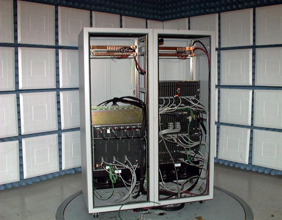
OF2FWBASE15PCS
Dec 06, 2001fixed wireless base station
Equipment Class
PCB - PCS Licensed Transmitter
OF2FWBASE15WCS
Jul 22, 2001fixed wireless base station
Equipment Class
TNB - Licensed Non-Broadcast Station Transmitter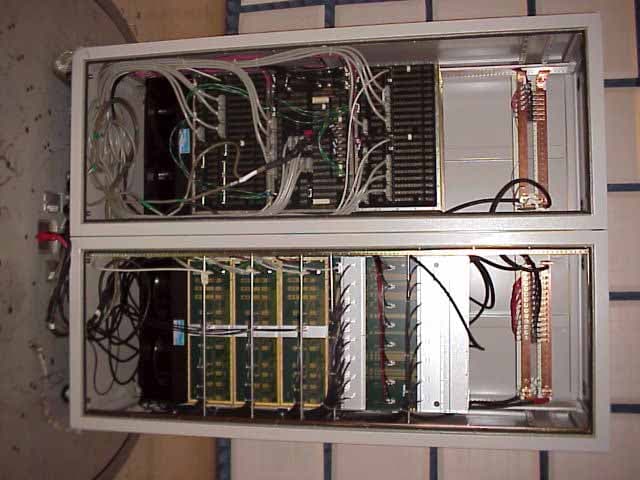
OF2FWBASE
Jun 28, 2001PCB - PCS Licensed Transmitter
Equipment Class
PCB - PCS Licensed Transmitter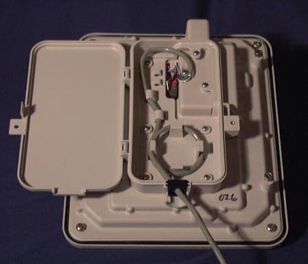
OF2CLRUDD3AXX
Jun 03, 2001PCS Wireless Access Network
Equipment Class
PCB - PCS Licensed Transmitter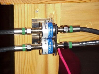
OF2PCSR30
Jun 03, 2001Fixed Wireless Base Station
Equipment Class
PCB - PCS Licensed Transmitter