OF2FWBASE15WCSfixed wireless base station
AT&T Wireless Services, Inc.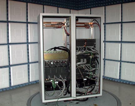
Click to zoom
Application Details
- Equipment Class
- TNB - Licensed Non-Broadcast Station Transmitter
- Date of Grant
- Jul 22, 2001
- Application Purpose
- Original Equipment
- Date of Application
- May 30, 2001
- Equipment Note
- fixed wireless base station
- Frequency Range
- 2305.00000000 - 2315.00000000
- Company
- AT&T Wireless Services, Inc.
- Country
- United States
Documents & Files
Document Text
Text extracted from the exhibit documents filed with the FCC. Open a document above to read the original.
Users Manual
Chapter 13:Users Manuals AT&T Wireless GroupAT&T Proprietary (Restricted)13-1 11830 Rev. 1.0 5/22/01Solely for authorized persons having a need to know pursuant to Company Instructions Chapter 13Users Manuals A users manual has not been included within this Type Acceptance Application. The FWAN WCS Base Station is delivered, installed, and maintained by AT&T and/or authorized personnel. Base Station (B1.5 WCS) FCC Type Acceptance Application 13-2AT&T Proprietary (Restricted)AT&T Wireless Group Solely for authorized persons having a need 11830Rev.1.0 5/22/01 to know pursuant to Company Instructions
Attestation Statements
Chapter 1:Attestation Statements AT&T Wireless GroupAT&T Proprietary (Restricted)1-1 11830 Rev. 1.0 5/22/01Solely for authorized persons having a need to know pursuant to Company Instructions Chapter 1Attestation Statements Base Station (B1.5 WCS) FCC Type Acceptance Application 1-2AT&T Proprietary (Restricted)AT&T Wireless Group Solely for authorized persons having a need 11830Rev.1.0 5/22/01 to know pursuant to Company Instructions
Cover Letter(s)
Chapter 3:Cover Letters AT&T Wireless GroupAT&T Proprietary (Restricted)3-1 11830 Rev. 1.0 5/22/01Solely for authorized persons having a need to know pursuant to Company Instructions Chapter 3Cover Letters Overview This section describes functional product interaction with other products pending FCC approval. Contents 3.1FWAN WCS Base Station—System-Dependent Products . . . . . . . . 3-2 Base Station (B1.5 WCS) FCC Type Acceptance Application 3-2AT&T Proprietary (Restricted)AT&T Wireless Group Solely for authorized persons having a need 11830Rev.1.0 5/22/01 to know pursuant to Company Instructions 3.1 FWAN WCS Base Station—System-Dependent Products This unit, the FWAN WCS Base Station, comprises the second half of the FWAN WCS System. Currently, the R3 WCS has undergone FCC evaluation for certified FCC Type Approval and, per the Grant of Equipment Authorization, was assigned the following FCC Identifier: OF2WCSR30. The Remote Unit is located at remote residences and in concert with the FWAN WCS Base Station completes the FWAN WCS System. This application for FWAN WCS Base Station Type Approval is for a Class A commercial product that will function in concert with the aforementioned Remote Unit to complete the FWAN WCS System, providing wireless loop service. This system operates in the WCS Spectrum Blocks A and B and can communicate with the following products: • Remote Unit 3 WCS, FCC I.D. OF2WCSR30
Cover Letter(s)
AT&T Wireless Services, Inc. 1150 Connecticut Avenue, N.W. 4 th Floor Washington DC 20036 (202) 223-9222 Fax (202) 223-9095 July 19, 2001 Richard Fabina, Chief Equipment and Authorization Branch Office of Engineering and Technology Federal Communications Commission Washington DC 20554 In re: AT&T Wireless Services, Inc. Equipment Authorization OF2FWBase15WCS Confirmation Number EA101181 Request for Confidential Treatment of Exhibits Dear Mr. Fabina: Pursuant to the provisions of Sections 0.459(a) and (b), AT&T Wireless Services, Inc. (“AWS”) respectfully requests confidential treatment pursuant to Section 0.457(d) of the following Exhibits in the above-referenced Equipment Authorization Grant: Exhibit DescriptionExhibit Section Block DiagramChapter 2 Internal PhotosChapter 6 Operational DescriptionChapter 7 Parts List Tune Up InformationChapter 8 Schematic Dia gramsChapter 10 Each of the foregoing exhibits constitute trade secrets and commerical information relating to the Equipment Authorization that AWS would not normally make publicly available. Disclosure of such information could provide competitors of AWS with information that would put AWS at a competitive disadvantage in the market place. Mr. Richard Fabina May 31, 2001 Page Two For the foregoing reasons, AT&T Wireless Services, Inc. requests confidential treatment for the exhibits for the above-referenced application. Respectfully submitted, AT&T Wireless Services, Inc. ___________________________________ David C. Jatlow Vice President, Federal Regulatory Affairs
External Photos
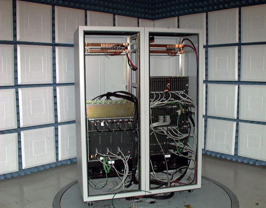
Chapter 4:External Photographs AT&T Wireless GroupAT&T Proprietary (Restricted)4-1 11830 Rev. 1.0 5/22/01Solely for authorized persons having a need to know pursuant to Company Instructions Chapter 4External Photographs Overview This section contains external photographs of the FWAN WCS Base Station. Contents 4.1External Photographs . . . . . . . . . . . . . . . . . . . . . . . . . . . . . . . . . . . . 4-2 Base Station (B1.5 WCS) FCC Type Acceptance Application 4-2AT&T Proprietary (Restricted)AT&T Wireless Group Solely for authorized persons having a need 11830Rev.1.0 5/22/01 to know pursuant to Company Instructions 4.1 External Photographs The front view of the FWAN WCS Base Station shows internal access via double doors. The double cabinet may be separated for various installation considerations. There are independent casters for additional mobility. Figure 4.1Front Corner View of the FWAN WCS Base Station AT&T Wireless GroupAT&T Proprietary (Restricted)4-3 11830 Rev. 1.0 5/22/01Solely for authorized persons having a need to know pursuant to Company Instructions Chapter 4:External Photographs The FWAN WCS Base Station, as shown inFigure 4.2, places digital functionality in the left cabinet and the RF functionalities in the right cabinet for separation at various installations. Each cabinet is independently powered with circuit breaker protection and air-moving devices. Figure 4.2Open Doors Front View of FWAN WCS Base Station Base Station (B1.5 WCS) FCC Type Acceptance Application 4-4AT&T Proprietary (Restricted)AT&T Wireless Group Solely for authorized persons having a need 11830Rev.1.0 5/22/01 to know pursuant to Company Instructions The interconnecting cabling between the digital and RF cabinets is shown inFigure 4.3. Figure 4.3Open Panels Back View of the FWAN WCS Base Station AT&T Wireless GroupAT&T Proprietary (Restricted)4-5 11830 Rev. 1.0 5/22/01Solely for authorized persons having a need to know pursuant to Company Instructions Chapter 4:External Photographs The back of the FWAN WCS Base Station cabinet contains airflow ventilation as shown inFigure 4.4. Figure 4.4Back View of the FWAN WCS Base Station Base Station (B1.5 WCS) FCC Type Acceptance Application 4-6AT&T Proprietary (Restricted)AT&T Wireless Group Solely for authorized persons having a need 11830Rev.1.0 5/22/01 to know pursuant to Company Instructions
ID Label/Location Info
Chapter 5:ID Label/Location Information AT&T Wireless GroupAT&T Proprietary (Restricted)5-1 11830 Rev. 1.0 5/22/01Solely for authorized persons having a need to know pursuant to Company Instructions Chapter 5ID Label/Location Information Overview This section contains information about the content and placement of the FCC label for the FWAN WCS Base Station. Contents 5.1ID Label. . . . . . . . . . . . . . . . . . . . . . . . . . . . . . . . . . . . . . . . . . . . . . . 5-2 5.2Location Information. . . . . . . . . . . . . . . . . . . . . . . . . . . . . . . . . . . . . 5-3 Base Station (B1.5 WCS) FCC Type Acceptance Application 5-2AT&T Proprietary (Restricted)AT&T Wireless Group Solely for authorized persons having a need 11830Rev.1.0 5/22/01 to know pursuant to Company Instructions 5.1 ID Label Figure 5.1Sample FCC ID Label AT&T Wireless GroupAT&T Proprietary (Restricted)5-3 11830 Rev. 1.0 5/22/01Solely for authorized persons having a need to know pursuant to Company Instructions Chapter 5:ID Label/Location Information 5.2 Location Information Figure 5.2FCC Compliance Label—Possible Exterior Location, RF Cabinet Back Base Station (B1.5 WCS) FCC Type Acceptance Application 5-4AT&T Proprietary (Restricted)AT&T Wireless Group Solely for authorized persons having a need 11830Rev.1.0 5/22/01 to know pursuant to Company Instructions Figure 5.3FCC Compliance Label—Possible Exterior Location, RF Cabinet Side
RF Exposure Info
Chapter 9:RF Exposure Information AT&T Wireless GroupAT&T Proprietary (Restricted)9-1 11830 Rev. 1.0 5/22/01Solely for authorized persons having a need to know pursuant to Company Instructions Chapter 9RF Exposure Information Overview This chapter contains information on how the product was determined to be compliant with FCC Rules, Part 24, subsection 24.51. Contents 9.1RF Human Exposure . . . . . . . . . . . . . . . . . . . . . . . . . . . . . . . . . . . . . 9-2 Base Station (B1.5 WCS) FCC Type Acceptance Application 9-2AT&T Proprietary (Restricted)AT&T Wireless Group Solely for authorized persons having a need 11830Rev.1.0 5/22/01 to know pursuant to Company Instructions 9.1 RF Human Exposure 9.1.1Applicable FCC Rules FCC Subpart 24.51 - Applicants for Type Approval of transmitters operating within the WCS region must determine that the equipment complies with IEEE C95.1-1991,IEEE Standards for Safety Levels with Respect to Human Exposure to Radio Frequency Electromagnetic Fields, 3 kHz to 300 GHz as measured using methods specified in IEEE C95.3 - 1991,Recommended Practice for the Measurement of Potentially Hazardous Electromagnetic Fields - RF and Microwave. 9.1.2FWAN WCS Test Configuration Maximum Permissible Exposure (MPE) configuration will be completed per FCC MPE Site Requirements. MPE testing will be performed on each FWAN WCS Base Station installed. MPE data, analysis, and required paperwork will be stored and filed with the FCC per regulatory requirements.
Test Report
Chapter 11:Test Reports AT&T Wireless GroupAT&T Proprietary (Restricted)11-1 11830 Rev. 1.0 5/22/01Solely for authorized persons having a need to know pursuant to Company Instructions Chapter 11Test Reports Overview This section contains the test reports and data that show that the FWAN WCS Base Station B1.5 is in compliance with all applicable technical standards and FCC Rules and Regulations. Contents 11.1Test Methodology . . . . . . . . . . . . . . . . . . . . . . . . . . . . . . . . . . . . . . 11-2 11.2RF Characterization Test Results . . . . . . . . . . . . . . . . . . . . . . . . . 11-28 11.3Electromagnetic Compatibility Test Results . . . . . . . . . . . . . . . . . 11-85 Base Station (B1.5 WCS) FCC Type Acceptance Application 11-2AT&T Proprietary (Restricted)AT&T Wireless Group Solely for authorized persons having a need 11830Rev.1.0 5/22/01 to know pursuant to Company Instructions 11.1 Test Methodology This section describes the test methodology used to validate the performance of the AT&T Wireless Services FWAN WCS Base Station B1.5 against the applicable requirements of the Code of Federal Regulations, FCC Rules - Parts 2, 15, and 27 and thus verify FCC regulatory compliance of the FWAN WCS Base Station. Throughout this document, all depictions of test configurations utilize a common set of interfaces. These interfaces are described in detail inChapter 7, “Operational Description.” The name and purpose of each interface is summarized inTable 11.1 below: 11.1.1 Frequency Stability vs. Temperature 11.1.1.1 Applicable FCC Rules FCC Subpart 2.1055 - Measured over the temperature range of -30 to +50 degrees Celsius. Frequency measurements shall be made at the extremes and at intervals of not greater than 10 Celsius degrees throughout the range. Only the frequency-determining portions of the transmitter need be subjected to this test. FCC Subpart 27.54 - The frequency stability shall be sufficient to ensure that the fundamental emission stays within the authorized frequency block. 11.1.1.2 Overview The FWAN WCS Base Station obtains its frequency stability from GPS-disciplined 10 MHz ovenized oscillators located on the station’s primary and redundant synchronization cards. Either synchronization card is capable of functioning in one of the following three operational modes: Oscillator Operating in GPS Locked Mode: During normal operation, the frequency of the 10 MHz oscillator is disciplined by GPS to an accuracy of approximately 0.005 PPM deviation. Oscillator Operating in GPS Holdover Mode: In the event that GPS signals are lost (due to an antenna or GPS receiver failure), the 10 MHz oscillator will utilize the most current correction data Table 11.1FWAN WCS Interface Definitions Interface IDDescription T InterfaceTerminal interface to Remote Units A InterfaceAir interface between Remote Units and Base Station radio equipment P InterfaceInterface between Base Station radio equipment and Base Station control Csw InterfaceInterface that provides public switched telephone network (PSTN) connectivity for call processing AT&T Wireless GroupAT&T Proprietary (Restricted)11-3 11830 Rev. 1.0 5/22/01Solely for authorized persons having a need to know pursuant to Company Instructions Chapter 11:Test Reports obtained from the on-board GPS receiver to maintain an accuracy of approximately 0.02 PPM deviation over a 24-hour period. Oscillator Operating in GPS Free-Run mode:In the event that GPS is completely unobtainable, the 10 MHz oscillator will free-run with an accuracy of approximately 0.2 PPM deviation. The 10-MHz disciplined oscillators on the primary and redundant synchronization cards serve as the main frequency-determining element in the Base Station. Any frequency error present in the 10 MHz output of the synchronization cards will create a corresponding frequency error in each transmitted OFDM tone at the Base Station operating frequency. The Base Station also contains its own low stability (approx. 5 PPM deviation) 10-MHz reference oscillator. This internal oscillator is phase-locked to the active synchronization card for the purpose of minimizing the effects of reference oscillator phase noise. The Base Station software is designed to disable RF output power in the event that both of the synchronization cards fail (or are not present). As a result, the Base Station will not transmit while using the internal oscillator as its 10-MHz reference. 11.1.1.3 Test Methodology The synchronization card under test was placed into a Screening Systems, Inc. model QRS-410T thermal chamber (refer toFigure 11.1). A Hewlett-Packard 53132 frequency counter was used to monitor the output frequency of the DUT. A Hewlett-Packard 5071A cesium beam primary standard was utilized as a precision frequency reference for the 53132A frequency counter. The frequency counter resolution was set to 0.001 Hz. The frequency accuracy of the 10 MHz oscillator was tracked over the temperature range of -30 to +50 degrees Celsius. During this test the thermal chamber “stair-stepped” from -40 to +60 degrees Celsius in temperature increments of 10 Celsius degrees. The thermal chamber’s sensing thermocouple was attached to the synchronization card about 10 cm from the ovenized oscillator to assure that the DUT was kept to within ±5 degrees Celsius of each predetermined thermal step. The chamber held each thermal step for 15 minutes. The total run time was three hours per test. The frequency stability of the DUT was measured in relation to temperature in each of the three operating modes. Base Station (B1.5 WCS) FCC Type Acceptance Application 11-4AT&T Proprietary (Restricted)AT&T Wireless Group Solely for authorized persons having a need 11830Rev.1.0 5/22/01 to know pursuant to Company Instructions Figure 11.1Frequency Stability vs. Temperature Test Configuration 11.1.2 Frequency Stability vs. Input Voltage 11.1.2.1 Applicable FCC Rules FCC Subpart 2.1055 - The frequency stability shall be measured with variation of primary…
Text truncated - open the document above for the full version.
Test Setup Photos
Chapter 12:Test Setup Photos AT&T Wireless GroupAT&T Proprietary (Restricted)12-1 11830 Rev. 1.0 5/22/01Solely for authorized persons having a need to know pursuant to Company Instructions Chapter 12Test Setup Photos Overview This section contains test setup photos. Contents 12.1Radiated Emissions Test Setup . . . . . . . . . . . . . . . . . . . . . . . . . . . . 12-2 12.2Parts Comprising Equipment Under Test (EUT) . . . . . . . . . . . . . . 12-4 12.3EUT Test Configuration Photos . . . . . . . . . . . . . . . . . . . . . . . . . . . 12-6 12.4Testing Facility and Location . . . . . . . . . . . . . . . . . . . . . . . . . . . . . 12-8 Base Station (B1.5 WCS) FCC Type Acceptance Application 12-2AT&T Proprietary (Restricted)AT&T Wireless Group Solely for authorized persons having a need 11830Rev.1.0 5/22/01 to know pursuant to Company Instructions 12.1 Radiated Emissions Test Setup Radiated emissions measurements shall be made over the frequency range specified by the regulatory agency — in this case, per FCC Part 15, subpart 15.207. Measurements shall be made at the EUT azimuth and antenna height such that the maximum radiated emissions level will be detected. This was accomplished using both an automated 360 degree turntable and 1- to 4-meter height antenna positioners. Sixteen azimuth cuts at 22.5 degrees and 1- to 4-meter antenna scans in both polarizations were utilized. The FWAN WCS Base Station was set up in a typical field configuration, as shown in Figure 12.1, with the FWAN WCS Base Station being in the center of the turntable. Proper interconnecting cable was utilized from the FWAN WCS Base Station to the system power supply. All radiated emissions testing was completed in two configurations: • Fifteen (15) 1 voice calls on the same time slot in the same sector • Eight (8) voice calls per sector. Testing was completed from 30 MHz to 26 GHz. To complete the calls, a test fixture utilizing a rack of sixteen (16) Remote Units (RUs) with four telephones per RU was established.Figure 12.10shows the RU test rack used to load the Base Station. The rack was designed to hold up to 16 remote units together with all power, RF, and telco connections. This design was necessary in order to load the Base Station with the maximum number of calls on the same time slot and sector. That is, we used 16 remote units, four lines each, for a total of 64 calls. Also shown are the 64 phones and the spectrum analyzer used to monitor calls through the duration of FCC testing. 1. It was not possible to test 16 voice calls on the same time slot in the same sector. As a result, the loss of this one call relates to a power loss of.3dB. To make up for this loss, the base transmitted power level was increased by 1dB. AT&T Wireless GroupAT&T Proprietary (Restricted)12-3 11830 Rev. 1.0 5/22/01Solely for authorized persons having a need to know pursuant to Company Instructions Chapter 12:Test Setup Photos Figure 12.1 Radiated Emissions Test Setup EMCO 2070 Antenna Positioner Shield Room Patch Panel Control Room Patch Panel HP8546A EMI Receiver Attenuation 20DB Control Room Patch Panel RU Rack 16 RU’s used to load base Control Room Patch Panel Computer Running HP85876 Radiated Emissions Software Used to setup phone calls to RU EMCO 3115 RG-214 14 ft. RG-214 6 ft. RG-214 33 ft. RU Shield Cable RG-214 Antenna: 30 MHz - 16 Hz Chase CBC 6111A 1 GHz - 18 GHz EMCO 3115 Double Ridge 8 GHz - 26 GHz HP 84125-80008 RU Shield Cable K&L Notch Filter (used for fundamental filtering) Used Only for Testing Above 1 GHz Base Station (EUT) ATTN 5 ESS 48 VDC Power NIF 1 of 32 Base Station (B1.5 WCS) FCC Type Acceptance Application 12-4AT&T Proprietary (Restricted)AT&T Wireless Group Solely for authorized persons having a need 11830Rev.1.0 5/22/01 to know pursuant to Company Instructions 12.2 Parts Comprising Equipment Under Test (EUT) 12.2.1 List of Equipment Under Test Table 12.1EUT List Card NameSerial NumberRevision Baseband Shelf 1 Components BBC15448 000627D NCP116985 000614G TSP 10998 000993 000614A TSP 20000216042000310C TSP 30000215656991021A TSP 40000216116000310C TSP 50000216063000310C TSP 60000216059000310C TSP 70000216308000330C MODEM0000086217000614L Baseband Shelf 2 Components BBC0000016070 000614D NCP0000116962 000614G TSP 10998001063 000601A TSP 20000215659 991021A TSP 30000216298 000330C TSP 40000216061 000310C TSP 50000216040 000310C TSP 60000216285 000330C TSP 70000215282 000309A MODEM0000086149 000614L Baseband Shelf Redundant Components BBC0000016073 000614D NCP0000117061 000614G TSP 10000216341 000407C TSP 20000216210 000323C TSP 30000216055 000310C TSP 40000216314 000330C TSP 50998028959 001130H AT&T Wireless GroupAT&T Proprietary (Restricted)12-5 11830 Rev. 1.0 5/22/01Solely for authorized persons having a need to know pursuant to Company Instructions Chapter 12:Test Setup Photos TSP 60998029055 001130H TSP 70998029015 001130H Network Shelf Components MODEM0000086237 000614L Sync-P1999901134DC00251 Sync-R1999901014DC00171 TSI-P0000205877 000614D TSI-R0000205855 000614D NIF-10998001306 000601A NIF-295807 991007H NIF-30998001309 000601A NIF-4000009550 990903F DNIF-50000095559 990903F DNIF-60000095501 000627E DNIF-70000095527 000627E NMP0000105531 000614B ICP-P0000075251 000627D ICP-R0000075188 000627D Card NameSerial NumberRevision Base Station (B1.5 WCS) FCC Type Acceptance Application 12-6AT&T Proprietary (Restricted)AT&T Wireless Group Solely for authorized persons having a need 11830Rev.1.0 5/22/01 to know pursuant to Company Instructions 12.3 EUT Test Configuration Photos Figure 12.2 Base, Configuration, Doors Open—Front View Figure 12.3 Base Configuration, Doors Closed—Side View AT&T Wireless GroupAT&T Proprietary (Restricted)12-7 11830 Rev. 1.0 5/22/01Solely for authorized persons having a need to know pursuant to Company Instructions Chapter 12:Test Setup Photos Figure 12.4 Base Configuration, Doors Closed—Rear Side View Figure 12.5 Base Configuration, Rear Panels Removed—Rear View Base Station (B1.5 WCS)…
Text truncated - open the document above for the full version.
Contact Information
Applicant
Douglas I Brandon(Vice President)
Technical Contact
AT&T Wireless Services, Inc.Keith Peavler
[email protected]425-702-2914
1150 Connecticut Avenue NW · Washington, Dist of Columbia · United States
Non-Technical Contact
AT&T Wireless Services, Inc.Lisa M Volpe
[email protected]202-416-6519
Technical Specifications
| # | Rule Parts | Frequency Range | Power Output | Emission | Tolerance |
|---|---|---|---|---|---|
| 1 | 27 | 2.31 GHz - 2.31 GHz | 50 W | 1M00W7W | 0.1000000000 ppm |
Other Applications from AT&T Wireless Services, Inc.
OF2FWBASE15PCS
Dec 06, 2001fixed wireless base station
Equipment Class
PCB - PCS Licensed Transmitter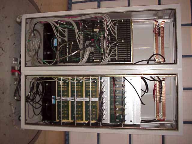
OF2FWBASE
Jun 28, 2001PCB - PCS Licensed Transmitter
Equipment Class
PCB - PCS Licensed Transmitter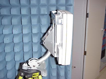
OF2WCSR30
Jun 28, 2001fixed wireless base station
Equipment Class
TNB - Licensed Non-Broadcast Station Transmitter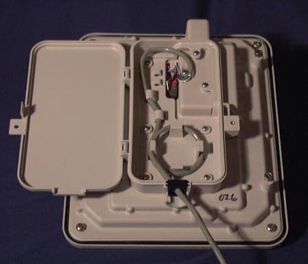
OF2CLRUDD3AXX
Jun 03, 2001PCS Wireless Access Network
Equipment Class
PCB - PCS Licensed Transmitter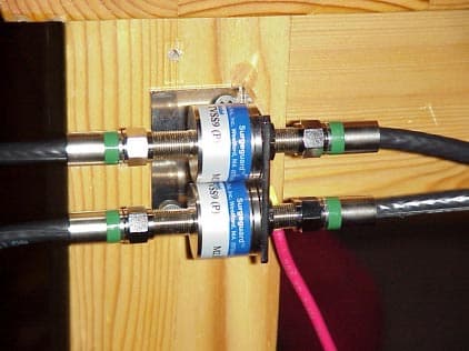
OF2PCSR30
Jun 03, 2001Fixed Wireless Base Station
Equipment Class
PCB - PCS Licensed Transmitter