OF2PCSR30Fixed Wireless Base Station
AT&T Wireless Services, Inc.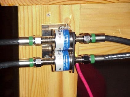
Click to zoom
Application Details
- Equipment Class
- PCB - PCS Licensed Transmitter
- Date of Grant
- Jun 03, 2001
- Application Purpose
- Original Equipment
- Date of Application
- Aug 02, 2000
- Equipment Note
- Fixed Wireless Base Station
- Frequency Range
- 1850.00000000 - 1990.00000000
- Company
- AT&T Wireless Services, Inc.
- Country
- United States
Documents & Files
Document Text
Text extracted from the exhibit documents filed with the FCC. Open a document above to read the original.
Users Manual
Chapter 13:User Manuals AT&T Wireless Services13-1 11576 Rev. 1.0 8/2/00 Chapter 13User Manuals Overview TheAT&T Local Service Customer Location User Manual is included in this chapter. AT&T Digital Broadband Customer Guide All Equipment, as defined in your AT&T Digital Broadband Services Agreement (the “Agreement”), is and shall remain the property of AT&T, and may be removed by AT&T at any time the service is disconnected, or at any reasonable time AT&T desires to make an exchange or modification of such Equipment as further outlined in the Agreement. 1 AT&T Digital Broadband: One Big Connection for Your Home Communication Needs Congratulations! You Made the Right Choice As an AT&T Digital Broadband customer, you have one company that serves all your home communication needs, with the convenience of one monthly bill and one number to call for customer service. It’s all yours as an AT&T Digital Broadband customer—high speed Internet access as well as local and long distance service—with the superior service you expect from AT&T. This booklet is your guide to the wide range of services available as an AT&T Digital Broadband customer. If you have questions or need support, AT&T Digital Broadband customer service representatives are ready to assist you. What’s Inside Getting Started . . . . . . . . . . . . . . . . . . . . . . . . . . . . . . . . . . . . . . . . . . . . . . . . . . . . . . . . . . 2 Calling Conveniences and Standard Features . . . . . . . . . . . . . . . . . . . . . . . . . . . . . . . . . . 6 Included Calling Features . . . . . . . . . . . . . . . . . . . . . . . . . . . . . . . . . . . . . . . . . . . . . . . . . 7 AT&T Provided Equipment . . . . . . . . . . . . . . . . . . . . . . . . . . . . . . . . . . . . . . . . . . . . . . . 18 AT&T Digital Broadband Customer Guide 2 Getting Started Here are the basics—from directions on placing calls and finding phone numbers to information on billing. Domestic Calls from Home • For calls within your own area code, just dial the 7- or 10-digit phone number. • For calls outside your area code, dial 1 + the area code + the 7-digit phone number. Operator-Assisted Calls To make a collect person-to-person, or operator-assisted call from anywhere within the United States, dial 1-800-CALL- AT T (1-800-225-5288) when you are away from home, or simply dial 0 from home. Service Additions If you would like additional services, AT&T Digital Broadband representatives are ready to assist you at 1-877-ATT-DGTL (1-877-288-3485). International Calls from Home • To place the call yourself, dial 011+ the country code + the phone number • If you don’t know the country code, or wish to have an AT&T Operator place the call for you, simply dial 0. Looking for answers to questions about your high speed Internet access or phone service? Look no further. If this guide doesn’t address all your questions, our customer service representatives are available to help you with answers or troubleshooting. We have all the information you may need, so give us a call. AT&T Digital Broadband Customer Service 1-877-ATT-DGTL (1-877-288-3485) 3 911 Emergency Calls For emergency police, fire, or medical assistance: 1. Dial 911. If 911 is not available, dial 0. 2. Follow the 911 operator’s instructions. You can dial 911 free of charge from any phone. Note:911 should be used only in emergency situations in which there is immediate danger to life, health, or property. For non-emergency situations, please contact the police, fire department, or medical authorities at the number listed in your phone book, or call Directory Assistance. AT&T 00 Info Directory Assistance • Simply dial 00 from home to find any listed number in the U.S., whether it’s local or long distance, even when you don’t have the exact name or location. • When you’re away from home, dial 1-800-CALL-ATT, follow the prompts, and use your CALL ATT Calling Card or major credit card for billing. Trying to find a friend’s new home phone number or the number for the hotel where you’re staying on your business trip? Here’s where you’ll find the assistance you need. AT&T Digital Broadband Customer Guide 4 Calls Away from Home: Calling Card and Credit Card Calls Your CALL ATT™ Calling Card can be used for all calls, not just long distance. If you don’t have a CALL ATT™ Calling Card, or if you’d like to order additional cards, call 1-877- ATT-DGTL (1-877-288-3485). There is no charge to receive the card. 1 To place a call with your CALL ATT™ Calling Card or credit card: 1. Dial 1-800-CALL-ATT (1-800-225-5288). 2. Listen for the AT&T tone, then press 1. 3. Listen for and follow the simple, step-by-step calling instructions. Here are some time-saving tips when using your CALL ATT™ Calling Card or credit card: • Press # to place the next call without hanging up. • Press #123 to leave a message if the line is busy or not answered. • Press*to correct a mistake when dialing. 1. When calling from your home, AT&T Digital Broadband supports only AT&T-branded calling cards. Currently, other telephone company calling cards are not supported by this service. These services make it easy to stay in touch. Whether you’re calling home to find out what you need to pick up at the grocery store or calling the office from the airport, you’re always within reach. 5 AT&T Digital Broadband - High Speed Internet Access AT&T Digital Broadband high speed Internet access offers the following: • “Always On” 1 access to the Internet, with no dialing, and no busy signals. • Browse the Web up to 12 times faster than typical modems. • Multiple Internet connections and phone calls on the same line at the same time. 2 • Share printers and files, or enjoy multiple player gaming with a compatible in-home network. PC Equipment Requirements The following are minimum customer PC requirements: • CPU Windows 95: Pentium class processor or higher Windows 98: Pentium class processor or higher • Memory Windows 95: 16 megabytes (MB) Windows 98: 32 megabytes …
Text truncated - open the document above for the full version.
Attestation Statements
Chapter 1:Attestation Statements AT&T Wireless Services1-1 11576 Rev. 1.0 8/2/00 Chapter 1Attestation Statements FCC R3 Type Acceptance Report 1-2AT&T Wireless Services 11576 Rev. 1.0 8/2/00
Cover Letter(s)
Chapter 3:Cover Letters AT&T Wireless Services3-1 11576 Rev. 1.0 8/2/00 Chapter 3Cover Letters Overview There are no cover letters for this submittal. FCC R3 Type Acceptance Report 3-2AT&T Wireless Services Solely for authorized persons having a need to know pursuant to Company Instructions11576 Rev. 1.0 8/2/00
Cover Letter(s)
AT&T Wireless Services Wireless Local Technologies Group PO Box 97059 Redmond, WA 98073-9759 FCC R3 Type Acceptance Report 11576 Revision 1.0 8/2/00 FCC R3 Type Acceptance Report -2AT&T Wireless Services Solely for authorized persons having a need to know pursuant to Company Instructions11576 Rev. 1.0 8/2/00 © 1995-2000 AT&T Wireless Services All rights reserved. For additional copies of this document, please contact: AT&T Wireless Services PO Box 97059 Redmond, WA 98073-9759 Telephone: 425-702-2767 Facsimile: 425-702-3941 Ask for FCC R3 Type Acceptance Report or 11576. Contents AT&T Wireless Servicesiii 11576 Rev. 1.0 8/2/00 Contents Contents. . . . . . . . . . . . . . . . . . . . . . . . . . . . . . . . . . . . . . . . . . . . . . . . . iii List of Figures . . . . . . . . . . . . . . . . . . . . . . . . . . . . . . . . . . . . . . . . . . . ix List of Tables. . . . . . . . . . . . . . . . . . . . . . . . . . . . . . . . . . . . . . . . . . . . xvii Chapter 1 Attestation Statements Chapter 2 Block Diagrams 2.1Block Diagrams. . . . . . . . . . . . . . . . . . . . . . . . . . . . . . . . . . . . . . . . . . . . 2-2 Chapter 3 Cover Letters Chapter 4 External Photographs 4.1Photographs of the R3 Indoor Unit . . . . . . . . . . . . . . . . . . . . . . . . . . . . 4-2 4.2Photographs of the R3 Outdoor Unit. . . . . . . . . . . . . . . . . . . . . . . . . . . 4-7 Chapter 5 ID Label/Location Information 5.1ID Label . . . . . . . . . . . . . . . . . . . . . . . . . . . . . . . . . . . . . . . . . . . . . . . . . . 5-2 5.2Location Information. . . . . . . . . . . . . . . . . . . . . . . . . . . . . . . . . . . . . . . . 5-3 Chapter 6 Internal Photographs 6.1Internal Photographs of the R3 Outdoor Unit. . . . . . . . . . . . . . . . . . . . 6-2 FCC R3 Type Acceptance Report ivAT&T Wireless Services 11576 Rev. 1.0 8/2/00 6.2Internal Photographs of the R3 Indoor Unit . . . . . . . . . . . . . . . . . . . . . 6-9 Chapter 7 Operational Description 7.1System Overview. . . . . . . . . . . . . . . . . . . . . . . . . . . . . . . . . . . . . . . . . . . 7-2 7.1.1PWAN General Description . . . . . . . . . . . . . . . . . . . . . . . . . . . . . 7-2 7.1.2PWAN Network Element Overview . . . . . . . . . . . . . . . . . . . . . . . . 7-2 7.1.3Wireless Network Element Deployment . . . . . . . . . . . . . . . . . . . . 7-4 7.1.4PWAN Airlink Profile . . . . . . . . . . . . . . . . . . . . . . . . . . . . . . . . . . . 7-5 7.1.5PWAN Telephony Functions . . . . . . . . . . . . . . . . . . . . . . . . . . . . . 7-6 7.1.6PWAN FAX/Modem VF Traffic Functions . . . . . . . . . . . . . . . . . . . 7-9 7.1.7PWAN High-Speed Data Functions . . . . . . . . . . . . . . . . . . . . . . . 7-9 7.1.8HSD Medium Access . . . . . . . . . . . . . . . . . . . . . . . . . . . . . . . . . 7-10 7.2Airlink Overview. . . . . . . . . . . . . . . . . . . . . . . . . . . . . . . . . . . . . . . . . . . 7-11 7.2.1PWAN Physical Layer Overview . . . . . . . . . . . . . . . . . . . . . . . . . 7-11 7.2.1.1Services Provided by the Physical Layer . . . . . . . . . . 7-13 7.2.2PWAN Airlink Overview . . . . . . . . . . . . . . . . . . . . . . . . . . . . . . . 7-13 7.2.2.1PWAN Implementation of OFDM . . . . . . . . . . . . . . . . 7-15 7.2.3PWAN Airlink Resource Allocation . . . . . . . . . . . . . . . . . . . . . . . 7-18 7.2.4PWAN Network Access Channel (NAC) Functional Description 7-19 7.2.4.1BC Definition . . . . . . . . . . . . . . . . . . . . . . . . . . . . . . . . 7-19 7.2.4.2CLC Definition . . . . . . . . . . . . . . . . . . . . . . . . . . . . . . 7-19 7.2.4.3UCAC Definition . . . . . . . . . . . . . . . . . . . . . . . . . . . . . 7-20 7.2.4.4SCAC Definition . . . . . . . . . . . . . . . . . . . . . . . . . . . . . 7-20 7.2.5PWAN Voice Traffic Channel (VTch) Functional Description . . . 7-21 7.2.5.1Associated Control Channel Functional Description . 7-21 7.2.6PWAN High-Speed Data Services . . . . . . . . . . . . . . . . . . . . . . . 7-21 7.2.6.1Basic Data Service Allocation Definition . . . . . . . . . . . 7-21 7.2.6.2PWAN Data Traffic Channel (DTch) Definition . . . . . . 7-22 7.2.6.3High-Speed Data Medium Access Control . . . . . . . . . 7-23 7.2.7Network Synchronization . . . . . . . . . . . . . . . . . . . . . . . . . . . . . . 7-23 Chapter 8 Parts List/Tune Up Information 8.1Parts List . . . . . . . . . . . . . . . . . . . . . . . . . . . . . . . . . . . . . . . . . . . . . . . . . 8-2 8.1.1R3 Outdoor Unit PCB . . . . . . . . . . . . . . . . . . . . . . . . . . . . . . . . . . 8-2 8.1.2R3 Indoor Unit PCB . . . . . . . . . . . . . . . . . . . . . . . . . . . . . . . . . . . 8-5 8.1.3R3 Indoor Unit 2-line Expansion PCB . . . . . . . . . . . . . . . . . . . . . . 8-8 8.1.4R3 Indoor Unit Lucent AC-DC Power Supply . . . . . . . . . . . . . . . . 8-9 8.1.5R3 Indoor Unit Panasonic AC-DC Power Supply . . . . . . . . . . . . 8-11 Contents AT&T Wireless Servicesv 11576 Rev. 1.0 8/2/00 8.1.6R3 Outdoor Unit Lucent DC-DC Power Module . . . . . . . . . . . . . 8-12 8.2Output Power Tuning Procedures. . . . . . . . . . . . . . . . . . . . . . . . . . . . 8-13 8.2.1Hardware Output Power Limiting Circuit . . . . . . . . . . . . . . . . . . 8-13 8.2.2Software Output Power Control . . . . . . . . . . . . . . . . . . . . . . . . . 8-15 8.2.3Manufacturing Calibration . . . . . . . . . . . . . . . . . . . . . . . . . . . . . 8-16 8.2.4Hardware Frequency vs Temperature Results . . . . . . . . . . . . . . 8-16 Chapter 9 RF Exposure 9.1RF Human Exposure - FDTD Analysis and SAR Testing . . . . . . . . . . 9-2 9.1.1Applicable FCC Rules . . . . . . . . . . . . . . . . . . . . . . . . . . . . . . . . . 9-2 9.1.2Test Configuration . . . . . . . . . . . . . . . . . . . . . . . . . . . . . . . . . . . . 9-2 9.1.2.1Modelling . . . . . . . . . . . . . . . . . . . . . . . . . . . . . . . . . . . 9-2 9.1.2.2SAR Testing . . . . . . . . . . . . . . . . . . . . . . . . . . . . . . . . 9-2 9.1.3Test Results . . . . . . . . . . . . . . . . . . . . . . . . . . . . . . . . . . .…
Text truncated - open the document above for the full version.
Cover Letter(s)
AT&T Wire le ss Se rvice s, Inc. Correspondence Reference Numbe r: 15594 731 Confirmation Numbe r: EA983379 Pursuant to Seciton 2.926(d) of the Commission’s rules, AT&T Wireless Services, Inc. respectfully amends the above-referenced equipment application to correct the equipment product code to remove the period (.) from the FCC ID. The FCC ID should read as follows: OF2PCSR30.
Cover Letter(s)
AT&T Wireless Ser vices, Inc. FCC ID OF2PCSR30 Correspondence Reference Number 15686 731 Confirmation Number EA98379 Date of Original Email 8/21/00 Response FCC Question 1.) Output appears to be 41.7 dBm EIRP (26.7 dBm peak + 15 dBi – 14.8 W EIRP). Filing is requesting for 4.0 W EIRP. Please verify EIRP to be listed on the Grant. We tested the absolute worse case scenario by manually disabling the software attenuators. Production units will have the software attenuators and hardware RF output limiting circuit in place and will never exceed 36 dBm avg. Therefore, we're asking for the grant to be 36 dBm or 4 watts EIRP average. Thanks, Keit h Peavler
External Photos
Chapter 4:External Photographs AT&T Wireless ServicesAT&T Proprietary (Restricted)4-1 Solely for authorized persons having a need 11576 Rev. 0.5 00/00/00to know pursuant to Company Instructions AT&T Project PCS Information Review Copy ++ 0/0/00 ++ Seq. X Chapter 4External Photographs Overview This section contains external photographs of the R3 Indoor Unit and the R3 Outdoor Unit. Contents 4.1Photographs of the R3 Indoor Unit . . . . . . . . . . . . . . . . . . . . . . . . . . 4-2 4.2Photographs of the R3 Outdoor Unit . . . . . . . . . . . . . . . . . . . . . . . . 4-7 FCC R3 Type Acceptance Report 4-2AT&T Proprietary (Restricted)AT&T Wireless Services Solely for authorized persons having a need AT&T Project PCS Informationto know pursuant to Company Instructions11576 Rev. 0.5 00/00/00 Review Copy ++ 0/0/00 ++ Seq. X 4.1Photographs of the R3 Indoor Unit The front face of the R3 Indoor Unit has an HB plastic decorative cover with a power LED inset as shown inFigure 4.1. The enclosure is a sheet metal formed rectangular box measuring approximately 16 3/4”x12 1/2”x3 1/2”. Figure 4.1Front of the R3 Indoor Unit Chapter 4:External Photographs AT&T Wireless ServicesAT&T Proprietary (Restricted)4-3 Solely for authorized persons having a need 11576 Rev. 0.5 00/00/00to know pursuant to Company Instructions AT&T Project PCS Information Review Copy ++ 0/0/00 ++ Seq. X Figure 4.2 shows the R3 Indoor Unit, which identifies both front and side ventilation. Figure 4.2Right-side view of the R3 Indoor Unit FCC R3 Type Acceptance Report 4-4AT&T Proprietary (Restricted)AT&T Wireless Services Solely for authorized persons having a need AT&T Project PCS Informationto know pursuant to Company Instructions11576 Rev. 0.5 00/00/00 Review Copy ++ 0/0/00 ++ Seq. X Figure 4.3 is a close-up view of the R3 Indoor Unit left side, which details the unit’s ventilation characteristics. Figure 4.3Side View of the R3 Indoor Unit Chapter 4:External Photographs AT&T Wireless ServicesAT&T Proprietary (Restricted)4-5 Solely for authorized persons having a need 11576 Rev. 0.5 00/00/00to know pursuant to Company Instructions AT&T Project PCS Information Review Copy ++ 0/0/00 ++ Seq. X Figure 4.4 shows the back-side of the R3 Indoor Unit. From left to right, the connections are as follows: • Power cable, standard 120 VAC input • Telco cabling, voice lines 1 and 2 • Telco cabling, voice lines 3 and 4 (expansion card used only when ordered by the customer) • RG-6 coaxial RF interconnection to R3 Outdoor Unit Figure 4.4 identifies the worst-case cabling configuration. Note:Figure 4.4 also shows the UL/FCC label location. Figure 4.4Rear view of the R3 Indoor Unit FCC R3 Type Acceptance Report 4-6AT&T Proprietary (Restricted)AT&T Wireless Services Solely for authorized persons having a need AT&T Project PCS Informationto know pursuant to Company Instructions11576 Rev. 0.5 00/00/00 Review Copy ++ 0/0/00 ++ Seq. X Figure 4.5 depicts the gas tube surge protector manufactured by NEXTEC. This protects the R3 Indoor Unit from indirect surges and transients that may flow on the coax to the R3 Indoor Unit. The coax provides DC voltage to the R3 Outdoor Unit, along with Ethernet connection. Figure 4.5R3 Surge Protector Chapter 4:External Photographs AT&T Wireless ServicesAT&T Proprietary (Restricted)4-7 Solely for authorized persons having a need 11576 Rev. 0.5 00/00/00to know pursuant to Company Instructions AT&T Project PCS Information Review Copy ++ 0/0/00 ++ Seq. X 4.2Photographs of the R3 Outdoor Unit The front face of the R3 Outdoor Unit has an HB plastic radome which connects to a metallic back frame. The radome shown inFigure 4.6, covers the antenna and measures approximately 12 inches by 14 inches. Figure 4.6Front View of the R3 Outdoor Unit Antenna FCC R3 Type Acceptance Report 4-8AT&T Proprietary (Restricted)AT&T Wireless Services Solely for authorized persons having a need AT&T Project PCS Informationto know pursuant to Company Instructions11576 Rev. 0.5 00/00/00 Review Copy ++ 0/0/00 ++ Seq. X Figure 4.7 shows the R3 Outdoor Unit back view which identifies the RG-6 coaxial cable connections. The RG-6 coaxial connections provide the Ethernet connection and DC power to the R3 Outdoor Unit from the R3 Indoor Unit. Figure 4.7Rear View of the R3 Outdoor Unit Chapter 4:External Photographs AT&T Wireless ServicesAT&T Proprietary (Restricted)4-9 Solely for authorized persons having a need 11576 Rev. 0.5 00/00/00to know pursuant to Company Instructions AT&T Project PCS Information Review Copy ++ 0/0/00 ++ Seq. X Figure 4.8 shows the R3 Outdoor Unit side view with the typical metallic mounting bracket. Figure 4.8Side View of the Outdoor Unit with Mounting Bracket
ID Label/Location Info
Chapter 5:ID Label/Location Information AT&T Wireless Services5-1 11576 Rev. 1.0 8/2/00 Chapter 5ID Label/Location Information Overview This section contains ID label and location information. Contents 5.1ID Label . . . . . . . . . . . . . . . . . . . . . . . . . . . . . . . . . . . . . . . . . . . . . . 5-2 5.2Location Information . . . . . . . . . . . . . . . . . . . . . . . . . . . . . . . . . . . . 5-3 FCC R3 Type Acceptance Report 5-2AT&T Wireless Services 11576 Rev. 1.0 8/2/00 5.1ID Label Figure 5.1 shows the FCC ID label that is located on both the R3 Outdoor Unit and the R3 Indoor Unit. The R3 Indoor Unit will be FCC certified , while the R3 Outdoor Unit will obtain an FCC Type Approval. Figure 5.1FCC ID Label for the R3 Indoor Unit Figure 5.2FCC ID Label for the R3 Outdoor Unit Chapter 5:ID Label/Location Information AT&T Wireless Services5-3 11576 Rev. 1.0 8/2/00 5.2Location Information Figure 5.3 shows the FCC ID label location on the backside of the R3 Outdoor Unit. Figure 5.3FCC ID Label Location on Antenna FCC R3 Type Acceptance Report 5-4AT&T Wireless Services 11576 Rev. 1.0 8/2/00 Figure 5.4 shows a close-up of the FCC ID label on the R3 Outdoor Unit. Note the FCC ID number. Figure 5.4Close-up of Label on R3 Outdoor Unit Chapter 5:ID Label/Location Information AT&T Wireless Services5-5 11576 Rev. 1.0 8/2/00 Figure 5.5 shows the FCC ID label location on the R3 Indoor Unit. Figure 5.5FCC ID Label Location on the R3 Indoor Unit FCC R3 Type Acceptance Report 5-6AT&T Wireless Services 11576 Rev. 1.0 8/2/00 Figure 5.6shows a close-up of the FCC ID label on the R3 Indoor Unit. Figure 5.6FCC Label Location on R3 Indoor Unit
ID Label/Location Info
Chapter 5:ID Label/Location Information AT&T Wireless Services5-1 11576 Rev. 1.0 8/2/00 Chapter 5ID Label/Location Information Overview This section contains ID label and location information. Contents 5.1ID Label . . . . . . . . . . . . . . . . . . . . . . . . . . . . . . . . . . . . . . . . . . . . . . 5-2 5.2Location Information . . . . . . . . . . . . . . . . . . . . . . . . . . . . . . . . . . . . 5-3 FCC R3 Type Acceptance Report 5-2AT&T Wireless Services 11576 Rev. 1.0 8/2/00 5.1ID Label Figure 5.1 shows the FCC ID label that is located on both the R3 Outdoor Unit and the R3 Indoor Unit. The R3 Indoor Unit will be FCC certified , while the R3 Outdoor Unit will obtain an FCC Type Approval. Figure 5.1FCC ID Label for the R3 Indoor Unit Figure 5.2FCC ID Label for the R3 Outdoor Unit Chapter 5:ID Label/Location Information AT&T Wireless Services5-3 11576 Rev. 1.0 8/2/00 5.2Location Information Figure 5.3 shows the FCC ID label location on the backside of the R3 Outdoor Unit. Figure 5.3FCC ID Label Location on Antenna FCC R3 Type Acceptance Report 5-4AT&T Wireless Services 11576 Rev. 1.0 8/2/00 Figure 5.4 shows a close-up of the FCC ID label on the R3 Outdoor Unit. Note the FCC ID number. Figure 5.4Close-up of Label on R3 Outdoor Unit Chapter 5:ID Label/Location Information AT&T Wireless Services5-5 11576 Rev. 1.0 8/2/00 Figure 5.5 shows the FCC ID label location on the R3 Indoor Unit. Figure 5.5FCC ID Label Location on the R3 Indoor Unit FCC R3 Type Acceptance Report 5-6AT&T Wireless Services 11576 Rev. 1.0 8/2/00 Figure 5.6shows a close-up of the FCC ID label on the R3 Indoor Unit. Figure 5.6FCC Label Location on R3 Indoor Unit
RF Exposure Info
Chapter 9:RF Exposure AT&T Wireless Services9-1 Solely for authorized persons having a need 11576 Rev. 1.0 8/2/00to know pursuant to Company Instructions Chapter 9RF Exposure Overview This chapter contains information as to how the product was determined to be compliant with FCC Part 24 subsection 24.51 Contents 9.1RF Human Exposure - FDTD Analysis and SAR Testing . . . . . . . . 9-2 9.2Summary and Conclusions . . . . . . . . . . . . . . . . . . . . . . . . . . . . . . . . 9-3 9.3Computer Hardware and Software Used for Performing Calculations . 9-4 9.42 FDTD Models . . . . . . . . . . . . . . . . . . . . . . . . . . . . . . . . . . . . . . . . 9-5 9.6FDTD Calculation of SAR in REMCOM Head and Shoulders Inhomogeneous Model . . . . . . . . . . . . . . . . . . . . . . . . . . . . . . . . . . 9-16 FCC R3 Type Acceptance Report 9-2AT&T Wireless Services 11576 Rev. 1.0 8/2/00 9.1RF Human Exposure - FDTD Analysis and SAR Testing 9.1.1Applicable FCC Rules FCC Subpart 24.51 - Applications for Type Approval of transmitters operating within the PCS region must determine that the equipment complies with IEEE C95.1-1991, “IEEE Standards for Safety Levels with Respect to Human Exposure to Radio Frequency Electromagnetic Fields, 3 kHz to 300 GHz” as measured using methods specified in IEEE C95.3 - 1991, “Recommended Practice for the Measurement of Potentially Hazardous Electromagnetic Fields - RF and Microwave.” 9.1.2Test Configuration RF human exposure configurations were setup, tested, and evaluated by the following independent laboratories for the original Remote Unit. The R3 is a revision of the original unit and utilizes the same antenna. Modifications were made to the antenna housing and radome, therefore, additional modelling was completed by Dr. William Guy. Due to the accuracy of correlation from the modelling to the SAR testing, AT&T feels that modelling of this product revision is adequate. 9.1.2.1 Modelling Modelling was performed on both Remote Units R1 and R3 by Bioelectromagnetics Consulting, 18122 60th Pl. N.E., Kenmore, Washington 98028, with Dr. William Guy as primary consultant, responsible for carrying out the FDTD numerical analysis of the near fields, far fields, and SAR distributions from the R3 Outdoor Unit. As primary consultant, additional responsibilities included the evaluation and analysis of the SAR data from the independent SAR measurement laboratories. 9.1.2.2 SAR Testing SAR testing performed on the original Remote Unit and correlated to the models by SAR testing Schmid & Partner Engineering AG (SPEAG), Staffelstrasse 8, 8045 Zurich, Switzerland, with Dr. Neils Kuster as the project director, who was responsible for carrying out measurements of the near and far fields from the RU Outdoor Unit and SAR distribution in homogeneous phantom head and a flat rectangular tissue models exposed to the antenna fields. Chapter 9:RF Exposure AT&T Wireless Services9-3 11576 Rev. 1.0 8/2/00 SARTest Ltd., Oakfield Laboratories, Cudworth Lane, Newdigate, Surrey RH5 5DR. UK., with M.I. Manning as project director, who was responsible for carrying out measurements of the near and far fields from the RU Outdoor Unit and SAR distribution in a heterogeneous phantom head model and a flat heterogeneous rectangular tissue model exposed to the antenna fields. 9.1.3Test Results Bioelectromagnetics Consulting compiled and correlated all data pertaining to FCC Subpart 24.51, and found the product to be compliant with this rule part. The results of the SAR calculations are summarized inTable 9.1. 9.2Summary and Conclusions The FDTD method was used to calculate the far field antenna patterns and near electric and magnetic fields for the AT&T R3 Ball PCS antenna radiating in free space for an input power of 158.5 mW split evenly between two coaxial antenna input feeds. The antenna patterns and gain closely agreed with the antenna manufacturers measured Table 9.1Summary and Comparison of Calculated and Measured Maximum SARs to FCC MPL for Various Tissue Models Exposed to AT&T RU Antenna. Model Peak SAR (W/kg) 1 Gram Avg SAR (W/kg) dB from FCC MPL e.i.r.p. = 2.0 We.i.r.p. = 3.0 We.i.r.p. = 4.0 W SPEAG Head, nose over array 0.5750.341-9.71-7.96-6.71 SPEAG Head, nose over right patch 4.151.67-2.81-1.060.186 SPEAG Head, nose over left patch 2.321.16-4.40-2.65-1.40 REMCOM Head, nose over array 1.320.229-11.44-9.69-8.44 FCC R3 Type Acceptance Report 9-4AT&T Wireless Services 11576 Rev. 1.0 8/2/00 values. The SPEAG (Schmid & Partner, Engineering AG (SPEAG), Staffelstrasse 8, 8045 Zurich, Switzerland) homogeneous head model and the REMCOM inhomogeneous head model used in the the previous AT&T RU Antenna study as reported in January 12, 1999 were also used in this study. The finite difference time domain (FDTD) technique was used to calculate the near and far fields and induced SAR patterns in exposed tissues from the antenna. The FDTD technique is currently the most popular theoretical method of choice for analyzing the safety and compliance of wireless technology devices with human RF exposure MPLs. Peak and 1 gram average SARs for various computer tissue phantoms consisting of homogeneous and inhomogeneous human head models exposed to the AT&T R3 antenna were calculated. The results in Table 9.1show that the worst case scenario is exposure of the head with the nose in contact with the radome and centered over the lower right patch resulting in an exposure of 0.186 dB above the FCC MPL of 1.6 W/kg when the antenna is operating with 158.5 mW input corresponding to an e.i.r.p. of 4 watts. It is highly unlikely that such an exposure would last for the 30 minute averaging time specified by the FCC and most likely would only be momentary if it ever occurred in practice. For example an 18-second exposure under these conditions would result in SARs nearly 20 dB below the FCC MPL. As expected the exposure of the more life-like inhomogeneous head model results in SARs lower than obtained from the worst case homogeneou…
Text truncated - open the document above for the full version.
Test Report
Chapter 11:Test Report AT&T Wireless Services11-1 11576 Rev. 1.0 8/2/00 Chapter 11Test Report Overview This section includes the test report and data showing compliance with all applicable technical standards. Contents 11.1Test Methodology . . . . . . . . . . . . . . . . . . . . . . . . . . . . . . . . . . . . . . 11-2 11.2RF Characterization Test Results . . . . . . . . . . . . . . . . . . . . . . . . . 11-31 11.3Electromagnetic Compatibility Test Results. . . . . . . . . . . . . . . . . 11-57 11.4R3 Outdoor Unit Specifications . . . . . . . . . . . . . . . . . . . . . . . . . 11-133 FCC R3 Type Acceptance Report 11-2AT&T Wireless Services 11576 Rev. 1.0 8/2/00 11.1 Test Methodology This section describes the test methodology used to validate the performance of the AT&T Wireless Services R3 Remote Unit (R3), which consists of the R3 Indoor Unit and the R3 Outdoor Unit, against the applicable requirements of FCC Part 2, 15, and Part 24. 11.1.1 Introduction The purpose of this chapter is to present the test methodology used to verify FCC regulatory compliance of the R3. Throughout this document, all depictions of test configurations utilize a common set of interfaces. These interfaces are described in detail in Chapter 7, “Operational Description” of this document. The name and purpose of each interface is summarized inTable 11.1 below: Table 11.1 PWAN Interface Definitions 11.1.2 Equipment Classification The AT&T R3 Outdoor Unit is designed to be mounted to a building, therefore it is classified as a “fixed station” as defined in Subpart 24.5 of the FCC Rules and Regulations. Consequently, the output power limitations associated with Base Stations described under FCC Subpart 24.232(a) were applied to this unit. However, it should be noted that the Effective Isotropic Radiated Power (EIRP) of the R3 will not exceed 4 watts EIRP average power. Interface IDDescription T InterfaceTerminal interface to R3 A InterfaceAir interface between R3 and Base Station radio equipment P InterfaceInterface between Base Station radio equipment and Base Station control Csw InterfaceInterface that provides public switched telephone network (PSTN) connectivity for call processing Chapter 11:Test Report AT&T Wireless Services11-3 11576 Rev. 1.0 8/2/00 11.1.3 Remote Unit RF Frequency Stability vs. Temperature Test Methodology 11.1.3.1 Applicable FCC Rules Parts FCC Subpart 2.995 - Measured over the temperature range of -30 to +…
Text truncated - open the document above for the full version.
Contact Information
Applicant
Douglas I Brandon(Vice President)
Technical Contact
AT&T Wireless Services, Inc.Keith Peavler
[email protected]425-702-2914
1150 Connecticut Ave NW, 4th Floor · Redmond, Dist of Columbia · United States
Non-Technical Contact
AT&T Wireless Services, Inc.Lisa M Volpe
[email protected]202-416-6519
Technical Specifications
| # | Rule Parts | Frequency Range | Power Output | Emission | Tolerance |
|---|---|---|---|---|---|
| 1 | 24 | 1.85 GHz - 1.99 GHz | 4 W | 1M00W7W | 0.1000000000 ppm |
Other Applications from AT&T Wireless Services, Inc.
OF2FWBASE15PCS
Dec 06, 2001fixed wireless base station
Equipment Class
PCB - PCS Licensed Transmitter
OF2FWBASE15WCS
Jul 22, 2001fixed wireless base station
Equipment Class
TNB - Licensed Non-Broadcast Station Transmitter
OF2FWBASE
Jun 28, 2001PCB - PCS Licensed Transmitter
Equipment Class
PCB - PCS Licensed Transmitter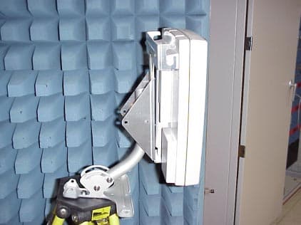
OF2WCSR30
Jun 28, 2001fixed wireless base station
Equipment Class
TNB - Licensed Non-Broadcast Station Transmitter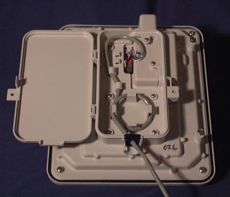
OF2CLRUDD3AXX
Jun 03, 2001PCS Wireless Access Network
Equipment Class
PCB - PCS Licensed Transmitter