OHRID20Motion Sensor
MS Sedco, Inc.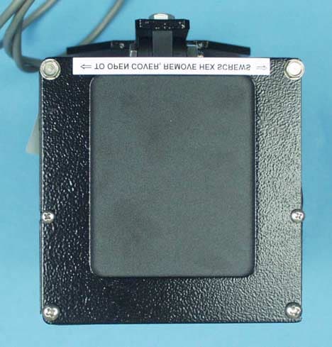
Click to zoom
Application Details
- Equipment Class
- FDS - Part 15 Field Disturbance Sensor
- Date of Grant
- Oct 10, 2001
- Application Purpose
- Original Equipment
- Date of Application
- Oct 10, 2001
- Equipment Note
- Motion Sensor
- Frequency Range
- 10524.00000000 - 10525.00000000
- Company
- MS Sedco, Inc.
- Country
- United States
Documents & Files
Document Text
Text extracted from the exhibit documents filed with the FCC. Open a document above to read the original.
Users Manual
- 1 - ID20 Industrial Door ActivatorID20 Industrial Door Activator INSTALLATION INSTRUCTIONS Section 1 General Description The Model ID20 is a motion sensor/vehicle detector designed to trigger the operation of an automatic industrial door. The main difference between the ID20 and other motion sensors is that the ID20 will respond to motion moving in only one direction. The ID20 generates a very low power microwave beam aimed to cover the same area normally covered by one or more loop detector systems. It is less expensive to install and less susceptible to damage and malfunction from ice, salt and heavy vehicular traffic. The ID20 has an approximate pattern size of 18.5 feet wide at 60 feet long from the unit. The pattern is adjustable by turning the range potentiometer mounted on the PC board (see pattern drawing— Figure # 2). The ID20 operates on much the same principle that police radar uses. These units transmit a low power microwave signal, some of which is reflected by a moving target, such as a forklift or truck. This received signal goes through a Doppler shift, a slightly different frequency than was transmitted. Larger vehicles, such as semi-trucks, reflect more energy than automobiles and can be detected at further distances. Since the ID20 uses microwave signals as its means of detecting a moving target, it is not affected by air motion, temperature and humidity changes, or high frequency sounds. Section 2 Installation The ID20 vehicle sensor can be mounted for side- fire or overhead detection. The typical mounting height is 12 to 18 feet. The sensor is mounted with 2 lag bolts through 2 - ½” prepunched mounting holes. To remove the fastening bracket from the sensor, take out the ¼-20 bolt holding the bracket to the hinge. Using the bracket as a template for locating screw holes, drill the pole or band the bracket and refasten the sensor to the bracket with the ¼-20 bolt removed earlier. Wiring - (see wiring diagram—Figure #1) Operating voltage is 12 to 24V AC or DC and is usually supplied through a transformer. Current consumption of the unit is 0.075 Amps @ 24VDC NOTE: Transformer is included. Remove four (4) hex head, self tapping machine screws, two on each end of the sensor, allowing the enclosure cover to be lifted off, exposing the terminal strip. When wiring the ID20, apply power to terminals 1 and 2. The relay contacts on terminals 4 and 5 are normally open (N.C.) and terminals 5 and 6 are normally closed (N.O.). NOTE: When power is applied, allow 30 seconds of warm-up before testing the sensor. MS Sedco suggests the use of 4 conductor cable, 18 to 22 gauge conductor size, 3 / 16 ” to 5 / 16 ” cable O.D. If 22 gauge wire is used to connect the ID20, add the following: 1.Install a 24V, 40VA transformer, instead of the 12V, 10VA transformer that is furnished, for long wire runs (300 feet or more). 2.Seal the wire fitting with sealant. This connector is designed for wire with a jacket between 3 / 16 ” and 5 / 16 ” OD to make a good fit in the power grip connector. 3.No wire larger than 18 gauge can be used. The terminal block is not large enough to accept wire larger than this. Alignment Align the ID20 motion by adjusting the range potentiometer and the aiming angle. The range potentiometer allows the detection pattern to be expanded or contracted to cover the traffic lane. The hinge adjustment allows the sensor detection pattern to be aimed toward the desired detection zone. To adjust the sensor’s head angle, loosen the 8-32 lock screw and the ¼-20 hinge screw. This allows vertical movement of the ID20 motion sensor. - 2 - When the pattern adjustment is completed, ensure that all bolts and screws are tightened. Operation An LED is located on the main circuit board and provides a visual indication as to how the unit is operating. The wiring and adjustment specifications (Figure 1) show the location of this LED indicator. The LED will illuminate when the relay has changed state in response to motion. Section 3 System Inspection and Instructions *****EXTREMELY IMPORTANT***** After final set-up, test the unit(s) completely to be sure that it is functioning properly, as specified in this manual. After the installation and operational check of the system: 1. Instruct the owner of door system operation and how to test it. This should be checked on a daily basis. 2.Instruct the owner on what to do if the door or any of its components become damaged. 3.Strongly recommend to the owner that the complete entry be inspected twice a year as part of the service agreement. Note: The manufacturer is not responsible for any radio or TV interference caused by unauthorized modifications to this equipment. Such modifications could void the user’s authority to operate the equipment. Section 4 Technical Data Model..............................ID20 Frequency......................10.525 GHz Detection Pattern............Adjustable Range (see Fig. 2 for pattern size) Detection Angle..............Adjustable, Horizontal & Vertical Response Time..............0.150 seconds Hold Time.......................0 to 5 seconds Power Requirements......12 to 24V AC or DC Current Consumption.....0.075 Amp @ 24V DC Relay Contacts...............1 Form C, rated at 3 Amp Mounting.........................Heavy-duty bracket, predrilled & slotted. Temperature...................-35°F to 165°F (-35°C to 74°C) Weight............................3.5 lbs. (1.6 kg) Size................................7" x 4” x 4” 17.8cm x 10.2cm x 10.2cm Color/Enclosure..............Aluminum Pattern............................16° beam width (at 60’ the pattern is approx. 18.5’ wide) Section 5 Warranty MS Sedco guarantees this product to be free from manufacturing defects for one year from date of installation. Unless MS Sedco is notified of the date of installation, the warranty will be in effect for one year from the date of shipment from our factory. If, during the first year, this motion detector or support device fails to operate and h…
Text truncated - open the document above for the full version.
External Photos
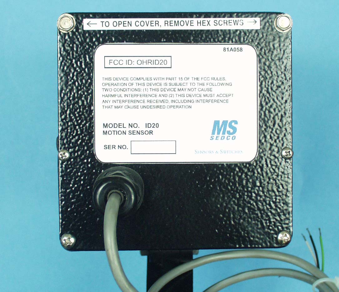
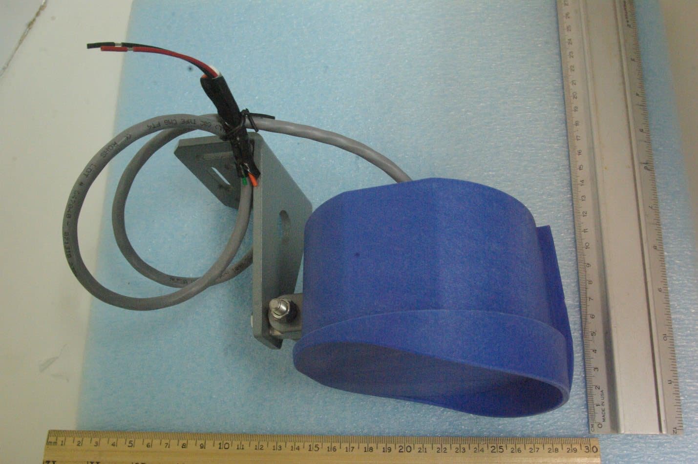
External Front View External, Left Side View External Top View External Right Side View External Back View
Internal Photos
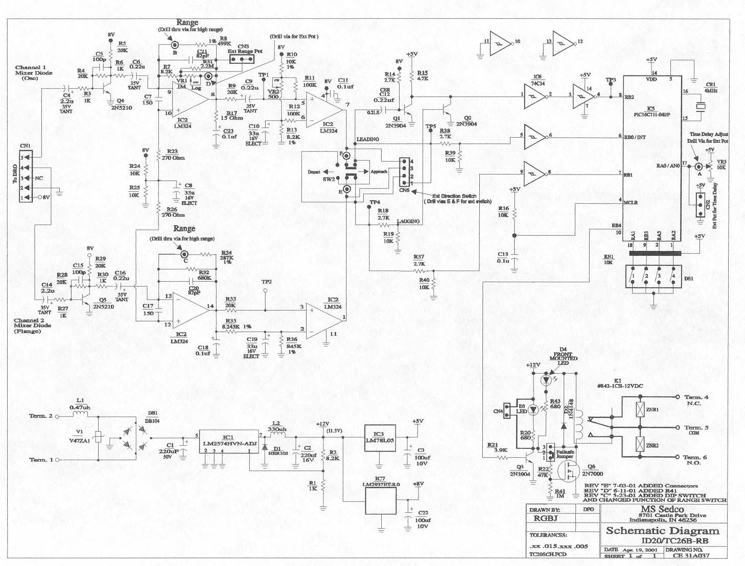
Internal Top View (Instructions) Internal Top, Circuit Board Internal Horn Internal Right Side Internal Left Side Internal Circuit Board, Track Side
Test Report
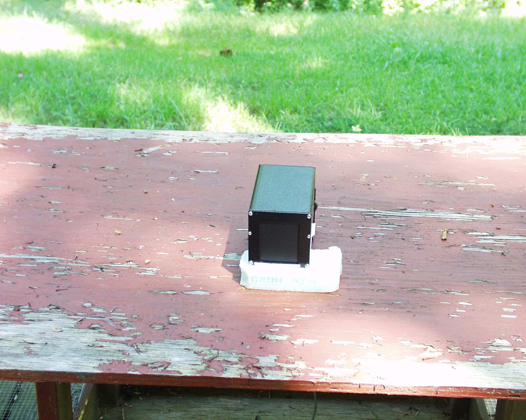
ENGINEERING STATEMENT For Certification of MS Sedco Model No: ID20 FCC ID: OHRID20 I am an Electronics Engineer, a principal in the firm of Hyak Laboratories, Inc., Springfield, Virginia. My education and experience are a matter of record with the Federal Communications Commission. Hyak Laboratories, Inc. has been authorized by MS Sedco to make measurements on the ID20 field disturbance detector. These tests made by me or under my supervision in our Springfield laboratory. Test data and documentation required by the FCC are included in this report. ______________________________ Rowland S. Johnson Dated: September 25, 2001 A. INTRODUCTION The following data are submitted to establish compliance of the ID20 transceiver in accordance with Part 2, Subpart J of the FCC Rules. The ID20 detector is a microwave field disturbance sensor for use only within a building or to open a building door and complies with 15.245(1)(i). B. RESULTS SUMMARY The ID20 detector met all the applicable requirements of Part 15.245. C. DESCRIPTION OF RADIATED SPURIOUS MEASUREMENT FACILITIES A description of the Hyak Laboratories’ radiation test facility is a matter of record with the FCC. The facility was accepted for radiation measurements on October 1, 1976 and is currently listed as an accepted site. D. FIELD STRENGTH MEASUREMENTS OF SPURIOUS RADIATION The procedures of ANSI 63.4 (1992) were followed. Field intensity measurements of radiated spurious emissions from the ID20 detector were made with a Tektronix 494P spectrum analyzer with external mixers using Polarad CA-L or CA-S or EMCO 3115 or EMCO 3116 horns. The transmitter was located in an open field 3 meters from the test antenna. Supply voltage was a terminal voltage under load of 18 Vdc. The transmitter and test antennae were arranged to maximize pickup. Both vertical and horizontal test antenna polarization were employed. Measurements were made from the lowest frequency generated within the unit (10.5 GHz), to the fifth harmonic (52.2 GHz) per FCC Rules 15.33(a)(2). Data after application of antenna factors and line loss corrections are shown in Table 1. 2 TABLE 1 RADIATED SPURIOUS EMISSIONS Measured at 3 meters PART 15(C) PARA. 15.245 Frequency Frequency To Which of Meter Antenna Field 1 Tuned Emission Reading Factor Intensity FCC Limit dB to __(GHz)__ __(GHz)_ _(dBm)_ __(dB)_ dBu @ 3m dBu @ 3m to Limit 10.525 10.524 -30.7 42.8 119.1 128 - 8.9 10.525 21.048 -65.3* 44.2 85.9 88 - 2.1 10.525 31.573 -70.4* 46.9 83.5 88 - 4.5 1) dBu = dBm + antenna factor + 107 * Measured @ 1 m, extrapolated to 3 m. All other spurious were below FCC limit or measurement system noise to the fifth harmonic. 3
Contact Information
Applicant
Andrew Kaffenberger(Director of Procurement)
Test Firm
Hyak Laboratories, Inc.Rowland Johnson
703-451-1188
Technical Specifications
| # | Rule Parts | Frequency Range | Power Output |
|---|---|---|---|
| 1 | 15.245 | 10.52 GHz - 10.53 GHz | - |
Other Applications from MS Sedco, Inc.
OHRVPR
Sep 24, 2023Field Disturbance Sensor
Equipment Class
FDS - Part 15 Field Disturbance Sensor
OHRS-TRX
Apr 10, 2012SPECTRUM TRANSCEIVER
Equipment Class
DXX - Part 15 Low Power Communication Device Transmitter
OHRS-COR
Apr 01, 2012CLEARPATH SPECTRUM COORDINATOR
Equipment Class
DXX - Part 15 Low Power Communication Device Transmitter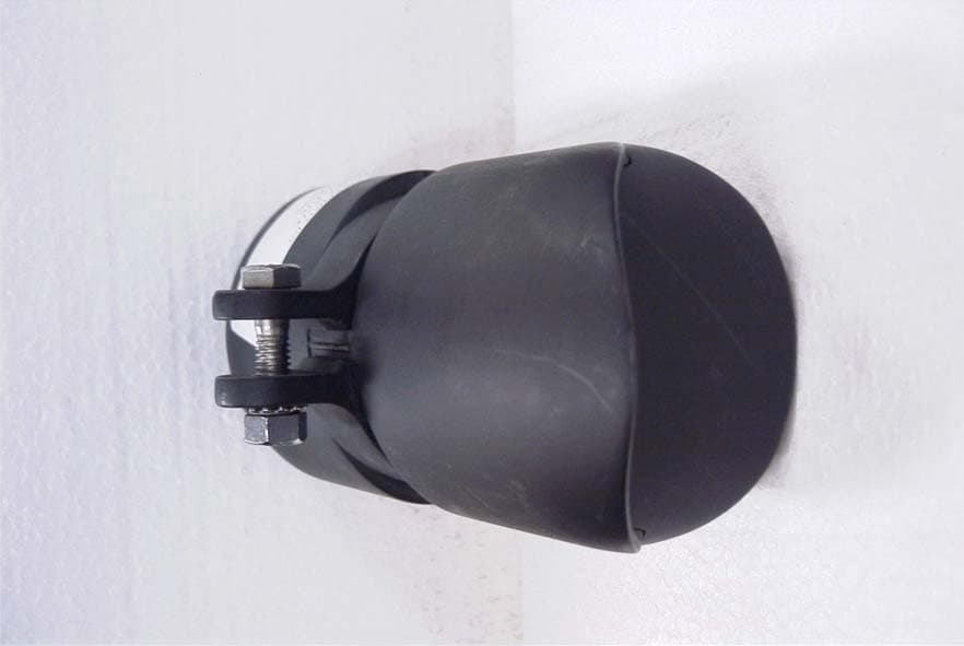
OHRWALK
Nov 06, 2006Pedestrian Sensor
Equipment Class
FDS - Part 15 Field Disturbance Sensor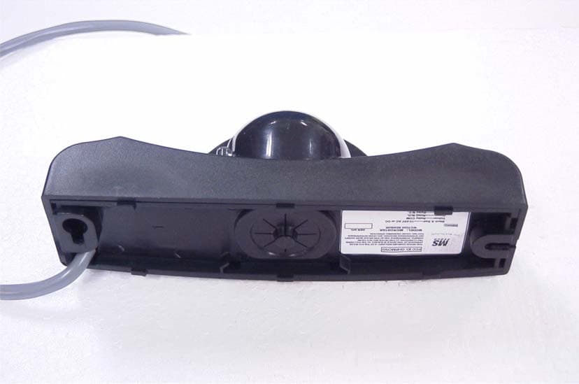
OHRMICRO
Oct 29, 2006MOTION SENSOR
Equipment Class
FDS - Part 15 Field Disturbance Sensor