OHRS-TRXSPECTRUM TRANSCEIVER
MS Sedco, Inc.
Click to zoom
Application Details
- Equipment Class
- DXX - Part 15 Low Power Communication Device Transmitter
- Date of Grant
- Apr 10, 2012
- Application Purpose
- Original Equipment
- Date of Application
- Apr 10, 2012
- Equipment Note
- SPECTRUM TRANSCEIVER
- Frequency Range
- 2425.00000000 - 2480.00000000
- Company
- MS Sedco, Inc.
- Country
- United States
Documents & Files
Document Text
Text extracted from the exhibit documents filed with the FCC. Open a document above to read the original.
Users Manual
8701 Castle Park Drive Indianapolis, Indiana 46256 Telephone: (800) 842-2545/(317) 842-2545 www.mssedco.com [email protected] Page 1 S-TRXv0312 Section 1 General Description ClearPath Spectrum radio control transceivers provide reliable activation of any automatic door, and feature several industry firsts. ClearPath Spectrum products feature digital two-way communication, increasing security and allowing users to pair transceivers to coordinators, and monitor battery power. With the ability to identify transceivers by location, optional SecureActivation will require users of the outside switch to be granted clearance before activation can occur. S-TRX = Spectrum Transceiver with 1020 Square Mounting Box - replaces CP/TX S-TRX-R4 = Spectrum Transceiver with 1025 Round Mounting Box - replaces CP/TX-R4 S-TRX-R6 = Spectrum Transceiver with 1030 Round Mounting Box - replaces CP/TX-R6 S-TRX-J = Spectrum Transceiver with 1010 Jamb Mounting Box - replaces CP/TX-J ClearPath Spectrum products operate at 2.4 GHz, making the wave length more than 5 times shorter than commonly-used frequencies. Shorter waves pass through cracks and barriers easier, and transmitters will continue to attempt to contact the coordinator until it receives an acknowledgement. Section 2 Basic Installation 1) Remove the 1/4-20 screw located in the bottom of the frame and separate the back plate from the frame (Fig.1). Secure the back plate in its intended location with at least 2 screws. WARNING: Mounting screws must be flush with the back plate to ensure proper assembly. FIGURE 1 (Front View: S-TRX Shown) (Rear View: S-TRX Shown) 2) Place coordinator into pairing mode. (See CS/COR coordinator instructions).. 3) Press PAIR button (Fig.2). FIGURE 2 Transmitter Circuit Board 4) Attach the push plate switch (purchased separately) to the mounting box frame with the 6-32 screws provided with the push plate switch (Fig.1). 5) Plug the 2-lead transmitter wire harness onto the COM (Common) and N.O. (Normally Open) contacts located on the push plate switch (Fig.3). FIGURE 3 ! BACK PLATE 1/4-20 SCREW PUSH PLATE SWITCH PUSH T O OPEN FRAME S-TRX (-R4, -R6, -J) Spectrum Transceiver with Surface Mouting Box INSTALLATION INSTRUCTIONS h Clear Pat ™ MICRO-SWITCH UL LISTED SPDT, Momentary RATED: 15A @ 125V AC COM N.C.N.O. Rubber Bellows Insert rubber bellows over spring on exterior switches for weather tight fit! BACK PLATE FRAME PUSH PLATE SWITCH LOCK LIP 1/4-20 SCREW TX PCB Battery Battery Battery 1 PAIR 8701 Castle Park Drive Indianapolis, Indiana 46256 Telephone: (800) 842-2545/(317) 842-2545 www.mssedco.com [email protected] Page 2 S-TRXv0312 6) Attach the mounting box frame to the back plate already mounted in its intended location (step 1) by placing the lock lip of the frame over the top of the back plate, pushing it down in a hinge-like motion (Fig.1). 7) Secure the mounting box frame to its back plate at the underside with the 1/4-20 screw supplied (Fig.1). NOTICE: This device complies with Part 15 of the FCC rules. Operation of this device is subject to the following two conditions: 1) This device may not cause harmful interference and 2) This device must accept any interference received, including interference that may cause undesired operation. Any changes or modifications not expressly approved by MS SEDCO could void the user's authority to operate this equipment. Section 3 Maintenance For best results, change the battery every 3 years, or as needed. To remove the current battery, use a small flat-head screwdriver, approaching from the PAIR button side of the pcb as shown (See Fig. 4). FIGURE 4 Transmitter Circuit Board ! S-TRX (-R4, -R6, -J) Spectrum Transceiver with Surface Mouting Box INSTALLATION INSTRUCTIONS hClearPat ™ Battery 1 PAIR Remove battery from this side.
External Photos
MS SEDCO CLEARPATH COORDINATOR HH HH PCB TOP HH PCB BOTTOM HH IN BOX HH WITH COVER ON HH WITH PUSH BUTTON LABEL ON HH WITH FCC LABEL ON BACK SIDE OF CASE
ID Label/Location Info
SEDCO c 020912 Rev. A.1 44A248 MS SEDCO Model #: S-TRX IC: 6775A-STRX FCCID: OHR S-TRX
Internal Photos
MS SEDCO CLEARPATH COORDINATOR HH HH PCB TOP HH PCB BOTTOM HH IN BOX HH WITH COVER ON HH WITH PUSH BUTTON LABEL ON HH WITH FCC LABEL ON BACK SIDE OF CASE
Test Report
FCC PART 15.249 AND IC RSS-210 TEST REPORT UNLICENSED INTENTIONAL RADIATOR Applicant MS SEDCO, INC. Address 8701 CASTLE PARK DRIVE INDIANAPOLIS IN 46256 USA FCC ID OHRS-TRX IC 6775A-STRX Model Number S-TRX Product Description SPECTRUM TRANSCEIVER Date Sample Received 12/19/2011 Date Tested 2/2/2012 Tested By John A. Day Approved By Mario R. de Aranzeta Report Number 2999AT11TestReport.doc Test Results PASS FAIL THE ATTACHED REPORT SHALL NOT BE REPRODUCED EXCEPT IN FULL WITHOUT THE WRITTEN APPROVAL OF TIMCO ENGINEERING, INC. Testing Certificate #0955-01 849 NW State Road 45 Newberry, FL 32669 USA Ph: 888.472.2424 or 352.472.5500 Fax: 352.472.2030 Email: [email protected] Website: www.timcoengr.com APPLICANT: MS SEDCO, INC. FCC ID: OHRS-TRX IC: 6775A-STRX REPORT #: M\MS_SEDCO\2999AT11\2999AT11TestReport.doc Page 2 of 13 Mdea 9.20.2007 TABLE OF CONTENT GENERAL REMARKS ................................................................................................................... 3 GENERAL INFORMATION ............................................................................................................ 4 EMC EQUIPMENT LIST ................................................................................................................ 5 TEST PROCEDURES .................................................................................................................... 6 RADIATION INTERFERENCE ....................................................................................................... 7 OCCUPIED BANDWIDTH ............................................................................................................. 8 BAND EDGE COMPLIANCE ......................................................................................................... 9 DUTY CYCLE ............................................................................................................................. 11 POWER LINE CONDUCTED INTERFERENCE ............................................................................ 13 APPLICANT: MS SEDCO, INC. FCC ID: OHRS-TRX IC: 6775A-STRX REPORT #: M\MS_SEDCO\2999AT11\2999AT11TestReport.doc Page 3 of 13 Mdea 9.20.2007 GENERAL REMARKS The attached report shall not be reproduced except in full without the written permission of Timco Engineering Inc. Summary The device under test does: fulfill the general approval requirements as identified in this test report not fulfill the general approval requirements as identified in this test report Attestations This equipment has been tested in accordance with the standards identified in this test report. To the best of my knowledge and belief, these tests were performed using the measurement procedures described in this report. All instrumentation and accessories used to test products for compliance to the indicated standards are calibrated regularly in accordance with ISO 17025 requirements. Certificate # 0955-01 I attest that the necessary measurements were made, under my supervision, at: Timco Engineering Inc. 849 NW State Road 45 Newberry, Fl 32669 Authorized Signatory Name: Mario de Aranzeta C.E.T. Compliance Engineer/ Lab. Supervisor Date: 2/15/2012 APPLICANT: MS SEDCO, INC. FCC ID: OHRS-TRX IC: 6775A-STRX REPORT #: M\MS_SEDCO\2999AT11\2999AT11TestReport.doc Page 4 of 13 Mdea 9.20.2007 GENERAL INFORMATION DUT Specification The test results relate only to the items tested. Applicable Standard Part 15.249 DUT Description SPECTRUM TRANSCEIVER FCC ID OHRS-TRX Model Number S-TRX Operating Frequency TX: 2425, 2450, 2475, 2480 RX: Same No. of Channels 4 Modulations Zigbee DUT Power Source 110–120Vac/50– 60Hz DC Power Battery Operated Exclusively Test Item Prototype Pre-Production Production Type of Equipment Fixed Mobile Portable Antenna Connector FCC Rules require that the antenna connector be unique. Test Facility Timco Engineering Inc. located at 849 NW State Road 45 Newberry, FL 32669 USA. Test Conditions Temperature: 26ºC Relative humidity: 50% Test Exercise The DUT was placed in continuous transmit mode of operation. Modifications None Test Supporting Equipment Supporting Device Manufacturer Model / FCC ID Serial Number N/A APPLICANT: MS SEDCO, INC. FCC ID: OHRS-TRX IC: 6775A-STRX REPORT #: M\MS_SEDCO\2999AT11\2999AT11TestReport.doc Page 5 of 13 Mdea 9.20.2007 EMC EQUIPMENT LIST Device Manufacturer Model Serial Number Cal/Char Date Due Date 3/10-Meter OATS TEI N/A N/A 12/20/10 12/20/10 3-Meter OATS TEI N/A N/A 02/05/09 02/05/12 Antenna: Passive Loop EMC Test Systems EMCO 6512 9706-1211 06/02/09 06/02/11 Frequency Counter HP 5385A 2730A03025 08/17/11 08/17/13 Frequency Counter HP 5352B 2632A00165 06/22/11 06/22/13 Digital Multimeter Fluke 77 43850817 09/09/11 09/09/13 Digital Multimeter Fluke FLUKE-77-3 79510405 06/13/11 06/13/13 Frequency Counter HP 5385A 3242A07460 06/22/11 06/22/13 Antenna: Active Loop ETS-Lindgren 6502 00062529 09/23/10 09/23/12 3-Meter Semi- Anechoic Chamber Panashield N/A N/A 05/10/10 Temperature Chamber Thermotron Corp. S1.2 Mini Max 25-1420-09 06/18/10 06/18/12 Analyzer Tan Tower Preamplifier HP 8449B-H02 3008A00372 11/21/09 10/28/13 Analyzer Tan Tower Quasi- Peak Adapter HP 85650A 3303A01690 11/22/09 10/28/13 Analyzer Tan Tower RF Preselector HP 85685A 3221A01400 11/21/09 10/28/13 Analyzer Tan Tower Spectrum Analyzer HP 8566B Opt 462 3138A07786 3144A20661 11/24/09 10/28/13 Antenna: Biconnical Eaton 94455-1 1057 05/31/11 05/31/13 Antenna: Log- Periodic Eaton 96005 1243 05/31/11 05/31/13 APPLICANT: MS SEDCO, INC. FCC ID: OHRS-TRX IC: 6775A-STRX REPORT #: M\MS_SEDCO\2999AT11\2999AT11TestReport.doc Page 6 of 13 Mdea 9.20.2007 TEST PROCEDURES Radiation Interference: ANSI C63.4-2003 using a spectrum analyzer, a preselector, a quasi- peak adapter, and an appropriate antenna. The analyzer was calibrated in dB above a microvolt at the output of the antenna. The resolution bandwidth was 100 kHz with an appropriate sweep speed and the video bandwidth was 300 kHz up to 1 GHz and 1 MHz with a video BW of 3 MHz…
Text truncated - open the document above for the full version.
Contact Information
Applicant
Andrew Kaffenberger(Director of Procurement)
Test Firm
Timco Engineering, Inc.Bruno Clavier
Technical Specifications
| # | Rule Parts | Frequency Range | Power Output |
|---|---|---|---|
| 1 | 15C | 2.42 GHz - 2.48 GHz | - |
Other Applications from MS Sedco, Inc.
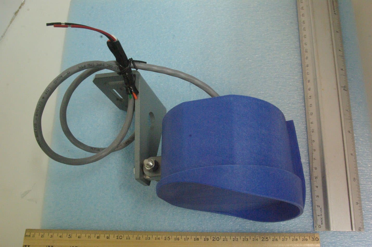
OHRVPR
Sep 24, 2023Field Disturbance Sensor
Equipment Class
FDS - Part 15 Field Disturbance Sensor
OHRS-COR
Apr 01, 2012CLEARPATH SPECTRUM COORDINATOR
Equipment Class
DXX - Part 15 Low Power Communication Device Transmitter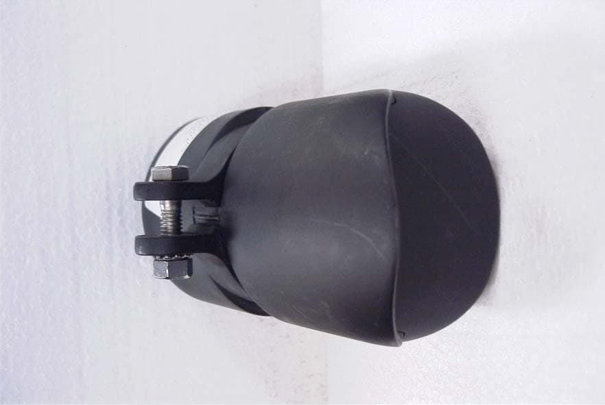
OHRWALK
Nov 06, 2006Pedestrian Sensor
Equipment Class
FDS - Part 15 Field Disturbance Sensor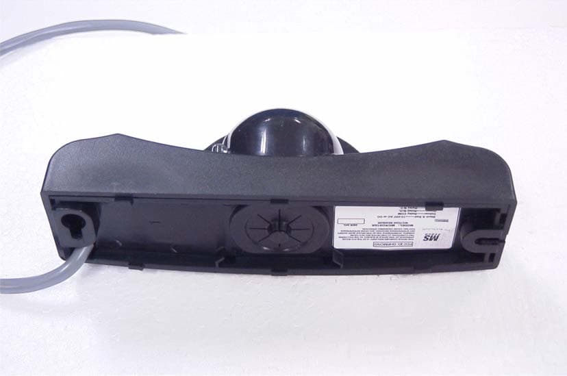
OHRMICRO
Oct 29, 2006MOTION SENSOR
Equipment Class
FDS - Part 15 Field Disturbance Sensor
OHRCP-TXHH
Dec 10, 2003CP/TX DUAL FREQUENCY R/C TRANSMITTER
Equipment Class
DSC - Part 15 Security/Remote Control Transmitter