OHRS-CORCLEARPATH SPECTRUM COORDINATOR
MS Sedco, Inc.
Click to zoom
Application Details
- Equipment Class
- DXX - Part 15 Low Power Communication Device Transmitter
- Date of Grant
- Apr 01, 2012
- Application Purpose
- Original Equipment
- Date of Application
- Apr 01, 2012
- Equipment Note
- CLEARPATH SPECTRUM COORDINATOR
- Frequency Range
- 2425.30000000 - 2480.00000000
- Company
- MS Sedco, Inc.
- Country
- United States
Documents & Files
Document Text
Text extracted from the exhibit documents filed with the FCC. Open a document above to read the original.
Users Manual
8701 Castle Park Drive Indianapolis, Indiana 46256 Telephone: (800) 842-2545/(317) 842-2545 www.mssedco.com [email protected] Page 1 S-CORv0312 Section 1 General Description The ClearPath Spectrum Coordinator functions in a similar role to traditional wireless system receiver and timing modules, and feature several industry firsts. ClearPath Spectrum products feature digital two-way communication, increasing security and allowing users to pair transmitters to coordinators, identify the transmitter’s location, and monitor battery power. Optional SecureActivation will require users of the outside switch to be granted clearance before activation can occur. ClearPath Spectrum coordinators feature two outputs with programmable time delay. ClearPath Spectrum products operate at 2.4 GHz, making the wave length more than 5 times shorter than commonly-used frequencies. Shorter waves pass through cracks and barriers easier, and transmitters will continue to attempt to contact the coordinator until it receives an acknowledgement. Section 2 Basic Installation The physical placement of the CS/COR is typically in the door operator housing area since the power supply and operator control are already there. Section 3 Technical Data Model.................................. ClearPath Spectrum™ S-COR Input Power......................... 12-24V AC or DC Output Contacts.................. Form C Relay 1 Contact Rating....... 3A:24V AC Relay 2 Contact Rating....... 1A:24V AC Temperature Rating........... -22°F to 158°F (-30°C to 70°C) Weight................................. 0.25 lbs. Physical Size....................... 3 3/4"L x 2 1/4"W x 1"H ! Spectrum Coordinator INSTALLATION INSTRUCTIONS S-COR hClearPat ™ Note that Output 1 will typically be used to trigger an electronic locking device, while Output 2 will be used to activate an automatic door. FIGURE 1 Wiring Diagram 1 2 3 4 5 6 7 RED (+) 12-40V AC or DC GREEN (Relay 2 - N.O.) BLK (-) 12-40V AC or DC GREEN (Relay 2 - COM) WHT (Relay 1 - N.C.) BROWN (Relay 1 - COM) VIO (Relay 1 - N.O.) 12 GREENWHITE < > Battery 1 PAIR 8701 Castle Park Drive Indianapolis, Indiana 46256 Telephone: (800) 842-2545/(317) 842-2545 www.mssedco.com [email protected] Page 2 S-CORv0312 Section 4 Programming the Coordinator — Single Openings: Upon power up, the screen will read “MS Sedco: Press Select to Begin.” Press Select. The next screen will show “Opening Type.” The default is Single. Press Select to skip this step and move on, or to verify the selection, press the > key. The next screen should then show Single*, with the * indicating the current selection. Press Select to move to the next step, or < to move back to the original screen and press Select. The next screen will show “Channel Select.” Four channels are available, with the default being channel 1. In most cases, the channel will remain at the default, and the installer may press Select to skip the step, but should one wish to auto scan to the cleanest channel, or manually choose a different channel for greater efficiency if two openings are in close proximity, this can be accomplished by using the arrow keys. Note that in manual mode, the current channel selection will be indicated with an asterisk (*). The next screen will show “Pair Device.” THE COORDINATOR WILL ONLY RESPOND TO TRANSMITTERS THAT HAVE BEEN PAIRED. Use the arrow keys to choose the location of the transmitter. The available choices are Outside, Inside, and HH (hand held). Choose the appropriate location of the transmitter and press select. The screen will then show “Press Device Pair Button.” Press the PAIR button on the transmitter’s circuit board. (Note: for hand held transmitters, the cover must be removed to access the PAIR button.) Upon pressing the PAIR button, the screen should change to “IDxxxx Paired Press Select.” At the end of two minutes, if the coordinator has not received a pairing signal, the screen will read “Pair Failed Press Select.” In either case, the screen will give you an option to pair additional devices. When all devices have been paired, choose “No” or “Skip” to move on the next screen. The next screen will read “Add Setting.” This is the place where users can program additional features into the device. Five additional settings are available: HH Signal Range, Output Delay, SecureActivation, Ratchet Relay, and Unpair Devices. These are covered below: Output Delay – This controls the delay between output relays 1 and 2 and can be adjusted via the arrow keys. Remember, Output 1 is typically the locking device, and Output 2 is typically an automatic door. After adjusting time with the arrow keys, press Select to move on to the next step. SecureActivation – Many times an automatic door with wireless activation is installed after a security system is already in place. SecureActivation allows the outside transmitter to be integrated into the security system. When SecureActivation is turned on, the outside switch will not activate the door unless given clearance from the security system. There are two choices for On, Normal Open and Normal Close, depending on whether the circuit is normally open or normally closed. WARNING: The Security Clearance input requires a dry contact. Do not apply voltage! Ratchet Relay – If Ratchet Relay is turned on, the output 2 relay will remain closed until a second signal is received. HH Signal Range – ClearPath Spectrum devices transmit a much greater distance than other wireless products used in the automatic door industry. Since a hand-held transmitter is paired with multiple coordinators in a building, or with two buildings in closer proximity, the default HH Signal Range is set to Reduced, requiring a very strong signal for the hand-held transceiver to operate. If a hand-held transceiver will not be used with used with any openings nearby, the range can be expanded to “Normal” by using the arrow keys and pressing Select when Normal displays on the screen. UnPair Devices – Transmitter…
Text truncated - open the document above for the full version.
External Photos
COORDINATOR IN BOX WITH TOP COVER COORDINATOR WITH POWER AND CONTROL CABLES
Internal Photos
MS SEDCO CLEARPATH COORDINATOR COORDINATOR PCB TOP COORDINATOR PCB BOTTOM COORDINATOR AND DISPLAY PCB TOP COORDINATOR AND DISPLAY PCB BOTTOM COORDINATOR AND DISPLAY CONNECTED COORDINATOR AND DISPLAY IN BOX COORDINATOR IN BOX WITH TOP COVER COORDINATOR WITH POWER AND CONTROL CABLES
Test Report
FCC PART 15.249 AND IC RSS-210 TEST REPORT UNLICENSED INTENTIONAL RADIATOR Applicant MS SEDCO, INC. Address 8701 CASTLE PARK DRIVE INDIANAPOLIS IN 46256 USA FCC ID OHRS-COR IC 6775A-SCOR Model Number S-COR Product Description CLEARPATH SPECTRUM COORDINATOR Date Sample Received 12/19/2011 Date Tested 1/23/2012 Tested By John A. Day Approved By Mario de Aranzeta Report Number 2998AT11TestReport.doc Test Results PASS FAIL THE ATTACHED REPORT SHALL NOT BE REPRODUCED EXCEPT IN FULL WITHOUT THE WRITTEN APPROVAL OF TIMCO ENGINEERING, INC. Testing Certificate #0955-01 849 NW State Road 45 Newberry, FL 32669 USA Ph: 888.472.2424 or 352.472.5500 Fax: 352.472.2030 Email: [email protected] Website: www.timcoengr.com APPLICANT: MS SEDCO, INC. FCC ID: OHRS-COR REPORT #: M\MS_SEDCO\2998AT11\2998AT11TestReport.doc Page 2 of 13 Mdea 9.20.2007 TABLE OF CONTENT GENERAL REMARKS ................................................................................................................... 3 GENERAL INFORMATION ............................................................................................................ 4 EMC EQUIPMENT LIST ................................................................................................................ 5 TEST PROCEDURES .................................................................................................................... 6 RADIATION INTERFERENCE ....................................................................................................... 7 OCCUPIED BANDWIDTH ............................................................................................................. 8 BAND EDGE COMPLIANCE ......................................................................................................... 9 DUTY CYCLE ............................................................................................................................. 11 POWER LINE CONDUCTED INTERFERENCE ............................................................................ 13 APPLICANT: MS SEDCO, INC. FCC ID: OHRS-COR REPORT #: M\MS_SEDCO\2998AT11\2998AT11TestReport.doc Page 3 of 13 Mdea 9.20.2007 GENERAL REMARKS The attached report shall not be reproduced except in full without the written permission of Timco Engineering Inc. Summary The device under test does: fulfill the general approval requirements as identified in this test report not fulfill the general approval requirements as identified in this test report Attestations This equipment has been tested in accordance with the standards identified in this test report. To the best of my knowledge and belief, these tests were performed using the measurement procedures described in this report. All instrumentation and accessories used to test products for compliance to the indicated standards are calibrated regularly in accordance with ISO 17025 requirements. Certificate # 0955-01 I attest that the necessary measurements were made, under my supervision, at: Timco Engineering Inc. 849 NW State Road 45 Newberry, Fl 32669 Authorized Signatory Name: Mario de Aranzeta C.E.T. Compliance Engineer/ Lab. Supervisor Date: 2/15/2011 APPLICANT: MS SEDCO, INC. FCC ID: OHRS-COR REPORT #: M\MS_SEDCO\2998AT11\2998AT11TestReport.doc Page 4 of 13 Mdea 9.20.2007 GENERAL INFORMATION DUT Specification The test results relate only to the items tested. Applicable Standard Part 15.249 DUT Description CLEARPATH SPECTRUM COORDINATOR FCC ID OHRS-COR Model Number S-COR Operating Frequency TX: 2425, 2450, 2475, 2480 RX: Same No. of Channels 4 Modulations Zigbee DUT Power Source 110–120Vac/50– 60Hz DC Power Battery Operated Exclusively Test Item Prototype Pre-Production Production Type of Equipment Fixed Mobile Portable Antenna Connector FCC Rules require that the antenna connector be unique. Test Facility Timco Engineering Inc. located at 849 NW State Road 45 Newberry, FL 32669 USA. Test Conditions Temperature: 26ºC Relative humidity: 50% Test Exercise The DUT was placed in continuous transmit mode of operation. Modifications None Test Supporting Equipment Supporting Device Manufacturer Model / FCC ID Serial Number N/A APPLICANT: MS SEDCO, INC. FCC ID: OHRS-COR REPORT #: M\MS_SEDCO\2998AT11\2998AT11TestReport.doc Page 5 of 13 Mdea 9.20.2007 EMC EQUIPMENT LIST Device Manufacturer Model Serial Number Cal/Char Date Due Date 3/10-Meter OATS TEI N/A N/A Antenna: Passive Loop EMC Test Systems EMCO 6512 9706-1211 06/02/09 06/02/11 Frequency Counter HP 5385A 2730A03025 08/17/11 08/17/13 Frequency Counter HP 5352B 2632A00165 06/22/11 06/22/13 Digital Multimeter Fluke 77 43850817 09/09/11 09/09/13 Digital Multimeter Fluke FLUKE-77- 3 79510405 06/13/11 06/13/13 Frequency Counter HP 5385A 3242A07460 06/22/11 06/22/13 Antenna: Active Loop ETS-Lindgren 6502 00062529 09/23/10 09/23/12 3-Meter Semi- Anechoic Chamber Panashield N/A N/A Temperature Chamber Thermotron Corp. S1.2 Mini Max 25-1420-09 06/18/10 06/18/12 Analyzer Silver Tower Quasi-Peak Adapter HP 85650A 3303A01844 11/23/10 11/23/12 Analyzer Silver Tower RF Preselector HP 85685A 2926A00983 11/10/10 11/10/12 Analyzer Silver Tower Spectrum Analyzer HP 8566B Opt 462 3552A22064 3638A08608 11/10/10 11/10/12 Analyzer Tan Tower Preamplifier HP 8449B-H02 3008A00372 11/21/09 10/28/13 Analyzer Tan Tower Quasi-Peak Adapter HP 85650A 3303A01690 11/22/09 10/28/13 Analyzer Tan Tower RF Preselector HP 85685A 3221A01400 11/21/09 10/28/13 Analyzer Tan Tower Spectrum Analyzer HP 8566B Opt 462 3138A07786 3144A20661 11/24/09 10/28/13 Antenna: Biconnical Eaton 94455-1 1057 05/31/11 05/31/13 Antenna: Log- Periodic Eaton 96005 1243 05/31/11 05/31/13 APPLICANT: MS SEDCO, INC. FCC ID: OHRS-COR REPORT #: M\MS_SEDCO\2998AT11\2998AT11TestReport.doc Page 6 of 13 Mdea 9.20.2007 TEST PROCEDURES Radiation Interference: ANSI C63.4-2003 using a spectrum analyzer, a preselector, a quasi- peak adapter, and an appropriate antenna. The analyzer was calibrated in dB above a microvolt at the output of the antenna. The resolution bandwidth …
Text truncated - open the document above for the full version.
Contact Information
Applicant
Andrew Kaffenberger(Director of Procurement)
Test Firm
Timco Engineering, Inc.Bruno Clavier
Technical Specifications
| # | Rule Parts | Frequency Range | Power Output |
|---|---|---|---|
| 1 | 15C | 2.43 GHz - 2.48 GHz | - |
Other Applications from MS Sedco, Inc.
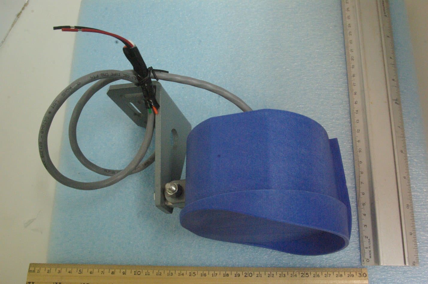
OHRVPR
Sep 24, 2023Field Disturbance Sensor
Equipment Class
FDS - Part 15 Field Disturbance Sensor
OHRS-TRX
Apr 10, 2012SPECTRUM TRANSCEIVER
Equipment Class
DXX - Part 15 Low Power Communication Device Transmitter
OHRWALK
Nov 06, 2006Pedestrian Sensor
Equipment Class
FDS - Part 15 Field Disturbance Sensor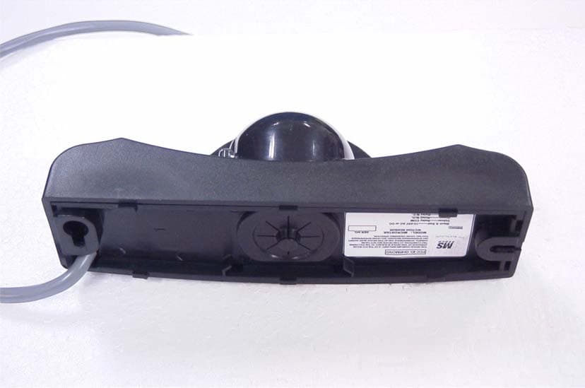
OHRMICRO
Oct 29, 2006MOTION SENSOR
Equipment Class
FDS - Part 15 Field Disturbance Sensor
OHRCP-TXHH
Dec 10, 2003CP/TX DUAL FREQUENCY R/C TRANSMITTER
Equipment Class
DSC - Part 15 Security/Remote Control Transmitter