OHRVPRField Disturbance Sensor
MS Sedco, Inc.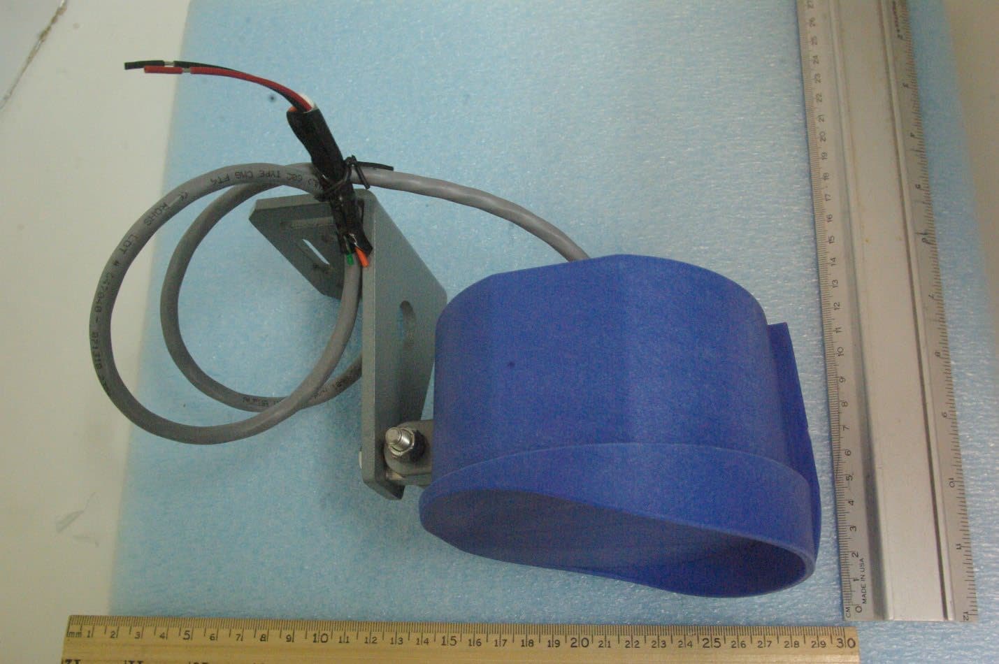
Click to zoom
Application Details
- Equipment Class
- FDS - Part 15 Field Disturbance Sensor
- Date of Grant
- Sep 24, 2023
- Application Purpose
- Original Equipment
- Date of Application
- Sep 24, 2023
- Equipment Note
- Field Disturbance Sensor
- Frequency Range
- 24075.00000000 - 24175.00000000
- Company
- MS Sedco, Inc.
- Country
- United States
Documents & Files
Document Text
Text extracted from the exhibit documents filed with the FCC. Open a document above to read the original.
Users Manual
DATASHEET OperatingFrequency24 GHz +/- 25MHz DetectionMethodDoppler Microwave Detection With Continuous Motion Range/Detection350feet(106meters)/ Approach, Depart, Bi-direction Angle (Adjustable,Tilt &Swivel) Horizontal: 18° Vertical: 9° ResponseTime0.2 Seconds With Adjustable Time Delay (0.2-8.0 seconds) Power Requirements/ CurrentConsumption 12V to24V AC orDC and solar power/ 75 mA (0.075 Amps) Relay OutputNC/NO/COM Temperature-35°F to165°F (-37°C to 75°C) Weight/Size1.55lbs.(0.7kg)/ 7.5"x6"x 5.5" (19cm x 15.2cm x 14cm) ColorRoyal Blue VPR-26 VEHICLE MOTION SENSOR Contact: 7898 Zionsville RD Indianapolis, IN 46268 Phone: (317) 842-2545 Email:[email protected]/[email protected] Website: www.mssedco.com
Users Manual
VPR-26 Vehicle Sensor Microwave Vehicle Motion Sensor INSTALLATION INSTRUCTIONS 7898 Zionsville Road Indianapolis, Indiana 46268 Telephone: (317) 842-2545 www.mssedco.com [email protected] Page 1 (82A043) VPR-26 v0917 Section 1 General Description The Model VPR-26 is a microprocessor-controlled vehicle sensor with a variable range. It is designed to trigger the operation of a traffic controller. The VPR-26 will only respond to motion in bi-direction or one direction (approach or depart only selectable), which makes it ideal for long-range detection at intersections. A micro- WARNING: To limit exposure to electrical damage from power surges, ALWAYS wire the sensor through the transformer that is provided or a TCPS series isolation module (sold separately). Wiring of the 5- conductor cable is as follows: processor analyzes the reflected microwave energy and responds to motion in the proper direction. The VPR-26 generates an extremely low power microwave beam aimed to cover the same area normally covered by a loop detector system. It is less expensive to install and less susceptible to damage and malfunction from ice, salt and heavy vehicular traffic. The VPR-26 operates on much the same principle that police radar uses. The unit transmits a low power micro- To VPR-26 Red = Power (un-fused) Black = Power Green = Relay COM Brown/Orange= Relay N. C. White = Relay N. O. 12V to 24V AC/DC (No Polarity) wave signal, some of which is reflected by a moving target, such as an automobile or truck. Larger vehicles, such as semi-trucks, reflect more energy than auto- mobiles and can be detected at further distances. Since the VPR-26 uses microwave signals as its means of detecting a moving target, it is not affected by air motion, temperature and humidity changes, or high frequency sounds. Section 2 Installation The VPR-26 vehicle sensor will perform best when it is aimed directly at traffic. This can be accomplished by mounting the unit at the typical mounting height of 10' to 22' and aiming the sensing head so it can "view" the traffic coming toward or moving away from the unit. Twist counter-clockwise and pull to open waterproof housing. Fuse = 0.5a; 250V; Fast Blo; 3AG Note: (Fuse Sold Separately) WARNING: Do Not ground one side of the secondary of the supply transformer. The VPR-26 is mounted with 2 lag bolts through 2 - 1/2" pre-punched mounting holes, or by banding to the poles. To remove the fastening bracket from the sensor, take out the 5/16-18 horizontal bolt holding the bracket to the hinge. Using the bracket as a template for locating screw holes, mark and drill the pole or band the bracket and refasten the sensor to the bracket with the 5/16-18 bolt The circuit ground of the unit is electrically connected to the housing. Grounding one side of the transformer may create a direct short that will blow the fuse located in the wire harness (pictured above). removed earlier. Wiring-(see wiring diagrams below) Operating voltage is 12V to 24V AC or DC and is usually supplied through a transformer. The current consumption of the unit is 0.075 Amps. NO AMPLIFIER REQUIRED! NOTE : 24V, 24VA transformer Sold Separately For more information, call us at (317) 842-2545. ! ! CONTACTS SHOWN WITH POWER APPLIED TO UNIT (FAILSAFE) ! VPR-26 Vehicle Sensor Microwave Vehicle Motion Sensor INSTALLATION INSTRUCTIONS 7898 Zionsville Road Indianapolis, Indiana 46268 Telephone: (317) 842-2545 www.mssedco.com [email protected] Page 2 (82A043) VPR-26 v0917 CAUTION: Do Not apply 120V AC primary power to the transformer until all secondary wiring is complete. Alignment To adjust the sensor's head angle, loosen the 5/16-18 hinge bolt. This allows vertical movement of the VPR-26. When alignment is complete, make sure that all bolts and screws are tightened. Adjustment All adjustments are made via the external controls located on the back panel of the unit (See Figure 1). Range Control- Allows the detection pattern to be varied to sense cars at a maximum of 300' and 380' for semi-trucks and larger vehicles. Delay Control- Allows adjustment of the relay hold time from 0.25-8.0 seconds. Direction Switch- Allows selectable sensor detection of traffic traveling in uni-direction or bi-direction from the sensor. Approach/Depart Switch- Allows selectable sensor detection of traffic traveling either towards/away from the sensor on bi-direction mode. An LED is located at both the front and back of the unit to provide visual confirmation that the unit is detecting traffic. Note: Click the Reset Button each time you make changes on the Dip Switches and Pods. Operation REMINDER: When power is applied, allow 30 Seconds warm-up before testing sensor. NOTE: This equipment has been tested and found to comply with the limits for a Class A digital device, pursuant to Part 15 of the FCC Rules. These limits are designed to provide reasonable protection against harmful interference when the equipment is operated in a commercial environment. This equipment generates, uses, and can radiate radio frequency energy and, if not installed and used in accordance with the instruction manual, may cause harmful interference to radio communications. Operation of this equipment in a residential area is likely to cause harmful interference. Note: The manufacturer is not responsible for any radio or TV interference caused by unauthorized modifications to this equipment. Such modifications could void the user's authority to operate the equipment. Section 3 Technical Data Model. .............................. VPR-26 Operating Frequency ....... 24 GHz +/- 25 MHz Detection Method. ........... Microprocessor-Analyzed Doppler Microwave Detection Pattern. ........... Adjustable (see Fig. 2) Detection Angle. ............... Adjustable, Tilt & Swivel Detection Mode. .............. Continuous with Motion Response Time. ............... 0.2 seconds Time Delay........................ Adjustable 0.2-8 .0 seconds Power Requirements. ...... 12V to 24V AC or D…
Text truncated - open the document above for the full version.
Cover Letter(s)
September 18, 2023 Timco Engineering Inc. 849 NW State Road 45 Newberry, FL 32669 Applicant: MS Sedco, Inc. 7898 Zionsville Road Indianapolis, IN 46268 CORES number: 0005088588 Equipment: FCC ID: OHRVPR FCC Rules: Parts 2, 15C To Whom It May Concern: The form 731 and application have been electronically submitted and any attachments will be uploaded to your web site for use in obtaining a grant of certification. Confidentiality is requested as outlined below. Permanent MS Sedco, Inc. requests that the material in the Block Diagram, Operational Description, and Schematics be withheld from public disclosure pursuant to Sections 0.457 and 0.459 of the Commission’s Rules following grant of the application. A statement of confidentiality will be attached with the application at the time of submittal. CONFIDENTIAL FILES VPR Conf BlkDia.pdf VPR Conf BlkDia1.pdf VPR Conf OpDes.pdf VPR Conf Schem.pdf Should you require any further information, please contact the undersigned. Thank you for your consideration in this matter. Sincerely, Scot Rogers Rogers Labs, Inc. Enclosures ROGERS LABS, INC. 4405 West 259 th Terrace Louisburg, KS 66053 Phone / Fax (913) 837-3214
Cover Letter(s)
Page 1 of 2 September 18, 2023 Timco Engineering Inc. 849 NW State Road 45 Newberry, FL 32669 Applicant: MS Sedco, Inc. 7898 Zionsville Road Indianapolis, IN 46268 Re: Confidentiality for submittal information regarding FCC ID: OHRVPR Product: Transmitter operated under 47CFR Section 15C Dear Sirs: MS Sedco, Inc. requests that the material in the Block Diagram, Operational Description, and Schematics be withheld from public disclosure pursuant to Sections 0.457 and 0.459 of the Commission’s Rules following grant of the application. In support of this request, MS Sedco, Inc. submits the following information. CONFIDENTIAL FILES VPR Conf BlkDia.pdf VPR Conf BlkDia1.pdf VPR Conf OpDes.pdf VPR Conf Schem.pdf 1. Identification of the specific information for which confidential treatment is sought: The materials set forth in the Block Diagram, Operational Description, and Schematics which are segregated, from the non-confidential exhibits of the application, are those for which confidentiality is sought. 2. Identification of the Commission proceeding in which the information was submitted or a description of the circumstances giving rise to the submission: The proceeding is that involving the application for equipment authorization (certification) under FCC ID: OHRVPR 3. Explanation of the degree to which the information is commercial or financial, or contains a trade secret or is privileged: This material includes a detailed Block Diagram, Operational Description, and Schematics. As such, this material is treated as highly confidential business information. ROGERS LABS, INC. 4405 West 259 th Terrace Louisburg, KS 66053 913 837-3214 Page 2 of 2 4. Explanation of the degree to which the information concerns a service that is subject to competition: The material for which confidentiality is sought is employed in the design and manufacture of this transmitting equipment that is offered on a highly competitive basis. Customers for this equipment have a variety of competing sources. 5. Explanation of how disclosure of the information could result in substantial competitive harm: Disclosure would, in effect, give away the fruits of the labors of MS Sedco, Inc.’s engineering personnel, who have designed the equipment and the manufacturing process. Disclosure would also offer competitors additional unwarranted insight into the state of the product development, thereby allowing competitors an advantage, not available to MS Sedco, Inc. 6. Identification of any measures taken by the submitting party to prevent unauthorized disclosure: The information for which confidential treatment is sought is kept confidential by MS Sedco, Inc. and not made available to third parties except pursuant to non-disclosure agreements. 7. Identification of whether the information is available to the public and the extent of any previous disclosure of the information to third parties: To the knowledge of those preparing this application, the information has not been disclosed publicly heretofore. While the general theory of operation of this equipment has been the subject of numerous disclosures in industry the protection sought is narrowly drawn as provided in regulations. 8. Justification of the period during which the submitting party asserts that the material should not be available for public disclosure: This material should not be disclosed for at least 25 years. While improvements in design are made relatively frequently, disclosure of the design information would lead to insights into both design and manufacturing techniques that could have an adverse competitive effect for many years to come. As such, it is important that the design not be made available to unauthorized persons who might attempt to use knowledge of the design to compromise the applications for which the equipment will be employed. Should you require any further information, please contact the undersigned. Thank you for your consideration in this matter. Sincerely, Scot Rogers
External Photos
Rogers Labs, Inc. MS Sedco SN: 629003 4405 West 259 th Terrace Model/HVIN: VPR PMN: VaPR FCC ID: OHRVPR Louisburg, KS 66053 Test: 230720 IC: 6775A-VPR Phone/Fax: (913) 837-3214 Test to: 47CFR 15.249, RSS-210 Date: September 21, 2023 Revision 1 File: VPR ExtPho Page 1 of 3 External photographs of equipment under test Rogers Labs, Inc. MS Sedco SN: 629003 4405 West 259 th Terrace Model/HVIN: VPR PMN: VaPR FCC ID: OHRVPR Louisburg, KS 66053 Test: 230720 IC: 6775A-VPR Phone/Fax: (913) 837-3214 Test to: 47CFR 15.249, RSS-210 Date: September 21, 2023 Revision 1 File: VPR ExtPho Page 2 of 3 Rogers Labs, Inc. MS Sedco SN: 629003 4405 West 259 th Terrace Model/HVIN: VPR PMN: VaPR FCC ID: OHRVPR Louisburg, KS 66053 Test: 230720 IC: 6775A-VPR Phone/Fax: (913) 837-3214 Test to: 47CFR 15.249, RSS-210 Date: September 21, 2023 Revision 1 File: VPR ExtPho Page 3 of 3
ID Label/Location Info
Rogers Labs, Inc. MS Sedco SN: 629003 4405 West 259 th Terrace Model/HVIN: VPR PMN: VaPR FCC ID: OHRVPR Louisburg, KS 66053 Test: 230720 IC: 6775A-VPR Phone/Fax: (913) 837-3214 Test to: 47CFR 15.249, RSS-210 Date: September 18, 2023 Revision 1 File: VPR LabelSmpl Page 1 of 1 Labe l Placement
Internal Photos
Rogers Labs, Inc. MS Sedco SN: 629003 4405 West 259 th Terrace Model/HVIN: VPR PMN: VaPR FCC ID: OHRVPR Louisburg, KS 66053 Test: 230720 IC: 6775A-VPR Phone/Fax: (913) 837-3214 Test to: 47CFR 15.249, RSS-210 Date: September 20, 2023 Revision 1 File: VPR IntPho1 Page 1 of 2 VPR-26 PCB IMAGE Front Panel Back Panel Rogers Labs, Inc. MS Sedco SN: 629003 4405 West 259 th Terrace Model/HVIN: VPR PMN: VaPR FCC ID: OHRVPR Louisburg, KS 66053 Test: 230720 IC: 6775A-VPR Phone/Fax: (913) 837-3214 Test to: 47CFR 15.249, RSS-210 Date: September 20, 2023 Revision 1 File: VPR IntPho1 Page 2 of 2 VaPR Sensor VPR-26/27 Image View
RF Exposure Info
Rogers Labs, Inc. MS Sedco SN: 629003 4405 West 259 th Terrace Model/HVIN: VPR PMN: VaPR FCC ID: OHRVPR Louisburg, KS 66053 Test: 230720 IC: 6775A-VPR Phone/Fax: (913) 837-3214 Test to: CFR47 15.245, RSS-210, RSS-Gen Date: September 18, 2023 Revision 1 File: VPR RFExp Page 1 of 1 M o d el: VPR Test Number:230720 MPE CalculatorRF Exposure uses EIRP for calculation. EIRP is based on TX power added to the antenna gain in dBi. dBi = dB gain compared to an isotropic radiator. S = p o we r d e ns ity in mW /c m^ 2 Transmitter Output power (mW)120.0 Transmitter Output power (W)0.12 Output Power for % duty Cycle operation (Watts)1000.12Antenna Gain (dBi)1 Output Power for 100% duty Cycle operation (Watts)0.12Antenna Gain (N umeric)1.26 Tx Frequency (MHz) 24125 Calculation power (Watts)0.12dBd + 2.17 = dBidBi to dBd2.17 Antenna Gain (dBd)-1.17 Cable Loss (dB)0.0Adjusted Power (dBm)20.79Antenna minus cable (dBi)1.00 Antenna Gain (N umeric)1.26 Calculated ERP (mw)91.660EIRP = Po(dBm) + Gain (dB) Calculated EIRP (mw)151.071Radiated (EIRP) dBm21.792 ERP = EIRP - 2.17 dB Radiated (ERP) dBm19.622 Occupational Limit 5 mW/cm 2 Frequency (MHz) O c c up a tio na l Limit (mW /c m 2 )P ub lic Limit (mW /c m 2 ) 50.0 W/m 2 30-30010.2 Ge ne ral Public Limit300-1,500f/300f/1500 1 mW/cm 2 1,500-100,00051 10.0 W/m 2 Occupational Limit 50 W/m 2 50 W/m 2 Frequency (MHz) O c c up a tio na l Limit (W /m 2 )P ub lic Limit (W /m 2 ) Ge ne ral Public Limit100-6,000 0.6455ƒ 0.5 10 W/m 2 6,000-15,00050 10 W/m 2 48-3001.291 300-6,000 0.02619ƒ 0.6834 6,000-15,0005010 15,000-150,0005010 Ge ne ra l P ub licOccupational f = Trans mit Frequency (MHz) f (MHz) =2412524125MHz P T = Power Input to Antenna (mW) P T (mW) = 120.0000120.0000 mW Duty cycle (percentage of operation) % =100100% P A = Adjusted Power due to Duty cycle or Cable Loss (mW) P A (mW) = 120.00120.00 mW G N = Numeric Gain of the Antenna GN (numeric) =1.261.26nume ric S 20 = Power Density of device at 20cm (mW/m 2 ) S 20 =(P A G N )/(4πR 20 ) 2 S 20 (mW /m 2 ) = 0.030.03 mW /m 2 S 20 = Power Density of device at 20cm (W/m 2 ) S 20 =(P A G N )/(4πR 20 ) 2 S 20 (W/m 2 ) = 0.300.30 W/m 2 S L = Po wer Den s it y Limit (W / m 2 ) FCC S L (W/m 2 )= 10.00050.000 W/m 2 S L = Po wer Den s it y Limit (W / m 2 ) Canada S L (W/m 2 )= 10.00050.000 W/m 2 R C = Minimum distance to the Radiating Element for Compliance (cm) FCC R C =√(P A G N /4πS L )R C (cm) =3.51.6cm R C = Minimum distance to the Radiating Element for Compliance (cm) Canada R C =√(P A G N /4πS L )R C (cm) =3.51.6cm S C = Power Density of the device at the Compliance Distance R C (W /m 2 ) FCC S C =(P A G N )/(4πR C ) 2 S C (W/m 2 ) = 10.0050.00 W/m 2 S C = Power Density of the device at the Compliance Distance R C (W /m 2 ) Canada S C =(P A G N )/(4πR C ) 2 S C (W/m 2 ) = 10.0050.00 W/m 2 R 20 = 20cm R20=2020cm For Compliance with Canada General Population Limits, User Manual must indicate a minimum separation distance of 3.5cm Or in Meters for Compliance with Canada General Population Limits, a minimum separation distance of 0.03Meters S umma ry: S ta nd a lo ne M P E C a lc ula tio ns a nd S umma ryP ub lic LimitP ub lic Tx Duty C ycle (%)Tx Frequency (MHz)Power Total (mW)Antenna Gain (numeric) S L (W/m 2 )S 20 (W/m 2 ) R C (c m) S C (W/m 2 ) FCC100241251201.2610.0000.303.510.00 Canada100241251201.2610.0000.303.510.00 O ve ra ll M inimum (c m)O ve ra ll M inimum (inc he s ) P ub licOccupational FCC (cm)3.51.6 FC C (inches)2.01.0 Canada (cm)3.51.6 Canada (inches)2.01.0 4 cm2 cm 2 inches1 inches FCC radio frequency radiation exposure limits per 1.1310 IC radio frequency radiation exposure limits per RSS-102 Limit O ve ra ll M inimum Limit P ub licO ve ra ll M inumu Limit O c c up p a tio na l EIRP Power density (S) mW/cm 2 =------- 4 pr^2 r (cm) EIRP (mW)
Test Report
9/13/2023CONFIDENTIAL1 VPR-26 Vehicle Detection Sensor VPR-26 Vehicle Detection Sensor 7898 ZIONSVILLE RDINDIANAPOLIS, IN 46268 9/13/2023CONFIDENTIAL2 Front Isometric View VPR-26 Vehicle Detection Sensor 7898 ZIONSVILLE RDINDIANAPOLIS, IN 46268 9/13/2023CONFIDENTIAL3 VPR-26 Vehicle Detection Sensor 7898 ZIONSVILLE RDINDIANAPOLIS, IN 46268 Right Side View 9/13/2023CONFIDENTIAL4 VPR-26 Vehicle Detection Sensor 7898 ZIONSVILLE RDINDIANAPOLIS, IN 46268 Rear Isometric View 9/13/2023CONFIDENTIAL5 VPR-26 Vehicle Detection Sensor 7898 ZIONSVILLE RDINDIANAPOLIS, IN 46268 Internal Component View 9/13/2023CONFIDENTIAL6 VPR-26 Vehicle Detection Sensor 7898 ZIONSVILLE RDINDIANAPOLIS, IN 46268 Exploded View
Test Report
NVLAP Lab Code 200087-0 Rogers Labs, Inc. MS Sedco SN: 629003 4405 West 259 th Terrace Model/HVIN: VPR PMN: VaPR FCC ID: OHRVPR Louisburg, KS 66053 Test: 230720 IC: 6775A-VPR Phone/Fax: (913) 837-3214 Test to: CFR47 15.245, RSS-210, RSS-Gen Date: September 18, 2023 Revision 1 File: MS Sedco VPR DXX TstRpt 230720 Page 1 of 30 47CFR, PART 15C - Intentional Radiators 47CFR Paragraph 15.245 and Industry Canada RSS-GEN Issue 5 and RSS-210 Issue 10 Application For Grant of Certification Model / HVIN: VPR 24.075-24.175 GHz Field disturbance sensors (FDS) FCC ID: OHRVPR IC: 6775A-VPR MS Sedco, Inc. 7898 Zionsville Road Indianapolis, IN 46268 FCC Designation: US5305 ISED Registration: 3041A Test Report Number: 230720 Test Date: July 20, 2023 Authorized Signatory: Scot D. Rogers This report shall not be reproduced except in full, without the written approval of the laboratory. This report must not be used by the client to claim product certification, approval, or endorsement by NVLAP, NIST, or any agency of the U.S. Government. ROGERS LABS, INC. 4405 West 259 th Terrace Louisburg, KS 66053 Phone / Fax (913) 837-3214 NVLAP Lab Code 200087-0 Rogers Labs, Inc. MS Sedco SN: 629003 4405 West 259 th Terrace Model/HVIN: VPR PMN: VaPR FCC ID: OHRVPR Louisburg, KS 66053 Test: 230720 IC: 6775A-VPR Phone/Fax: (913) 837-3214 Test to: CFR47 15.245, RSS-210, RSS-Gen Date: September 18, 2023 Revision 1 File: MS Sedco VPR DXX TstRpt 230720 Page 2 of 30 Table of Cont ents Table of Cont ents TABLE OF CONTENTS .................................................................................................. 2 REVISIONS ..................................................................................................................... 3 FOREWORD ................................................................................................................... 4 OPINION / INTERPRETATION OF RESULTS ............................................................... 4 EQUIPMENT TESTED .................................................................................................... 5 Equipment Function and Configuration ............................................................................................................ 5 Equipment Configuration.................................................................................................................................... 5 APPLICATION FOR CERTIFICATION ........................................................................... 6 APPLICABLE STANDARDS & TEST PROCEDURES .................................................. 7 TESTING PROCEDURES .............................................................................................. 7 AC Line Conducted Emission Test Procedure .................................................................................................. 7 Radiated Emission Test Procedure ..................................................................................................................... 7 Diagram 1 Test arrangement for Conducted Emissions ...................................................................................... 8 Diagram 2 Test arrangement for radiated emissions of tabletop equipment.................................................. 9 Diagram 3 Test arrangement for radiated emissions tested on Open Area Test Site .................................. 10 Test arrangement for radiated emissions Below 1 GHz .................................................................................... 10 Test arrangement for radiated emissions Above 1 GHz .................................................................................... 10 TEST SITE LOCATIONS .............................................................................................. 11 UNITS OF MEASUREMENTS ...................................................................................... 11 ENVIRONMENTAL CONDITIONS................................................................................ 12 STATEMENT OF MODIFICATIONS AND DEVIATIONS ............................................. 12 INTENTIONAL RADIATORS ........................................................................................ 12 Antenna Requirements ...................................................................................................................................... 12 Restricted Bands of Operation .......................................................................................................................... 12 NVLAP Lab Code 200087-0 Rogers Labs, Inc. MS Sedco SN: 629003 4405 West 259 th Terrace Model/HVIN: VPR PMN: VaPR FCC ID: OHRVPR Louisburg, KS 66053 Test: 230720 IC: 6775A-VPR Phone/Fax: (913) 837-3214 Test to: CFR47 15.245, RSS-210, RSS-Gen Date: September 18, 2023 Revision 1 File: MS Sedco VPR DXX TstRpt 230720 Page 3 of 30 Table 1 Radiated Emissions in Restricted Frequency Bands Data .................................................................... 13 Summary of Results for Radiated Emissions in Restricted Bands ................................................................ 13 AC Line Conducted EMI Procedure ................................................................................................................ 14 Figure 1 AC Line Conducted emissions Line L1 .............................................................................................. 15 Figure 2 AC Line Conducted emissions Line L2 .............................................................................................. 16 Table 2 AC Line Conducted Emissions Data L1 ............................................................................................... 17 Table 3 AC Line Conducted Emissions Data L2 ............................................................................................... 17 Summary of Results for AC Line Conducted Emissions Results ................................................................... 17 General Radiated Emissions Procedu…
Text truncated - open the document above for the full version.
Test Report
ε Ω
Test Setup Photos
Rogers Labs, Inc. MS Sedco SN: 629003 4405 West 259 th Terrace Model/HVIN: VPR PMN: VaPR FCC ID: OHRVPR Louisburg, KS 66053 Test: 230720 IC: 6775A-VPR Phone/Fax: (913) 837-3214 Test to: 47CFR 15.249, RSS-210 Date: September 18, 2023 Revision 1 File: VPR Short Term Conf TSup Page 1 of 4 Test setup photographs Rogers Labs, Inc. MS Sedco SN: 629003 4405 West 259 th Terrace Model/HVIN: VPR PMN: VaPR FCC ID: OHRVPR Louisburg, KS 66053 Test: 230720 IC: 6775A-VPR Phone/Fax: (913) 837-3214 Test to: 47CFR 15.249, RSS-210 Date: September 18, 2023 Revision 1 File: VPR Short Term Conf TSup Page 2 of 4 Rogers Labs, Inc. MS Sedco SN: 629003 4405 West 259 th Terrace Model/HVIN: VPR PMN: VaPR FCC ID: OHRVPR Louisburg, KS 66053 Test: 230720 IC: 6775A-VPR Phone/Fax: (913) 837-3214 Test to: 47CFR 15.249, RSS-210 Date: September 18, 2023 Revision 1 File: VPR Short Term Conf TSup Page 3 of 4 Rogers Labs, Inc. MS Sedco SN: 629003 4405 West 259 th Terrace Model/HVIN: VPR PMN: VaPR FCC ID: OHRVPR Louisburg, KS 66053 Test: 230720 IC: 6775A-VPR Phone/Fax: (913) 837-3214 Test to: 47CFR 15.249, RSS-210 Date: September 18, 2023 Revision 1 File: VPR Short Term Conf TSup Page 4 of 4
Contact Information
Applicant
Andrew Kaffenberger(Director of Procurement)
Test Firm
Rogers Labs, a division of The Compatibility CntrPatrick Powell
Technical Specifications
| # | Rule Parts | Frequency Range | Power Output |
|---|---|---|---|
| 1 | 15.245 | 24.07 GHz - 24.18 GHz | - |
Other Applications from MS Sedco, Inc.

OHRS-TRX
Apr 10, 2012SPECTRUM TRANSCEIVER
Equipment Class
DXX - Part 15 Low Power Communication Device Transmitter
OHRS-COR
Apr 01, 2012CLEARPATH SPECTRUM COORDINATOR
Equipment Class
DXX - Part 15 Low Power Communication Device Transmitter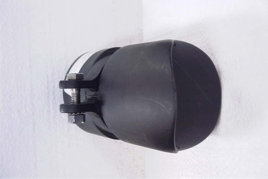
OHRWALK
Nov 06, 2006Pedestrian Sensor
Equipment Class
FDS - Part 15 Field Disturbance Sensor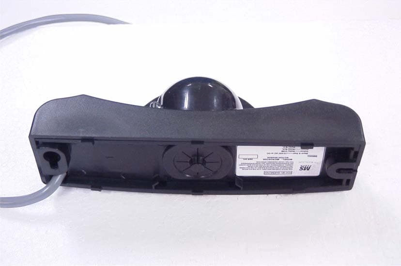
OHRMICRO
Oct 29, 2006MOTION SENSOR
Equipment Class
FDS - Part 15 Field Disturbance Sensor
OHRCP-TXHH
Dec 10, 2003CP/TX DUAL FREQUENCY R/C TRANSMITTER
Equipment Class
DSC - Part 15 Security/Remote Control Transmitter