OHRTC26Motion Sensor
MS Sedco, Inc.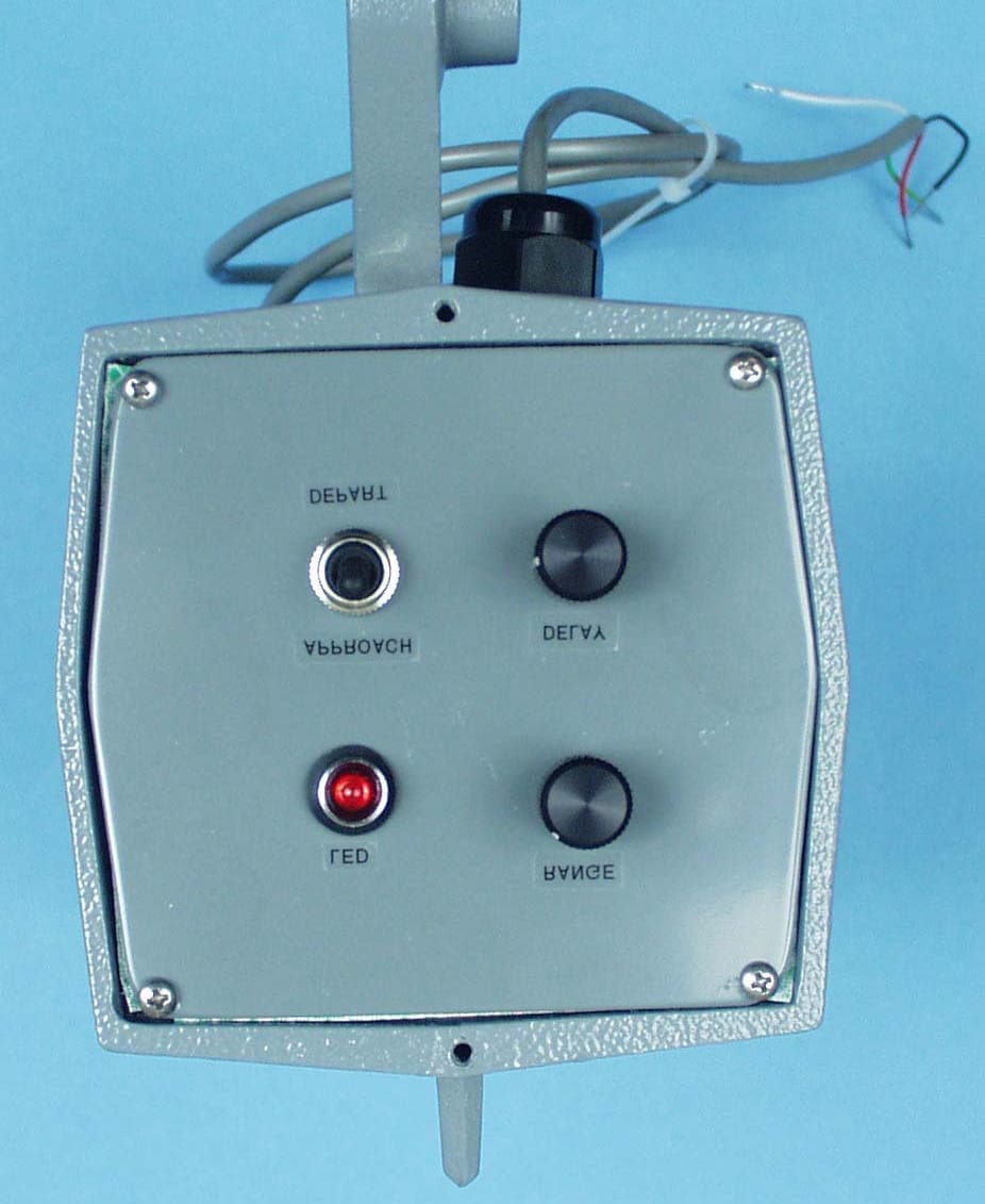
Click to zoom
Application Details
- Equipment Class
- FDS - Part 15 Field Disturbance Sensor
- Date of Grant
- Oct 16, 2001
- Application Purpose
- Original Equipment
- Date of Application
- Oct 16, 2001
- Equipment Note
- Motion Sensor
- Frequency Range
- 10524.00000000 - 10525.00000000
- Company
- MS Sedco, Inc.
- Country
- United States
Documents & Files
Document Text
Text extracted from the exhibit documents filed with the FCC. Open a document above to read the original.
Users Manual
- 1 - TC-26B Vehicle DetectorTC-26B Vehicle Detector INSTALLATION INSTRUCTIONS Section 1 General Description The Model TC-26B is a microprocessor controlled vehicle detector with a selectable range (long or short). It is designed to trigger the operation of a traffic controller. The TC-26B will only respond to motion in one direction (approach or depart only—selectable) which makes it ideal for long-range detection at intersections. A microprocessor analyzes the reflected microwave energy and responds to motion in the proper direction. The TC-26B generates an extremely low power microwave beam aimed to cover the same area normally covered by a loop detector system. It is less expensive to install and less susceptible to damage and malfunction from ice, salt and heavy vehicular traffic. The TC-26B operates on much the same principle that police radar uses. The unit transmits a low power microwave signal, some of which is reflected by a moving target, such as an automobile or truck. Larger vehicles, such as semi-trucks, reflect more energy than automobiles and can be detected at further distances. Since the TC-26B uses microwave signals as its means of detecting a moving target, it is not affected by air motion, temperature and humidity changes, or high frequency sounds. Section 2 Installation The TC-26B vehicle detector will perform best when it is aimed directly at traffic. This can be accomplished by mounting the unit at the typical mounting height of 14’ to 24’ and aiming the sensing head so it can “view” the traffic coming toward or moving away from the unit. Side-fire mounting is also acceptable. The TC-26B is mounted with 2 lag bolts through 2 - ½” prepunched mounting holes, or by banding to the poles. To remove the fastening bracket from the sensor, take out the ¼-20 bolt holding the bracket to the hinge. Using the bracket as a template for locating screw holes, mark and drill the pole or band the bracket and refasten the sensor to the bracket with the ¼-20 bolt removed earlier. Wiring - Operating voltage is 12V to 24V AC or DC and is usually supplied through a transformer. Current consumption of the unit is 0.075 Amps. NO AMPLIFIER REQUIRED! NOTE:18V, 20VA transformer included Wiring of the cable is as follows: Red & Black = 12V to 24 V AC/DC (no polarity) Brown = Relay COM Org = Relay N.O. Yel = Relay N.C. NOTE: Relay contact designation is with power applied. CAUTION: Do Not apply 120V AC primary power to the transformer until all secondary wiring is complete. NOTE:When power is applied, allow 30 Seconds of warm-up before testing sensor For more information, call us toll-free at (800) 842-2545. Alignment Align the TC-26B by adjusting the range control and the aiming angle. The range control allows the detection pattern to be varied to sense vehicles at a maximum of 200’ for cars, and 350’ for semi-trucks or other large vehicles. The Direction switch allows the sensor to detect traffic traveling either toward or away from the sensor. Please see Figure 1 for proper switch settings. To adjust the sensor’s head angle, loosen the ¼-20 hinge bolt. This allows vertical movement of the TC- 26B. When alignment is complete, make sure that all bolts and screws are tightened. Operation REMINDER: When power is applied, allow 30 Seconds warm-up before testing sensor. ! ! ! - 2 - NOTE: This equipment has been tested and found to comply with the limits for a Class A digital device, pursuant to Part 15 of the FCC Rules. These limits are designed to provide reasonable protection against harmful interference when the equipment is operated in a commercial environment. This equipment generates, uses, and can radiate radio frequency energy and, if not installed and used in accordance with the instruction manual, may cause harmful interference to radio communications. Operation of this equipment in a residential area is likely to cause harmful interference. Note: The manufacturer is not responsible for any radio or TV interference caused by unauthorized modifications to this equipment. Such modifications could void the user’s authority to operate the equipment. Section 3 Technical Data Model..............................TC-26B Operating Frequency.......10.525 GHz +/- 25 MHz Detection Method............Microprocessor-Analyzed Doppler Microwave Detection PatternAdjustable- (see Fig. 2) Detection Angle...............Adjustable, Tilt & Swivel Detection Mode...............Continuous with Motion Response Time...............0.150 seconds Time Delay......................Adjustable, 0-5 seconds Power Requirements.......12V to 24V AC or DC Wiring Requirements.......Four-Conductor Cable (see Wiring Section, Pg.1) Current Consumption.......75 mA (0.075 Amps) Power Consumption.........1.8 watts max. @ 24V Relay Contacts................Form C, rated at 3 amps Mounting.........................Heavy-duty bracket, predrilled & slotted for pole mount Temperature....................-35°F to 165°F (-37°C to 75°C) Weight.............................3 lbs. (1.4 kg) Size.................................7" x 4" x 4" (17.8cm x 10.2cm x 10.2cm) Color...............................Gray, Powder Coated Enclosure........................Aluminum with stainless steel hardware Section 4 Warranty MS Sedco guarantees this product to be free from manufacturing defects for one year from date of installation. Unless MS Sedco is notified of the date of installation, the warranty will be in effect for one year from the date of shipment from our factory. If, during the first year, this motion detector or support device fails to operate and has not been tampered with or abused, the unit can be returned prepaid to the factory and it will be repaired free of charge. After one year, the unit will be repaired for a nominal service charge. This limited warranty is in lieu of all other warranties, expressed or implied, including any implied warrantability of merchantability, and no representative or person is authorized to assume for MS Sedco any o…
Text truncated - open the document above for the full version.
External Photos
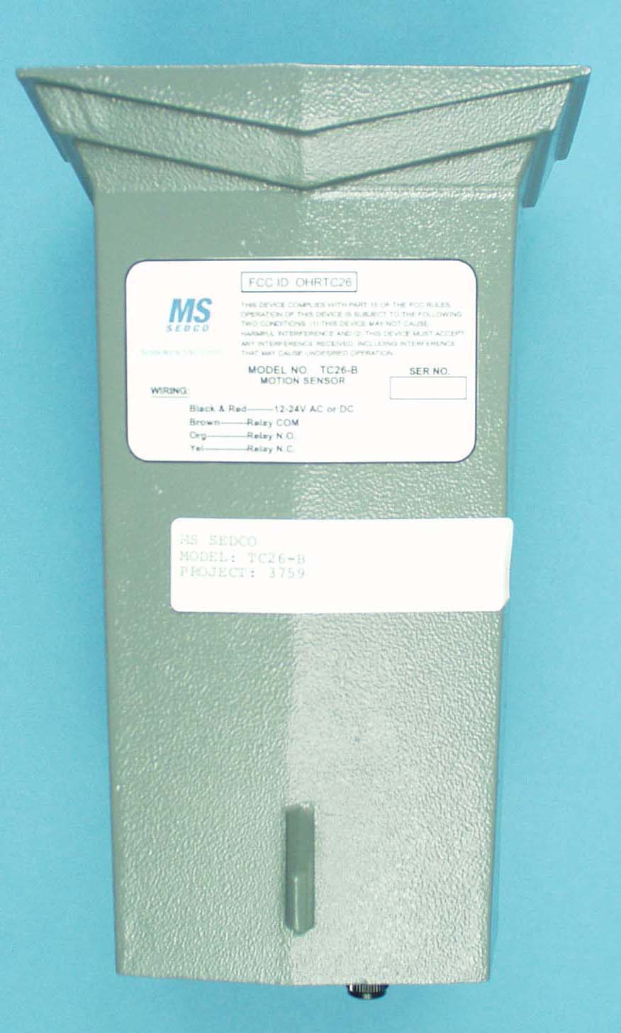
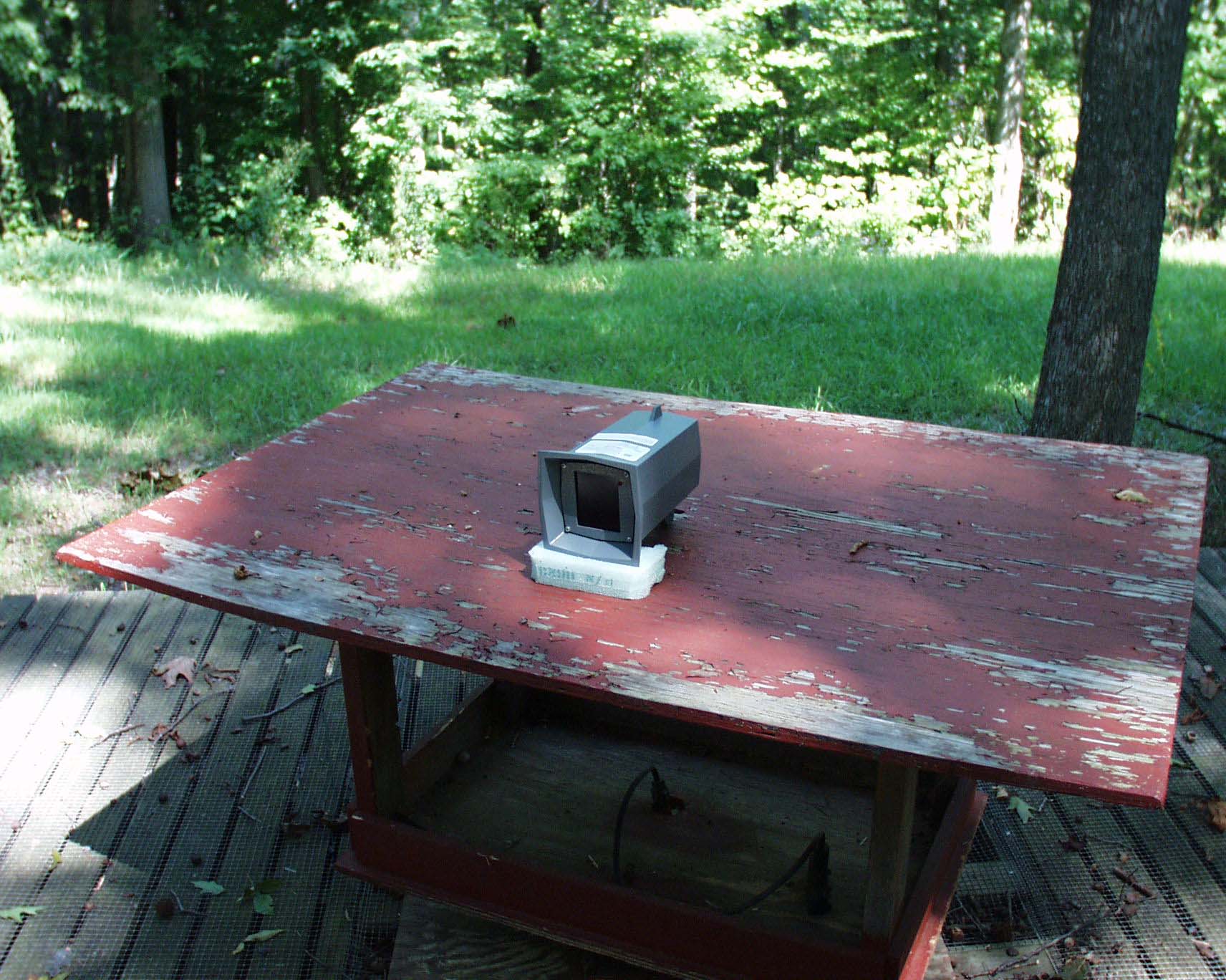
Top View Left Side View Bottom View Right Side View Back View Front View
Internal Photos
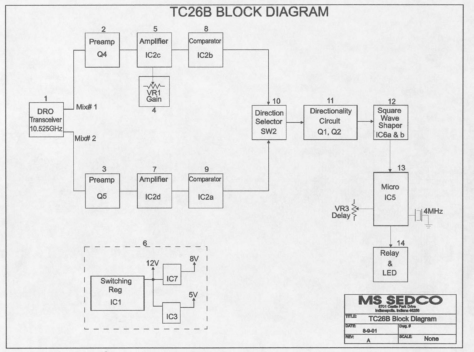
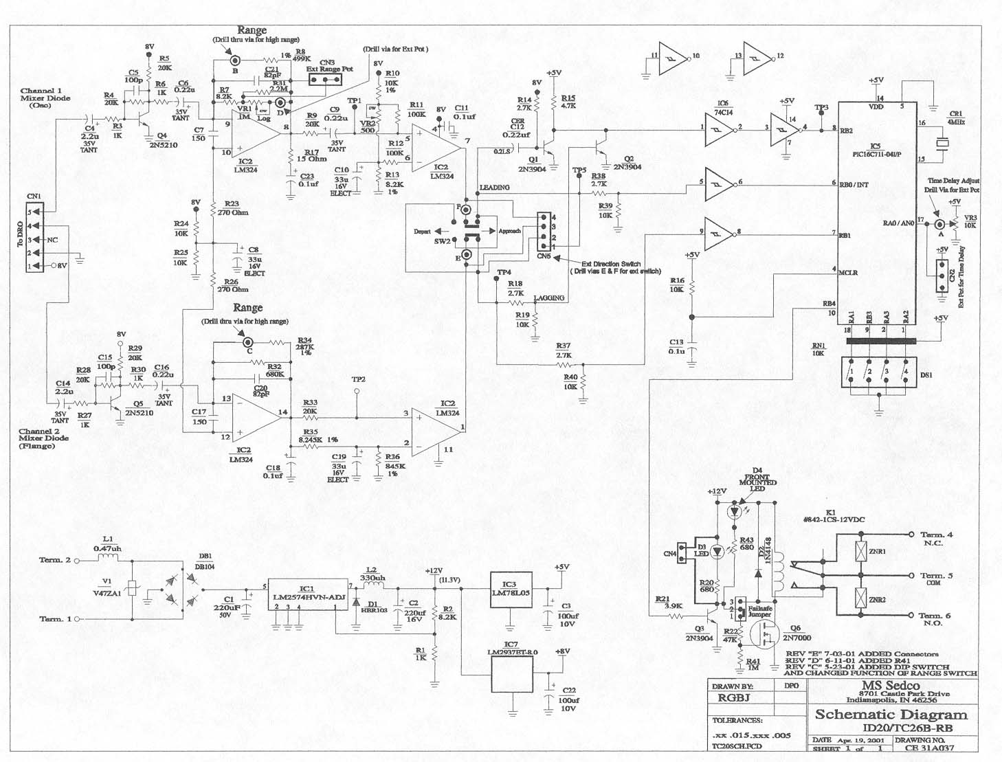
Internal Horn Internal Horn, Circuit Top Internal Horn Bottom Internal Circuit, Track Internal Top View Internal Circuit, Component Side Internal Rear Panel
Test Report
ENGINEERING STATEMENT For Certification of MS Sedco Model No: TC26-B FCC ID: OHRTC26 I am an Electronics Engineer, a principal in the firm of Hyak Laboratories, Inc., Springfield, Virginia. My education and experience are a matter of record with the Federal Communications Commission. Hyak Laboratories, Inc. has been authorized by MS Sedco to make measurements on the TC26-B field disturbance detector. These tests made by me or under my supervision in our Springfield laboratory. Test data and documentation required by the FCC are included in this report. ______________________________ Rowland S. Johnson Dated: October 5, 2001 A. INTRODUCTION The following data are submitted to establish compliance of the TC26-B transceiver in accordance with Part 2, Subpart J of the FCC Rules. The TC26-B detector is a microwave field disturbance sensor used as a vehicle detection unit, designed to be used as part of a traffic management system. The detector signals the presence of a vehicle by activating a relay. B. RESULTS SUMMARY The TC26-B detector met all the applicable requirements of Part 15.245, including the provisions of 15.245(1)(ii)) in the restricted bands of 15.209. C. DESCRIPTION OF RADIATED SPURIOUS MEASUREMENT FACILITIES A description of the Hyak Laboratories’ radiation test facility is a matter of record with the FCC. The facility was accepted for radiation measurements on October 1, 1976 and is currently listed as an accepted site. D. FIELD STRENGTH MEASUREMENTS OF SPURIOUS RADIATION The procedures of ANSI 63.4 (1992) were followed. Field intensity measurements of radiated spurious emissions from the TC26-B detector were made with a Tektronix 494P spectrum analyzer with external mixers using Polarad CA-L or CA-S or EMCO 3115 or EMCO 3116 horns. The transmitter was located in an open field 3 meters from the test antenna. Supply voltage was a terminal voltage under load of 18 Vdc. The transmitter and test antennae were arranged to maximize pickup. Both vertical and horizontal test antenna polarization were employed. Measurements were made from the lowest frequency generated within the unit (10.5 GHz), to the fifth harmonic (52.2 GHz) per FCC Rules 15.33(a)(2). Data after application of antenna factors and line loss corrections are shown in Table 1. 2 TABLE 1 RADIATED SPURIOUS EMISSIONS Measured at 3 meters PART 15(C) PARA. 15.245 Frequency Frequency To Which of Meter Antenna Field 1 Tuned Emission Reading Factor Intensity FCC Limit dB to __(GHz)__ __(GHz)_ _(dBm)_ __(dB)_ dBu @ 3m dBu @ 3m to Limit 10.5 10.526 -29.5 42.8 120.3 148 - 28 10.5 21.052 -74.3* 44.2 76.9 77.5 - 0.6 10.5 31.580 -77.5* 46.9 76.4 77.5 - 1.1 dBu = dBm + antenna factor + 107 * Measured @ 1 m, extrapolated to 3 m. All other spurious were below FCC limit or measurement system noise to the fifth harmonic. 3
Contact Information
Applicant
Andrew Kaffenberger(Director of Procurement)
Test Firm
Hyak Laboratories, Inc.Rowland Johnson
703-451-1188
Technical Specifications
| # | Rule Parts | Frequency Range | Power Output |
|---|---|---|---|
| 1 | 15.245 | 10.52 GHz - 10.53 GHz | - |
Other Applications from MS Sedco, Inc.
OHRVPR
Sep 24, 2023Field Disturbance Sensor
Equipment Class
FDS - Part 15 Field Disturbance Sensor
OHRS-TRX
Apr 10, 2012SPECTRUM TRANSCEIVER
Equipment Class
DXX - Part 15 Low Power Communication Device Transmitter
OHRS-COR
Apr 01, 2012CLEARPATH SPECTRUM COORDINATOR
Equipment Class
DXX - Part 15 Low Power Communication Device Transmitter
OHRWALK
Nov 06, 2006Pedestrian Sensor
Equipment Class
FDS - Part 15 Field Disturbance Sensor
OHRMICRO
Oct 29, 2006MOTION SENSOR
Equipment Class
FDS - Part 15 Field Disturbance Sensor