OJ7904FRS0401Family Radio Transceiver
Victory Concept Industries Ltd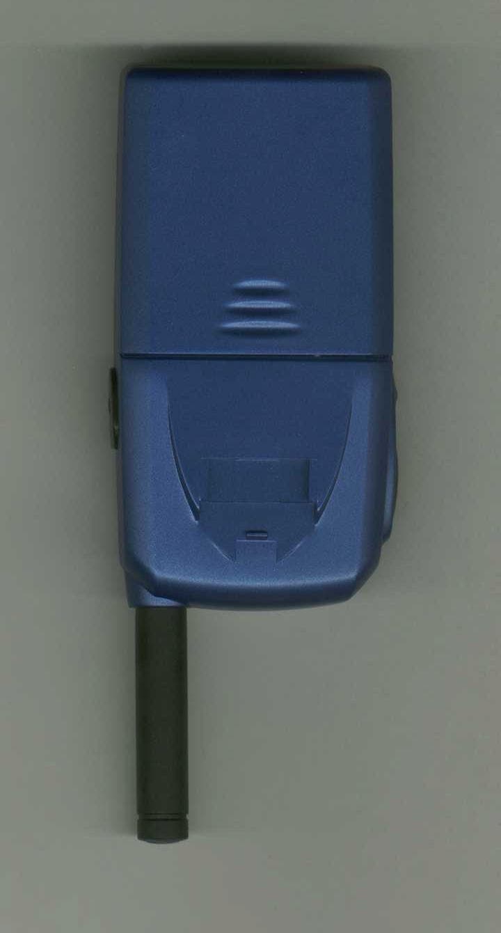
Click to zoom
Application Details
- Equipment Class
- FRF - Part 95 Family Radio Face Held Transmitter
- Date of Grant
- Jul 30, 2001
- Application Purpose
- Original Equipment
- Date of Application
- May 09, 2001
- Equipment Note
- Family Radio Transceiver
- Frequency Range
- 467.56250000 - 467.71250000
- Country
- Hong Kong
Documents & Files
Document Text
Text extracted from the exhibit documents filed with the FCC. Open a document above to read the original.
Users Manual
Victory Concept Ind. Ltd. FCC ID: OJ7904FRS0401 Job #: 363AH1 Exhibit #: 7A-7O Safety Information ! Your wireless handheld portable transceiver is a low power radio. When the PTT button is pushed it sends out radio frequency (RF) signals. In August 1996, the Federal Communications Commissions (FCC) adopted RF exposure guidelines with safety levels for hand-held wireless phones. Important: To maintain Compliance with the FCC’s RF exposure guidelines, if you wear a handset on your body use only the (brand name) supplied carrying case, holster or other body-worn accessory for this product and ensure that the antenna is at least 1 inch (2.5 centimeters) from your body when transmitting. Use only the supplied antenna. Unauthorized antennas, modifications, or attachments could damage the transmitter and may violate FCC regulations. Normal Position: Hold the transmitter approximately 1” from your face and speak in a normal voice, with the antenna pointed up and away.
ID Label/Location Info
MODEL: FRS125 FAMILY RADIO SERVICE (xx) DC 6V (1.5V X 4”AAA”/UM-3 BATTERIES) This device complies with Part 15 of the FCC rules. Operation is subject to the following two conditions:(1)this device may not cause harmful interference and(2)this device must accept any interference received,including interference that may cause undesired operation. Distributed by GPX, INC. FCC ID: OJ7904FRS0401 High Hill, MO 63350 USA Made in China Victory Concept Ind. Ltd. FCC ID: OJ7904FRS0401 Job #: 363AH1 Exhibit #: 1
ID Label/Location Info
Victory Concept Ind. Ltd. FCC ID: OJ7904FRS0401 Job #: 363AH1 Exhibit #: 2
Parts List/Tune Up Info
Tuning procedure Testing Condition 1. Speaker Load : 8 ohm 2. Modulation signal : 1000 Hz 3. Modulation deviation : 1.5 kHz 4. Antenna Load : 50 ohm 5. Channel : 4 6. Supply Voltage : 6.0VDC Channel Frequency Chart (FRS). Channel TX and RX Frequency (MHz) A 467.5625 B 467.6125 C 467.6625 D 467.7125 Test and Alignment procedure of main board 1. Align PLL Voltage 2. Align Tx frequency 3. Align 450KHz Quad Coil 4. Align RSSI 5. Align maximum modulation deviation 1. Align PLL Voltage 1.1 Terminate antenna to 50 ohm Loading. 1.2 Connect the voltage probe to the TP1 of RF board. 1.3 Press “PTT” Button to Tx mode 1.4 Align the spring coil (L6) to set a PLL voltage in Tx mode at 3.0V 1.5 Program the PLL to Rx mode and check PLL voltage is within 2.8V 2. Align Tx Frequency 2.1 Connect the RF probe to Antenna of the RF board 2.2 Press “PTT” Button to Tx mode 2.3 Align trimmer capacitor C79 so that frequency error is within +/- 400Hz 3. Align 450KHz Quad Coil 3.1 Connect the RF probe to Antenna of the RF board 3.2 Set RF Signal Gen. : Freq. dev. = 1.5KHz; Mod. Freq. : 1KHz; O/P Power = -50dBm 3.3 Set Volume Level 5 of the Dummy main board. 3.4 Align L1 for maximum o/p Level at “speaker +”. 4. Align RSSI 4.1 Continue the procedure of 3.3 4.2 Decrease the RF signal generator output level. Measure 12dB Sinad at speaker output. 4.3 Connect the voltage probe to TP10. 4.4 Set RSSI threshold by adjusting R129 so that “NO_RF” output starts to go from low level to high level. 5. Align Max. Modulation Deviation. 5.1 Align Sound Source sound pressure level is 110dBSPL 5.2 Press “PTT” Button to Tx mode, deviation limiting should be observed. 5.3 Align trimmer resistor (R81) to Max. modulation is 2.3-2.4kHz Dev. (15kHz LP Filter)
Test Report
TABLE OF CONTENTS LIST APPLICANT: VICTORY CONCEPT IND. LTD. FCC ID: OJ7904FRS0401 TEST REPORT: PAGE 1......COVER SHEET - GENERAL INFORMATION & TECHNICAL DESCR. PAGE 2......TECHNICAL DESCRIPTION CONTINUED & RF POWER OUTPUT PAGE 3......MODULATION CHARACTERISTICS AND OCCUPIED BANDWIDTH PAGE 4......METHOD OF MEASURING OCCUPIED BANDWIDTH PAGE 5......FIELD STRENGTH OF SPURIOUS EMISSIONS PAGE 6......METHOD OF MEASURING RADIATED SPURIOUS EMISSIONS PAGE 7......FREQUENCY STABILITY PAGE 8......LIST OF TEST EQUIPMENT EXHIBITS CONTAINING: EXHIBIT 1.........FCC ID LABEL SAMPLE EXHIBIT 2.........SKETCH OF FCC ID LABEL LOCATION EXHIBIT 3A........EXTERNAL PHOTO - FRONT VIEW EXHIBIT 3B........EXTERNAL PHOTO - REAR VIEW EXHIBIT 3C........INTERNAL PHOTO - SOLDER SIDE EXHIBIT 3D........INTERNAL PHOTO - COMPONENT SIDE EXHIBIT 4.........TEST SETUP PHOTOGRAPH EXHIBIT 5.........BLOCK DIAGRAM EXHIBIT 6A-6B.....SCHEMATIC EXHIBIT 7A-7O.....USER'S MANUAL EXHIBIT 8A-8B.....CIRCUIT DESCRIPTION EXHIBIT 9A-9B.....TUNING PROCEDURE EXHIBIT 10........AUDIO FREQUENCY RESPONSE GRAPH EXHIBIT 11A.......MODULATION LIMITING PLOT - 300 Hz EXHIBIT 11B.......MODULATION LIMITING PLOT - 1000 Hz EXHIBIT 11C.......MODULATION LIMITING PLOT - 3000 Hz EXHIBIT 12........AUDIO LOW PASS FILTER GRAPH EXHIBIT 13A.......OCCUPIED BANDWIDTH CW PLOT EXHIBIT 13B.......OCCUPIED BANDWIDTH PLOT APPLICANT: VICTORY CONCEPT IND. LTD. FCC ID: OJ7904FRS0401 REPORT #: T:\CUS\V\VICTORY\363AH1\363AH1RPT.doc PAGE: TABLE OF CONTENTS GENERAL_INFORMATION_REQUIRED FOR_TYPE_ACCEPTANCE 2.1033(c)(1)(2)VICTORY CONCEPT IND. LTD.will manufacture the FCCID: OJ7904FRS0401 FAMILY RADIO SERVICES 4 CHANNEL TRANSCEIVER in quantity, for use under FCC RULES PART 95. The UUT is a PTT Radio with a maximum duty cycle of 50%. VICTORY CONCEPT IND. LTD. RM. 1314-1315, KWONG SANG HONG CENTRE 151-153 HOI BUN ROAD, KWUN TONG KOWLOON HONG KONG 2.1033 (c) TECHNICAL_DESCRIPTION 2.1033(c)(3) Instruction book. A draft copy of the instruction manual is included as EXHIBIT 6A-6N. 2.1033(c) (4) Type of Emission: 10K6F3E 95.631 Bn = 2M + 2DK M = 3000 D = 2.0K Bn = 2(3.0)+2(2.3) = 10.6K Authorized Bandwidth 12.5KHz 2.1033(c)(5) Frequency Range: 1. 467.5625 95.627 2. 467.6125 3. 467.6625 4. 467.7125 MHz 2.1033(c)(6)(7) Power Output shall not exceed 0.500Watts effective 95.639 radiated power. There can be no provisions for 95.649 increasing the power or varing the power. The Maximum Output Power Rating: 400 milliWatts effective radiated power. 95.647 The antenna is an intergral part to the unit, it cannot be removed without rendering the unit inoperative. In order to remove the antenna the case must unscrewed, then the PCB assemblies must be removed then the antenna can be removed. 2.1033(c)(8) DC Voltages and Current into Final Amplifier: FINAL AMPLIFIER ONLY Vce = 6.0 Volts DC Ice = 0.144. Pin = .86 Watts APPLICANT: VICTORY CONCEPT IND. LTD. FCC ID: OJ7904FRS0401 REPORT #: T:\CUS\V\VICTORY\363AH1\363AH1RPT.doc PAGE #: 1 2.1033(c)(9) Tune-up procedure. The tune-up procedure is included as EXHIBIT 8A-8B. 2.1033(c)(10) Complete Circuit Diagrams: The circuit diagram is included as EXHIBIT 6A-6B of this report. The block diagram is included as EXHIBIT 5 of this report. 2.1033(c)(11) A photograph or a drawing of the equipment identifica tion label is included as exhibit No. 2. 2.1033(c)(12) Photographs(8"X10") of the equipment of sufficient clarity to reveal equipment construction and layout, including meters, labels for controls, including any view under shields - See EXHIBIT 3A-3D. 2.1033(c)(13) Digital modulation is not allowed. 2.1033(c)(14) The data required by 2.1046 through 2.1057 is submitted below. 2.1046(a) RF_power_output. 95.639 RF power is measured by measuring the radiated power at 3 meters and then replacing the transmitter with a signal generator to determine the effective radiated power. The ERP shall not exceed 0.500 Watts. MEASURED POWER OUTPUT = 400 milliWatts ERP R.F. POWER OUTPUT HP TEST SET UP Spectrum Analyzer /-------\ /-----------------\ | | | | TRANSMITTER | | | | | UNDER TEST WITH | \--| | | INTERNAL ANTENNA| | | | \-----------------/ | | | | | \-------/ | | |<-- 3.0 meters-->| /-------------\ | SIGNAL | DIPOLE | Tuned, Calibrated | GENERATOR | ANTENNA | Antenna which may | |----------/ be raised from 1 \-------------/ to 4 meters above ground and changed in polarization Equipment placed 80cm above ground on a rotatable platform. APPLICANT: VICTORY CONCEPT IND. LTD. FCC ID: OJ7904FRS0401 REPORT #: T:\CUS\V\VICTORY\363AH1\363AH1RPT.doc PAGE #: 2 2.1047(a)(b) Modulation_characteristics: AUDIO_FREQUENCY_RESPONSE The audio frequency response was measured in ac- cordance with TIA/EIA Specification 603. The audio frequency response curve is shown in exhibit 10 The audio signal was fed into a dummy microphone circuit and into the microphone connector. The input required to produce 30 percent modulation level was measured. 2.1047(b) Audio_input_versus_modulation The audio input level needed for a particular per- percentage of modulation was measured in accor- dance with TIA/EIA Specification 603. The audio input curves versus modulation are shown in exhibits 11A - 11C. Curves are provided for audio input frequen cies of 300, 1000, and 3000 Hz. 95.637(b) Post Limiter Filter The filter must be between the modulation limiter and the modulated stage. At any frequency between 3 & 20KHz the filter must have an attenuation of 60log (f/3) greater that the attenuation at 1KHz. See the plot; exhibit 12. 2.989(c) EMISSION BANDWIDTH: 95.633(c) Data in the plots shows that the sidebands from greater than 50% to 100% of the authorized bandwidth must be attenuated by at least 25dB and from 100 to 250% the sidebands must be attenuated by at least 35dB. Beyond 250% the sidebands must be attenuated by at least 43+log10(TP). The transmitter was modulated with 2500 Hz, adjusted for 50% modulation plus 16 dB. The spectrum analyzer was set with the unmodulated carrier at the top of the screen. The test p…
Text truncated - open the document above for the full version.
Test Report
Plot of audio post limiter filter -30 -25 -20 -15 -10 -5 0 5 100100010000 Frequency Level (dB) Level
Contact Information
Applicant
Samuel Cheng(R & D Manager)
Technical Contact
Timco Engineering, IncMario R de Aranzeta
[email protected]888-472-2424
849 NW State Road 45 · Newberry, Florida · United States
Non-Technical Contact
Timco Engineering, IncSharon A Hoffman
[email protected]888-472-2424
Test Firm
Timco Engineering, Inc.S Sanders
Technical Specifications
| # | Rule Parts | Frequency Range | Power Output | Emission | Tolerance |
|---|---|---|---|---|---|
| 1 | 95B | 467.5625 MHz - 467.7125 MHz | 400.00 mW | 10K6F3E | 0.0002500000 % |
Other Applications from Victory Concept Industries Ltd
OJ7DWST08810
May 09, 2023ToughSystem Music + Charger
Equipment Class
DXX - Part 15 Low Power Communication Device Transmitter
OJ7APS-JESS001
Nov 29, 2011AQ Smart Speaker with Apple AirPlay
Equipment Class
DTS - Digital Transmission System
OJ7901GMR0903
Nov 04, 2003FRS/GMRS UHF Transceiver
Equipment Class
FRF - Part 95 Family Radio Face Held Transmitter
OJ7CTAVC2101102
Jan 15, 20032.4GHz 40 Channel Analog Modulation Cordless Phone
Equipment Class
DXT - Part 15 Low Power Transceiver, Rx Verified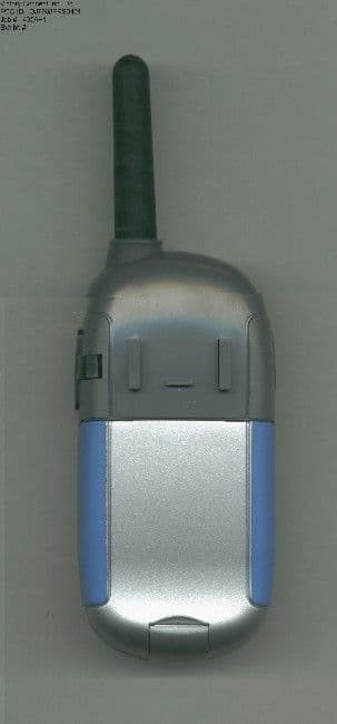
OJ7968FRS0401
Jan 03, 2002Family Radio Transceiver
Equipment Class
FRF - Part 95 Family Radio Face Held Transmitter