OK6X62410Printer Server
I-Data International A/S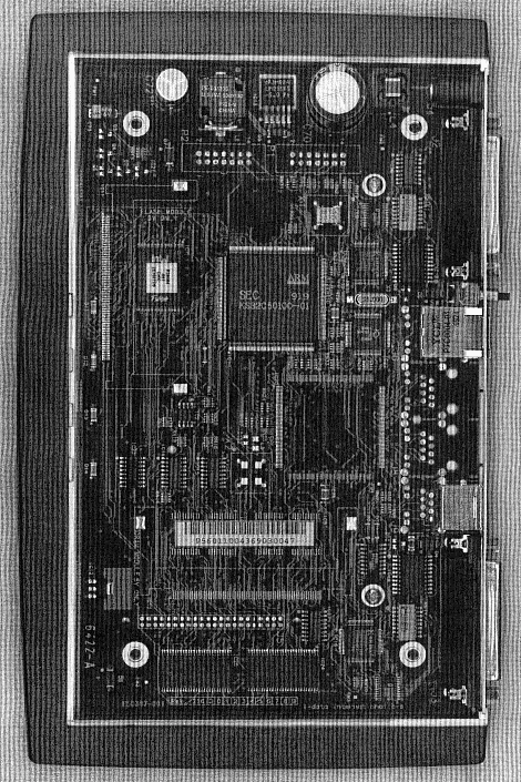
Click to zoom
Application Details
- Equipment Class
- JBP - Part 15 Class B Computing Device Peripheral
- Date of Grant
- Oct 25, 1999
- Application Purpose
- Original Equipment
- Date of Application
- Oct 03, 1999
- Equipment Note
- Printer Server
- Company
- I-Data International A/S
- Country
- Denmark
Documents & Files
Document Text
Text extracted from the exhibit documents filed with the FCC. Open a document above to read the original.
Users Manual
N OTE: T his equipment has been tested and found to comply with th e m its for a Class B digital device, pursuant to part 15 of the FCC R ules. These limits are designed to provide reasonabl e pr otection against harmful interference in a residential n stallation. T his equipment generates, uses and can radiate radio frequency en ergy and, if not installed and used in accordance with th e n structions, may cause harmful interference to radi o Co mmunications. However, there is no guarantee tha t n terference will not occur in a particular installation. If thi s eq uipment does cause harmful interference to radio or televisio n e ception, which can be determined by turning the equipmen t of f and on, the user is encouraged to try to correct th e n terference by one or more of the following measures: — Reorient or relocate the receiving antenna. — Increase the separation between the equipment and receiver. — Connect the equipment into an outlet on a circuit differen t r om that to which the receiver is connected. — Consult the dealer or an experienced radio/TV technician for he lp. C AUTION: C hanges or modifications not expressly approved by i-data could vo id the user’s authority to operate this equipment according t o pa rt 15 of the FCC rules. About i-dataFounded in 1981 and based in a suburb ofCopenhagen, Denmark, the i-data internationalgroup is comprised of two divisions. i-data PrintingSystems is the market and technology leader in theprinting connectivity market, and LASAT Networksis one of Europe’s leading vendors of Internetconnectivity products for small to medium-sizedenterprises. The combined company has aninstalled base of several million units. The i-datainternational group has approximately half theFortune 500 as customers, as well as thousands ofsmall to medium-sized enterprises worldwide. Thecompany's products are available in more than 40countries through an extensive network ofdistributors and sales offices.CE conformance This product has been developed and produced in accordance with the EMC directive and the Low Voltage directive and therefore carries the CE mark. Company and product names mentioned in this guide are trademarks or registered trademarks of their respective owners. 10411-01 PlusCom 10 / 100 X p re s ENGLISH ESPAÑO L E NGLISH = === T his Quick Guide explains how to install your P rintServer. I nstallation 1. Make sure no power cord is connected tothe PrintServer. 2. Connect network cable to the10/100BASE-TX port on the rear panel of the PrintServer. 3. The PrintServer is equipped with twoCentronics parallel ports: PAR1 and PAR2 , and an RS232 serial port: COM1. Connectthe printer to any of these. 4. Power on the printer. 5. Connect power supply, turning on thePrintServer. The green LEDs on thePrintServer front will blink during the poweron and self-test cycle. Only use the powersupply provided with the product. Theoutput is rated 12Vdc, 800 mA. 6. The complete Installation Guide will beprinted on the printer connected to PAR1 . G enerate Settin g s Printout 1. Make sure both PrintServer and printer ispowered on. 2. Generate a settings printout by pressingthe TEST key once on the PrintServer's rear panel. The test page(s) shows theinternal settings of the PrintServer. Thepage(s) are printed on the printerconnected to PAR1 . = ESPAÑOL = === Explica la manera de instalar el servidor de impresión. Instalación 1. Asegúrese de que el cable de alimentaciónno esté conectado al servidor de impresió n 2. Conecte el cable de la red al puerto10/100BASE-TX situado en el panel posterior del servidor de impresión. 3. El PrintServer está equipado con dospuertos paralelos Centronics: PAR1 y PAR2 , y un puerto serie RS232: COM1. Conecte la impresora a cualquiera de esto s puertos. 4. Encienda la impresora. 5. Conecte la alimentación eléctricaencendiendo el servidor de impresión. LosLEDs verdes situados en la parte delanter a del servidor de impresión parpadearándurante el ciclo de encendido yautocomprobación. 6. La Guía de instalación completa seimprimirá en la impresora conectada alpuerto PAR1 . Generar el impreso de losajustes 1. Asegúrese de que tanto el servidor deimpresión como la impresora esténencendidos. 2. Genere un impreso de los ajustes pulsand o una vez el botón TEST situado en el panel posterior del servidor de impresión. Lapágina o páginas de prueba mostrarán losajustes internos del servidor de impresión.Estas páginas se imprimirán en laimpresora conectada al puerto PAR1 .
Block Diagram
CPU 10MHz NETARM Samsung KC32C50100 (internal 50MHz) POW PS2 RS232 RAM FLASH Centronuíc Parallel OUT 1 and OUT 2 10/100 BASE Ethernet HUB 25MHz
Test Report
OK6X62410Page 1 OK6X62410Page 2 OK6X62410Page 3 OK6X62410Page 4 OK6X62410Page 5 OK6X62410Page 6 OK6X62410Page 7 OK6X62410Page 8
Contact Information
Applicant
Kim Boll Jensen(Manager, Approvals & Safety)
Test Firm
DELTA Electronic TestingJorgen Christensen
Technical Specifications
| # | Rule Parts | Frequency Range | Power Output |
|---|---|---|---|
| 1 | 15B | - | - |
Other Applications from I-Data International A/S
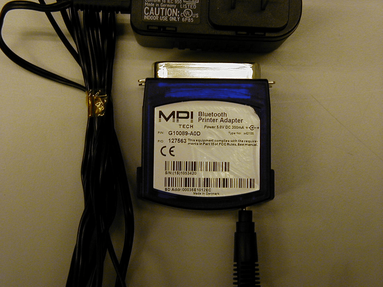
OK6X42100
Jun 25, 2001Bluetooth Printer Adapter
Equipment Class
DSS - Part 15 Spread Spectrum Transmitter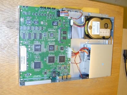
OK6X83106
Nov 21, 2000VPN router
Equipment Class
JBP - Part 15 Class B Computing Device Peripheral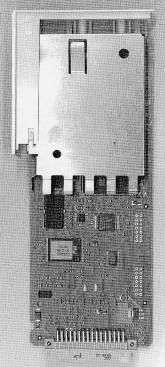
OK6X62512
Feb 14, 2000JBP - Part 15 Class B Computing Device Peripheral
Equipment Class
JBP - Part 15 Class B Computing Device Peripheral
OK6X34150
Nov 03, 1999Printer Server Terminal (SafeCom)
Equipment Class
JBP - Part 15 Class B Computing Device Peripheral
OK6X62411
Oct 17, 1999Printer Server
Equipment Class
JBP - Part 15 Class B Computing Device Peripheral