OOX-915ARadio Module
Vecima Networks Inc.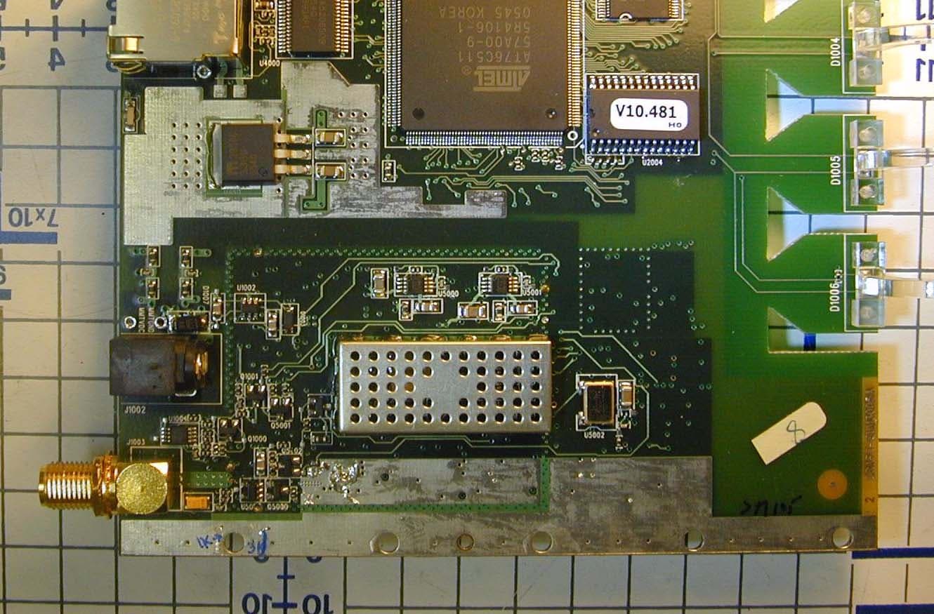
Click to zoom
Application Details
- Equipment Class
- DTS - Digital Transmission System
- Date of Grant
- Mar 27, 2006
- Application Purpose
- Original Equipment
- Date of Application
- Mar 27, 2006
- Equipment Note
- Radio Module
- Frequency Range
- 905.00000000 - 925.00000000
- Company
- Vecima Networks Inc.
- Country
- Canada
Documents & Files
Document Text
Text extracted from the exhibit documents filed with the FCC. Open a document above to read the original.
Users Manual
LMS3000 Technical Note Lawrence Gordon Page 1 of 8 Last saved on 27-Mar-06 5:45 PM F:\Tech Notes\TN131C - 915A Radio Operational Requirements.doc Number: TN131C Title: 915A Radio Operational Requirements Author: Lawrence Gordon Reviewer: Date: 27-Mar-06 Pages: 8 Abstract: This document lists the requirements that must be met in order to use the WaveRider 915A Radio in different packages and configurations. Revision History: Date Rev. Author Comments 24 Mar ‘06 A L. Gordon Initial Approval for AC to 4.2 VDC power supply; Indoor, and YAGI antennas 27 Mar ‘06 B L. Gordon Add FCC / IC Warnings, indicate that Radio Module can only to be installed by WaveRider manufacturers 27 Mar. ‘06 C L. Gordon Correct Antenna gain TN131C 915A Radio Operational Requirements Lawrence Gordon Page 2 of 8 Last saved on 27-Mar-06 5:45 PM F:\Tech Notes\TN131C - 915A Radio Operational Requirements.doc Table of Contents 1 Introduction........................................................................................................................ 3 1.1 References ................................................................................................................ 3 2 Requirements....................................................................................................................3 2.1 Regulatory Notices Requirements ............................................................................ 3 2.1.1 FCC.................................................................................................................... 4 2.1.2 Industry Canada ................................................................................................ 5 2.1.3 Installation Warnings ......................................................................................... 5 2.2 Final Product Installation Guide Requirements ........................................................ 5 2.3 Final Product Labeling Requirements....................................................................... 6 2.4 Power Supplies ......................................................................................................... 6 2.5 Antennas................................................................................................................... 7 2.6 External RF Connectors............................................................................................ 7 3 Approved Configurations .................................................................................................. 8 3.1 Approved Power Supplies......................................................................................... 8 3.2 Approved Antennas................................................................................................... 8 Table of Tables Table 1 – Approved Power Supplies........................................................................................ 8 Table 2 – Approved Antennas.................................................................................................. 8 TN131C 915A Radio Operational Requirements Lawrence Gordon Page 3 of 8 Last saved on 27-Mar-06 5:45 PM F:\Tech Notes\TN131C - 915A Radio Operational Requirements.doc Appendix A1 INTRODUCTION The WaveRider 915A Radio is certified by FCC and Industry Canada (IC) under a Limited Modular Approval (FCC ID: OOX-915A and IC ID: 3225B-915A). This means that the radio can be used in various packages and configurations provided the requirements below are met. These requirements apply to any WaveRider final product using the 915A radio. Note that this radio under the 915A certifications cannot be sold as a bare board to end- customers or OEMs. Only WaveRider manufactured final products can be sold. As such, this document is intended only for WaveRider or its contractors to act as an ‘installation guide’ for installing the 915A radio into a final product. Adhering to these requirements will not necessarily ensure compliance to FCC and IC requirements for the final product. If there are any concerns, testing should be done to ensure compliance. For example, the 915A radio meets the FCC and IC Class B unintentional radiator requirements as a standalone unit. If it is combined with other components or radios, the aggregate may not meet the same limits as the standalone unit. The term “final product” in this document will refer to the product that is sold that incorporates the 915A radio. WaveRider products that use the 915A radio currently includes the EUM2005. This document will be updated as new configurations are approved for the 915A radio, such as new antenna and power supplies. The approved configurations are shown in Section 3. WARNING – Final product (e.g. EUM3005, MMT9000, etc.) user documentation (e.g. Installation Guides, Spec. Sheets) must NOT contain any information about how the 915A radio is installed in the final product nor how to access the radio. A.1 1.1 References LMA PART 15 UNLICENSED MODULAR TRANSMITTER APPROVAL, DA 00-1407, June 26, 2000. Part 15 FCC CFR 47 Part 15 - RADIO FREQUENCY DEVICES, April 5, 2005. Appendix B2 REQUIREMENTS 2.1 Regulatory Notices Requirements Regulatory Notices This equipment has been tested and found to comply with the limits for a Class B Intentional Radiator, pursuant to Part 15 of the FCC Regulations. These limits are intended to provide pro- tection against harmful interference when the equipment is operated in a residential environment. This equipment generates, uses, and can radiate radio frequency energy and, if not installed and used in accordance with the instruction manual, may cause harmful interference to radio communications. However, there is no guarantee that interference will not occur in a particular installation. TN131C 915A Radio Operational Requirements Lawrence Gordon Page 4 of 8 Last saved on 27-Mar-06 5:45 PM F:\Tech Notes\TN131C - 915A Radio Operational Requirements.doc All versions of this device have been tested using unshielded Ethernet CAT-5 cable. Notice to U…
Text truncated - open the document above for the full version.
Block Diagram
WaveRider Communications (Canada) Inc. Suite 4, 6110 - 1A Street SW, Calgary, Alberta T2H 0G3 Tel/FAX: 403•253•5366 web: www.waverider.com 915A Block Diagrams The following are the block diagrams for the RF and digital sections of the 915A Circuit Card Assembly. The blocks shown are as follows: Top level RF section Ethernet PHY Microprocessor/MAC memory Microprocessor/MAC Baseband processor interface 1 Block Diagrams 1.1 Top Level Block Diagram Figure 1.1 – Top Level Block Diagram Page 2 Printed: 15-Mar-06 11:06 AM WaveRider Communications (Canada) Inc. Suite 4, 6110 - 1A Street SW, Calgary, Alberta T2H 0G3 Tel/FAX: 403•253•5366 web: www.waverider.com 1.2 RF Section Figure 1.2 – RF Section Block Diagram Page 3 Printed: 15-Mar-06 11:06 AM WaveRider Communications (Canada) Inc. Suite 4, 6110 - 1A Street SW, Calgary, Alberta T2H 0G3 Tel/FAX: 403•253•5366 web: www.waverider.com 1.3 Digital Section 1.3.1 Ethernet PHY ETHERNET PHY BLOCK ICS ICS1893AF TP_TXP TP_TXN MDIO MDC TP_CT RXD3 TP_RXP RXD2 TP_RXN RXD1 RXD0 RXDV RXCLK RXER REF IN REF OUT TXCLK 10TCSR TXEN TXD0 TXD1 TXD2 TXD3 COL 100TCSR CRS RESET_N P2LI P1CL P3TD P0AC P4RD RESET_ETH TXD0 2 IDATA- ODATA+ ODATA- IDATA+ MDIO RXD3 2 TPA TPB 25MHz 2 k Ω 1% 3.3V MDC RXD2 RXD0 RXD1 RX_DV RX _CLK RX _ER TX _CLK TX _EN TXD1 TXD2 TXD3 COL CRS 1.54 k Ω 1% Pull-downPull-down Pull-down Link LED Pull-up Pull-up 100pF Activity LED 5.3.1 Ethernet PHY Block Diagram Page 4 Printed: 15-Mar-06 11:06 AM WaveRider Communications (Canada) Inc. Suite 4, 6110 - 1A Street SW, Calgary, Alberta T2H 0G3 Tel/FAX: 403•253•5366 web: www.waverider.com 1.3.2 Microprocessor/MAC Memory (FLASH,SDRAM) 5.3.2 Microprocessor/MAC Memory Block Diagram Page 5 Printed: 15-Mar-06 11:06 AM WaveRider Communications (Canada) Inc. Suite 4, 6110 - 1A Street SW, Calgary, Alberta T2H 0G3 Tel/FAX: 403•253•5366 web: www.waverider.com 1.3.3 Microprocessor/MAC To RF 32 11 RX_DV MDI MDC RSSI LED 3.3V SEL[1] PAPE RADIO_PE RX_PE GPIO[5] TX_PE SYNTH_DATA SYNTH_CLK SEL[0] PAPE UART_RTS GPIO[4] GPIO[2] UART_CTS GPIO[3] GPIO[1] GPIO[0] 4 To Ethernet To Memory 2.5V RXD3 MDO RXD2 RXD1 RXD0 RX_CLK RX _ER TX_CLK TX _EN TXD0 TXD1 TXD2 TXD3 COL CRS RESET _ETH JTAGSerial 4 12 BBTXPE PE1 PE2 CAL _EN RFSW M _SD_IF_RF M_SCLK_IF_RF M_LE_RF M_LE_IF RX_CLK RX _DATA MD_RDY TX _CLK TX _DATA TX _RDY CCA BB _RX_PE BB _TX_PE /RESET BB _CLK BB _DATA R/nW /CS_BBP To BBP Buffer MDIO Reset 3.3V 22MHz MDIO 5.3.3 Microprocessor/MAC Interface Block Diagram Page 6 Printed: 15-Mar-06 11:06 AM WaveRider Communications (Canada) Inc. Suite 4, 6110 - 1A Street SW, Calgary, Alberta T2H 0G3 Tel/FAX: 403•253•5366 web: www.waverider.com 1.3.4 BBP Interface BBP BLOCK TO RF IFDET TXI+/- TXQ+/- VREF RXI+/- RXQ+/- TXIFAGC RFIFAGC 2 2 2 2 3.3V 11MHz HFA3861B RX_CLK RX_DATA MD_RDY TX_CLK TX_DATA TX_RDY CCA BB_RX_PE BB_TX_PE /RESET BB_DATA BB_CL K R/nW /CS_BBP To MICRO /MAC ÷4 44MHz ÷2 22MHz ANTSEL RXRFAGC 5.3.4 BBP Interface Block Diagram
Cover Letter(s)
WaveRider Communications (Canada) Inc. Suite 4, 6110 - 1A Street SW, Calgary, Alberta T2H 0G3 Tel/FAX: 403•253•5366 web: www.waverider.com 15 March 2006 Curtis-Straus LLC, 527 Great Road Littleton, MA, USA 01460 Reference: WaveRider 915A (FCC ID OOX-915A) Request for Confidentiality WaveRider Communications request that the following information regarding the submission of the 915A be withheld from public inspection, in accordance with CRF 0.457 and 0.459: • Circuit schematics (file: 915A_REV2_SCHEMATIC.pdf) • Bill of materials (file: 915A_REV2_BOM.xls) The reasons for which confidentiality has been requested are: • This product serves a unique and competitive niche in the wireless market. • This information is considered to be proprietary in nature. • This information is considered to be commercially and competitively sensitive. Lawrence Gordon, Senior Technical Design Lead, WaveRider Communications (Canada) Inc. Suite 4, 6110 - 1A St. SW, Calgary, Alta, T2H 0G3 Tel/FAX: (403) 253-5366, Tel: (403) 616-5668(cell)
Cover Letter(s)
Mr. Gordon, Please address the following issues for this application, 2. Please clarify if the antennas connected to the module were maximized for different polarizations within their range of motion. [LAG] The WaveRider Antenna has a vertical polarization. The diversity is based on switching beam patterns, with the primary beam pattern having the maximum gain along the normal vector to the antenna ground plane. The secondary beam pattern has its maximum peak at about 90 degress horizontal to the primary and is also vertically polarized, but the peak is about 3 dB less than the primary beam pattern. The WaveRider antenna was tested so that it directly faced the test antenna with no up or down tilt so that the test antenna would see the peak antenna gain. The variable elevation of the test antenna and rotation of the test table ensure that any alignment errors are found. [LAG] The YAGI antenna can be physically mounted for either horizontal or vertical polarization. The test lab chose the horizontal polarization so that the maximum gain would be seen on the horizontal orientation of the test antenna and the max. sidelobes of the YAGI beam patterns would be seen doing the test table rotation. Again, any alignment errors would be removed by the test table rotation and test antenna elevation changes. So the short answer is "yes the antennas were maximized for their polarization". [LAG] The following is a statement from our test lab in response to your question: ----------------------------------------- Hello, Lawrence; The EUT yagi antenna was mounted in horizontal polarization on the turntable. This was rotated through 360 degrees to determine the azimuth relative to the receiving antenna that produced the maximum emission at each test frequency. The receiving antenna was scanned from 1 m to 4m in order to find the height at which the received emission was maximum. These maximization searches were performed for both polarizations of the receiving antenna. Please contact me if you have any questions or comments. Regards, David Raynes [email protected] Laboratory Supervisor Electronics Test Centre (Airdrie) [LAG] ------------------------------------------------------------------------- ***********Follow up by TCB to item 2 *************** In your response to item 2, it appears YAGI antenna has been tested in H polarization only. If there will be installations where the installer will make use of the V polarization, the test data does not specifically represent this case. Please clarify how compliance is ensured in case of V polarity. For a YAGI, the E-plane is the plane in which the dipole elements lie and the H plane is the plane at right angles to the E-plane and along the main strut of the YAGI. For the antenna in the horizontal position, as in our test, the E-plane is scanned for a full 360 degrees since it is parallel to the turntable. The H-plane is scanned from -18 degrees (test antenna at 0 (1 meter below height of antenna) to about 45 degrees ( 3 meter elevation over 3 meter distance). This is direct line of sight. As you can see from the spec sheets, the 3 dB beamwidth of a 13 dBi YAGI is 35-40 degrees in the E-plane (i.e. +/- 17 to 20 degrees from the main antenna strut), and 40-45 degrees in the H- plane (i.e. +/- 20 to 23 degrees from the main antenna strut). And as the beam patterns show the biggest sidelobe for a 13 dBi YAGI is at least 12 dB less than the main lobe. From this, I conclude that inspection of the main lobe is representative of the worst case possible for a YAGI antenna and for a high-gain YAGI this main lobe is less than +/- 25 degrees off the main strut line, in both planes. So, the testing of the antenna over 360 degrees of the E-plane and -18 to +45 degrees of the H-plane more than covers the main lobe. Turning the antenna 90 degrees to vertical polarization would swap the E and H planes, but not affect the main lobe geometry. And the main lobe geometry is confirmed by the test report, where all peaks with the Horizontal test antenna are directly in front of the antenna (0, 4 and 360 degrees for 905, 915 and 925 MHz). The Vertical/Horizontal ratio is at least 20 dB as shown by the test report. All peaks (carrier and spurious emissions in restricted bands) were within 30 cm of the antenna height (1 m) or less than 6 degrees. When we tested the same antenna in the vertical position for the EUM3004, all peaks were found by the vertical orientation of the test antenna at 0 degrees azimuth and an antenna height of 100 cm, or 0 degrees with respect to the antenna. This shows the same main lobe geometry as the current testing, notwithstanding the 90 change in antenna orientation. Given these arguments and the previous testing of the identical antenna for our predecessor products in the other orientation with no adverse findings, I think it is safe to conclude that this testing of the YAGI is sufficient for either polarization. 3. Please provide specifications of unique antenna connector that is currently on the module. [LAG] See WBF (000-958) Data Sheet.pdf and WCM (000-957) Data Sheet.pdf for the board and cable connectors. These connectors were designed exclusively for WaveRider, which holds the exclusive rights to these connectors. 4. The test report shows a maximum conducted output power measurement of 27.9 dBm. Other exhibits of the application shows 27.3dBm. Please clarify or supply corrected exhibits (RF exposure, etc.) [LAG] The max. output power is set for each and every modem at the factory during production. We have been setting our current modems to 27.3 dBm and wish to continue to do so. However, during FCC testing, we set the unit to as high an output power as we can and still pass. In this case, the output power is between 27.6 and 27.9 dBm depending on frequency. By having test results showing that we pass at a higher output power than we will be producing gives us confidence that our units will remain FCC compliant. We also prefer the slightly …
Text truncated - open the document above for the full version.
Cover Letter(s)
WaveRider Communications (Canada) Inc. Suite 4, 6110 - 1A Street SW, Calgary, Alberta T2H 0G3 Tel/FAX: 403•253•5366 web: www.waverider.com 15 March 2006 Barry C. Quinlan, Certification Manager, Curtis-Straus LLC, 527 Great Road, Littleton, MA Dear Barry, RE: FCC Submission OOX-915A WaveRider is requesting that Curtis-Straus review and certify our 915A radio as a Digital Transmission System under FCC Part 15. We are applying for a Limited Modular Approval for this radio, since we expect to use this radio in several final products. These final products will all be manufactured by WaveRider only. In accordance with directive DA 00-1407 (June 26, 2000) “Part 15 Unlicensed Modular Transmitter Approval”, I have addressed each of the numbered requirements below: 1. “The modular transmitter must have its own RF shielding”. There are two shields on the radio, one covering the receiver and transmitter circuitry and one covering the local oscillator. Proof that these shields prevent coupling of the RF circuitry and any wiring is provided in the test report showing the results of testing the bare circuit card assembly without any housing. 2. “The modular transmitter must have buffered modulation/data inputs”. The radio accepts data from an Ethernet port only. The radio processors buffer this data and generate modulated signals internally to the radio. The user cannot over modulate or exceed the data rates set by the RF design. 3. “The modular transmitter must have its own power supply regulation”. The 915A uses an external AC to 4.2 VDC power supply to regulate all power coming from the AC lines before it gets to the Circuit Card Assembly. This power supply is included in all testing of this radio. It provides isolation between the radio and the AC lines. Beyond that, there are voltage regulators and power filters on-board the radio to reduce any conducted emissions to the 4.2 VDC line. 4. “The modular transmitter must comply with the antenna requirements of Section 15.203 and 15.204(c)”. This specific version of the 915A radio complies with this requirement, since it has a WaveRider proprietary unique RF connector. This is the same connector that is used on other WaveRider products (e.g. OOX-EUM3005). Other versions of the 915A radio and its final products may use other RF connectors requiring Professional Installations only. It is for this reason alone that we are applying for a Limited Modular Approval instead of a full modular approval. 5. “The modular transmitter must be tested in a stand-alone configuration”. The 915A is tested as a bare circuit card assembly (CCA). AC power is passed to the AC to 4.2 VDC power supply and hence to the CCA. The power supply is specified as a necessary accessory for this radio. All testing includes the power supply. 6. “The modular transmitter must be labeled with its own FCC ID number, and, if the FCC ID is not visible when the module is installed inside another device, then the outside of the device into which the module is installed must also display a label referring to the enclosed module”. See “FCC - 915A Product Label.pdf”, submitted as part of the documentation package, to see the format and location of both the label on the radio itself as well as label on the packaged radio. WaveRider Communications (Canada) Inc. Suite 4, 6110 - 1A Street SW, Calgary, Alberta T2H 0G3 Tel/FAX: 403•253•5366 web: www.waverider.com 7. “The modular transmitter must comply with any specific rule or operating requirements applicable to the transmitter and the manufacturer must provide adequate instructions along with the module to explain any such requirements”. See “FCC/IC – 915A Module Operating Requirements.pdf”, submitted as part of the documentation package, for specific requirements, such as antenna types acceptable, installation requirements, etc. 8. “The modular transmitter must comply with any applicable RF exposure requirements”. See “FCC/IC – 915A Module Operating Requirements.pdf”, submitted as part of the documentation package, for specific requirements, such as antenna types acceptable, required cable losses and separation requirements. WaveRider is applying for a Limited Module Approval for the 915A since future versions of this product will be completely under WaveRider’s control by being the manufacturer and integrator ourselves. Your Truly, Lawrence Gordon, Senior Technical Design Lead, WaveRider Communications (Canada) Inc. Suite 4, 6110 - 1A St. SW, Calgary, Alta, T2H 0G3 Tel/FAX: (403) 253-5366, Tel: (403) 616-5668(cell)
Cover Letter(s)
WaveRider Communications (Canada) Inc. Suite 4, 6110 - 1A Street SW, Calgary, Alberta T2H 0G3 Tel/FAX: 403•253•5366 web: www.waverider.com 15 March 2006 RE: WaveRider 915A (FCC ID OOX-915A) The manufacturer information of the 915A is as follows: Solectron EMS Canada, 425 Legget Drive, Kanata, Ontario, K2K 2W2 Lawrence Gordon, Senior Technical Design Lead, WaveRider Communications (Canada) Inc. Suite 4, 6110 - 1A St. SW, Calgary, Alta, T2H 0G3 Tel/FAX: (403) 253-5366, Tel: (403) 616-5668(cell)
Cover Letter(s)
CONNECTOR TECHNICAL DATA SHEET CONNECTOR SERIES:CONNECTOR SERIES:: FCC CABLE PLUG: FCC CABLE PLUG CENTER CONDUCTOR:: MALE PIN NOMINAL IMPEDANCE (OHMS): 50 SEPARATE CONTACT:: YES CABLE ACCOMIDATION: LMR-200 : : CONTACT CAPTIVATION:: N/A CABLE ATTACHMENT:: CRIMP CONTACT ATTACHMENT:: SOLDER FREQUENCY RANGE:: DC TO 2.5 GHZ QPL SPECIFICATION:: N/A QPL EQUIVALENT:: N/A ITEMMATERIALSFINISHES BODY : BRASS PER ASTM B16 : GOLD PLATE PER MIL-G-45204 NUT : BRASS PER ASTM B16 : GOLD PLATE PER MIL-G-45204 NUT RING : COPPER BERYLLIUM PER ASTM B196 OR B197 : NONE GASKET : SILICON RUBBER PER ZZ-R-765 : NONE INSULATOR : PTFE PER ASTM-D-1710 : NONE CONTACT : COPPER BERYLLIUM PER ASTM B196 : GOLD PLATE PER MIL-G-45204 MATING CHARACTERISTICS: 50 OHM PIN CONTACT PER TENSOLITE-STD-348-W310.1K MATING TORQUE: 7 TO 10 POUND INCHES MOUNTING TORQUE: N/A TEMPERATURE RANGE: -55 / +125 DEG C ELECTRICAL: VSWR MAXIMUM: 1.05 * F^.03 (F IN GHZ) INSERTION LOSS MAXIMUM: 0.015 * F^.5 (F IN GHZ) IMPEDANCE: 50 OHMS NOMINAL D.C. RESISTANCE: 5,000 MOHMS MINIMUM FEATURES * LOW VSWR THROUGH OPERATING FREQUENCY. * OVERSIZE .312-32 THREAD. * OVERSIZED BODY MATING DIAMETER. * NOTE: * NOT FOR PUBLIC RESALE. * UNIQUE FOR CUSTOMER 1002 ONLY. * CUSTOMER PART NUMBER 000-957 T:\datashet\technica\CONN\WAVR\STCP\MOD1PART NUMBER:WAVR-STCP-MOD1 DATA SHEET REVISION: 3/19/2001 COPYRIGHT 2000 / 2001 TENSOLITE CO. QMI IS A REGISTERED TRADEMARK OF TENSOLITE CO.DATA SUBJECT TO CHANGE CONNECTOR TECHNICAL DATA SHEET CONNECTOR SERIES:CONNECTOR SERIES:: FCC PCB RT.< JACK: FCC PCB RT.< JACK CENTER CONDUCTOR:: FEMALE SOCKET NOMINAL IMPEDANCE (OHMS): 50 SEPARATE CONTACT:: YES CABLE ACCOMMODATION: N/A CONTACT CAPTIVATION:: 6 POUNDS BOARD ATTACHMENT:: SOLDER CONTACT ATTACHMENT:: SOLDER FREQUENCY RANGE:: DC TO 6 GHz QPL SPECIFICATION:: N/A QPL EQUIVALENT:: N/A ITEMMATERIALSFINISHES HARDWARE : BRASS PER ASTM B16 : GOLD PLATE PER MIL-G-45204 BODY : BRASS PER ASTM B16 : GOLD PLATE PER MIL-G-45204 INSULATOR : PTFE PER ASTM-D-1710 : NONE CONTACT : COPPER BERYLLIUM PER ASTM B196 : GOLD PLATE PER MIL-G-45204 MATING CHARACTERISTICS: 50 OHM SOCKET CONTACT PER QMI-STD-348-W310.2 MATING TORQUE: 7 TO 10 POUND INCHES TEMPERATURE RANGE: -55 / +125 DEG C MOUNTING TORQUE: 15 TO 18 POUND INCHES ELECTRICAL: VSWR MAXIMUM: 1.05:1 +.07 * F^.07 (F IN GHz) INSERTION LOSS MAXIMUM: 0.020 * F^.5 (F IN GHz) IMPEDANCE: 50 OHMS NOMINAL D.C. RESISTANCE: 5,000 MOHMS MINIMUM FEATURES * LOW VSWR THROUGH OPERATING FREQUENCY. * OVERSIZE .312-32 THREAD. * OVERSIZED BODY MATING DIAMETER. * NOTE: * NOT FOR PUBLIC RESALE. * UNIQUE FOR CUSTOMER 1002 ONLY. Recommended BoardRecommended panel T:\datashet\technica\CONN\WAVR\PCAJ\MOD1PART NUMBER:WAVR-PCAJ-MOD1 DATA SHEET REVISION:07/29/2000PRELIMINARY #1 COPYRIGHT 2000 TENSOLITE CO. QMI IS A REGISTERED TRADEMARK OF TENSOLITE CO.DATA SUBJECT TO CHANGE
Cover Letter(s)
900 MHz EUM3000 YAGI Antennas – Specifications These Yagi antennas are DC Blocked specifically for outdoor use with WaveRider’s EUM3000. Each comes complete with a U-Bolt mounting kit. Jumper cables are sold separately. Model PC8910 PC804 PC806 3dB Beamwidth, Degrees E-Plane 40 70 55 3dB Beamwidth, Degrees H-Plane 45 100 65 Connector (female) N N N Frequency, MHz 896-940 896-980 896-940 Front to Back Ratio, dB 20 15 18 Gain dBi 13 8.2 11 Length in.(cm) 41-7/16(105.2) 13(33) 24-3/4(62.9) No. Elements 10 4 6 Weight, lb(kg) 2.31(1.04) 1.12(.50) 1.62(.73) W/ 1/2in. Ice mph(kph) 100(161) 100(161) 100(161) Wind Surface Area ft(m) sq 0.38(0.035) 0.11(0.01) 0.26(0.024) Wind Survival mph(kph) 125(200) 125(200) 125(200)
Cover Letter(s)
WavcEum3000AntennaPlots.doc 12/19/01 1 EUM 3000 Typical Antenna Plots • Vertical Polarization • Normalized H-Plane and E-Plane Patterns • Maximum Antenna Gain 4.4 dBi • Phase Shifted and In-Phase Modes Z Y EUM3000 X Front of Antenna (Concave) WavcEum3000AntennaPlots.doc 12/19/01 2 H-Plane Pattern (X-Y Plane) -30 -25 -20 -15 -10 -5 0 5 0 15 30 45 60 75 90 105 120 135 150 165 180 195 210 225 240 255 270 285 300 315 330 345 Phase-Shifted Mode AIn-Phase Mode B X Y WavcEum3000AntennaPlots.doc 12/19/01 3 E-Plane Pattern (Z-Y Plane) -30 -25 -20 -15 -10 -5 0 5 0 15 30 45 60 75 90 105 120 135 150 165 180 195 210 225 240 255 270 285 300 315 330 345 Phase Shifted Mode AIn-Phase Mode B Z Y E-Plane Pattern (Z-X Plane) -30 -25 -20 -15 -10 -5 0 5 0 15 30 45 60 75 90 105 120 135 150 165 180 195 210 225 240 255 270 285 300 315 330 345 Phase Shifted Mode AIn-Phase Mode B Z X
External Photos
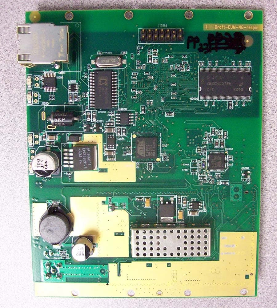
915A Radio (EUM3005A PCB) Photos Top Side with shield on Top side under shield detail Bottom side with shield on Bottom side, shield off, radio detail.
ID Label/Location Info
WaveRider Communications (Canada) Inc. Suite 4, 6110 - 1A Street SW, Calgary, Alberta T2H 0G3 Tel/FAX: 403•253•5366 web: www.waverider.com 27 March 2006 To Whom It May Concern: Reference: FCC ID "OOX-915A" and IC “3225B-915A” Labeling The drawing below represents the label for the 915A, showing the FCC and Industry Canada IDs. This label will appear on all 915A boards. REV.DESCRIPTIONDATEBY 1.50 0.25 Label as shown: Text - Arial 8 pt Black Barcode - IDAutomationSC128S (Code 128) Material - White Polyester Adhesive - Able to withstand -40 to +70C Manufacturer can alter barcode font and text font provided relative locations and text are preserved and text is clearly legible. D C B A 4321 D C B A 4321 to scale 610234 610234 FCC ID: OOX-915A IC: 3225B-915A 2x scale 1Initial Version11-Mar-06LAG 2Correct Temp Range13-Mar-06LAG DESCRIPTION For use on EUM3005A (W/R 002-009) and EUM3006A (002-010) PCBs DRAWN BY LAWRENCE GORDON PAGE 1 OF 1 TITLE 915A Radio PCBA Label FILENAME REVISED 27-Mar-06 610234 610234 FCC ID: OOX-915A IC: 3225B-915A 3Add ID to "FCC ID:"27-Mar-06LAG The location of the label on the board is left to the manufacturer. The following picture shows a typical placement. WaveRider Communications (Canada) Inc. Suite 4, 6110 - 1A Street SW, Calgary, Alberta T2H 0G3 Tel/FAX: 403•253•5366 web: www.waverider.com 610234 610234 FCC ID: OOX-915A IC: 3225B-915A WaveRider Communications (Canada) Inc. Suite 4, 6110 - 1A Street SW, Calgary, Alberta T2H 0G3 Tel/FAX: 403•253•5366 web: www.waverider.com The label show below will be prominently displayed on the outside of the EUM3005A modem. A similar label will be display on any other device containing the 915A board. The label below is approximately 50% larger than the actual label. The label is composed of: MATERIAL - Thermal Transfer Matte Silver Polyester Label Material: 3M P/N 3M7872 ADHESIVE - Acrylic Adhesive: 3M P/N: #350 LINER - #55 Densified Kraft The location of the label on the EUM3005 is shown in the following picture, although with an older model. WaveRider Communications (Canada) Inc. Suite 4, 6110 - 1A Street SW, Calgary, Alberta T2H 0G3 Tel/FAX: 403•253•5366 web: www.waverider.com Your Truly, Lawrence Gordon, Senior Technical Design Lead, WaveRider Communications Inc. Suite 4, 6110 - 1A St. SW, Calgary, Alta, T2H 0G3 Tel/FAX: (403) 253-5366, Tel: (403) 616-5668(cell)
Internal Photos
915A Radio (EUM3005A PCB) Photos Top Side with shield on Top side under shield detail Bottom side with shield on Bottom side, shield off, radio detail.
Operational Description
WaveRider Communications (Canada) Inc. Suite 4, 6110 - 1A Street SW, Calgary, Alberta T2H 0G3 Tel/FAX: 403•253•5366 web: www.waverider.com 915A Functional Overview The 915A is a 900MHz radio module intended to provide connectivity between an end-user’s computer and an Internet Service Provider. It is a single PCB wireless solution based on the Intersil PRISM II Direct Sequence Chip Set. The 915A is functionally equivalent to the EUM3005 (previously certified with FCC ID: OOX-EUM3005), the EUM3006 (OOX-EUM3006) and the MMT9000 (OOX-WMAN) in regards to frequency of operation, output power, and modulation scheme. The 915A is intended for mounting in variety of chassis, including an indoor plastic enclosure and aluminum enclosure for vehicle mounting. Overall functionality The 915A consists of two main sections; the digital and the RF section. Block diagrams for both sections can be found in the document “915A Block Diagrams”. The digital section contains the following functionality: 1. I/O 2. Ethernet PHY 3. Microprocessor/MAC 4. Memory 5. Power Regulation The radio module’s RF section contains the following functionality: 1. Baseband Processor 2. Modulator/Demodulator (with IF synthesizer) 3. RF Synthesizer 4. Up Converter 5. Power Amplifier 6. Low Noise Amplifier (LNA) 7. Down Converter 8. RF VCO 9. IF VCO 10. Reference Oscillator 11. Antenna (RF) Interface During transmission, data obtained by the Microprocessor from the I/O ports, is transferred to the MAC. The MAC reformats the data and places it on the Baseband Processor TX data line. This data is modulated using CCK modulation and then spread using a defined PN code such that the data is sent at a rate of 2.75Mbit/s. The data is preceded by a header that uses DPSK modulation. Two signals are generated, the In-Phase (I) and Quadrature (Q) components. The I & Q signals are sent to the Modulator/Demodulator where they are first…
Text truncated - open the document above for the full version.
Contact Information
Applicant
Lawrence Gordon(Senior Technical Design Lead)
Test Firm
Electronics Test CentreV Mediboina
Technical Specifications
| # | Rule Parts | Frequency Range | Power Output |
|---|---|---|---|
| 1 | 15C | 905 MHz - 925 MHz | 538.00 mW |
Other Applications from Vecima Networks Inc.
OOX-915C
Oct 23, 2007Wireless Transceiver Module
Equipment Class
DTS - Digital Transmission System
OOX-E3K6
May 10, 2006Outdoor Modem
Equipment Class
DTS - Digital Transmission System
OOX-EUM3005
Mar 21, 2005Wireless Modem
Equipment Class
DTS - Digital Transmission System
OOX-EUM3004
Nov 10, 2003Wireless LAN end-users modem
Equipment Class
DTS - Digital Transmission System
OOX-EUM3003
Jan 25, 2003Wireless LAN end-user modem
Equipment Class
DTS - Digital Transmission System