OOX-EUM3003Wireless LAN end-user modem
Vecima Networks Inc.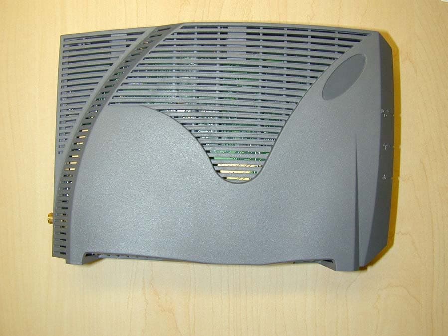
Click to zoom
Application Details
- Equipment Class
- DTS - Digital Transmission System
- Date of Grant
- Jan 25, 2003
- Application Purpose
- Original Equipment
- Date of Application
- Jan 23, 2003
- Equipment Note
- Wireless LAN end-user modem
- Frequency Range
- 902.00000000 - 928.00000000
- Company
- Vecima Networks Inc.
- Country
- Canada
Documents & Files
Document Text
Text extracted from the exhibit documents filed with the FCC. Open a document above to read the original.
Users Manual
LMS4000 900 MHz Radio Network User Guide APCD-LM043-4.0 WaveRider Communications Inc. Software License Agreement This is a legal agreement between you (either an individual or an entity) and WaveRider Communications Inc. for the use of WaveRider computer software, hereinafter the “LICENSED SOFTWARE”. By using the LICENSED SOFTWARE installed in this product, you acknowledge that you have read this license agreement, understand it, and agree to be bound by its terms. You further agree that it is the full and complete agreement between you and WaveRider Communications Inc., superseding all prior writ- ten or verbal agreements of any kind related to the LICENSED SOFTWARE. If you do not understand or do not agree to the terms of this agreement, you will cease using the LICENSED SOFTWARE immedi- ately. 1. GRANT OF LICENSE—This License Agreement permits you to use one copy of the LICENSED SOFTWARE. 2. COPYRIGHT—The LICENSED SOFTWARE is owned by WaveRider Communications Inc. and is protected by copyright laws and international treaty provisions; therefore, you must treat the LICENSED SOFTWARE like any other copyrighted material (e.g., a book or magazine). You may not copy the written materials accompanying the LICENSED SOFTWARE. 3. LIMITS OF FEATURE AVAILABILITY—The LICENSED SOFTWARE is sold with limitations as to certain feature availability and use. These limits are governed by the terms of the purchase agreement. Any actions resulting in the exceeding of these limits is not permitted, and can result in unpredictable performance. 4. OTHER RESTRICTIONS—You may not rent or lease the LICENSED SOFTWARE. You may not reverse engineer, decompile, or disassemble the LICENSED SOFTWARE. 5. LIMITED WARRANTY—The LICENSED SOFTWARE is provided “as is” without any warranty of any kind, either expressed or implied, including, but not limited to, the implied warranties of merchantability and fitness for a particular purpose. The entire risk as to the quality and performance of the LICENSED SOFTWARE is with you, the licensee. If the LICENSED SOFTWARE is defective, you assume the risk and liability for the entire cost of all necessary repair, service, or correction. Some states/jurisdictions do not allow the exclusion of implied warranties, so the above exclusion may not apply to you. This warranty gives you specific legal rights, and you may have other rights, which vary from state/jurisdiction to state/jurisdiction. WaveRider Communications Inc. does not warrant that the functions contained in the LICENSED SOFTWARE will meet your requirements, or that the operation of the LICENSED SOFTWARE will be error-free or uninterrupted. 6. NO OTHER WARRANTIES—To the maximum extent permitted by applicable law, WaveRider Communications Inc. disclaims all other warranties, either express or implied, including, but not limited to, the implied warranties of merchantability and fitness for a particular purpose, with regard to the LICENSED SOFTWARE and the accompanying written materials. 7. NO LIABILITY FOR CONSEQUENTIAL DAMAGES—To the maximum extent permitted by applicable law, in no event shall WaveRider Communications Inc. or its suppliers be liable for any damages whatsoever (including, without limitation, damages for loss of business profits, business interruption, loss of business information, or any other pecuniary loss) arising from the use of or inability to use the LICENSED SOFTWARE, even if WaveRider Communications Inc. has been advised of the possibility of such damages, or for any claim by any other party. Because some states/jurisdictions do not allow the exclusion or limitation of liability for consequential or incidental damages, the above limitation may not apply to you. In no event will WaveRider’s liability exceed the amount paid for the LICENSED SOFTWARE. The following are trademarks or registered trademarks of their respective companies or organizations: Microsoft Windows NT 4.0 Workstation (with Service Pack 6a), Microsoft Access, Microsoft SQL Server, Microsoft SQL Agent / Microsoft Corporation Vircom VOP Radius Server / Vircom Inc. Castlerock SNMPc Server / Castle Rock Computing APS PowerChute PLUS / American Power Conversion Veritas Backup Exec / VERITAS Software © 2002 by WaveRider Communications Inc. All rights reserved. This manual may not be reproduced by any means in whole or in part without the express written permission of WaveRider Communications Canada Inc. ISSUE 4.0, April 2002 Warranty In the following warranty text, “WaveRider®” shall mean WaveRider Communications Inc. This WaveRider product is warranted against defects in material and workmanship for a period ofone (1) yearfrom the date of purchase. During this warranty period WaveRider will, at its option, either repair or replace products that prove to be defective. For warranty service or repair, the product must be returned to a service facility designated by WaveR- ider. Authorization to return products must be obtained prior to shipment. The WaveRider RMA number must be on the shipping documentation so that the service facility will accept the product. The buyer shall pay all shipping charges to WaveRider and WaveRider shall pay shipping charges to return the product to the buyer within Canada or the USA. For all other countries, the buyer shall pay shipping charges as well as duties and taxes incurred in shipping products to or from WaveRider. WaveRider warrants that the firmware designed by it for use with the unit will execute its programming instructions when properly installed on the unit. WaveRider does not warrant that the operation of the unit or firmware will be uninterrupted or error-free. Limitation of Warranty The foregoing warranty shall not apply to defects resulting from improper or inadequate maintenance by the buyer, buyer-supplied interfacing, unauthorized modification or misuse, operation outside the envi- ronmental specifications for the product, or improper site preparation or maintenance. No other warranty is exp…
Text truncated - open the document above for the full version.
Block Diagram
The following are the block diagrams for the RF and digital sections of the EUM3003. The blocks shown are as follows: Top level RF section Ethernet MAC/PHY Microprocessor memory Microprocessor MAC interface 1. Block Diagram 1.1 Top Level Block Diagram MICRO PROCESSOR MICROPROCESSOR MEMORY (FLASH, SDRAM) DSSS BBP MAC MEMORY (FLASH, SRAM) 44MHz REF OSC 7.5V 3.3V 1.5V Linear Regulator ÷ 4 ÷ 2 DC/DC CONVERTER Ethernet MAC/PHY ID ata+/- OData+/- 2 2 RF Deck 11MHz22MHz LED1E LED2E LED1 LED2 LED3 Antenna 1.55V 3.3V 3.3V 3.3V 3.3V 3.3V 7.5V 3.3V Figure 1.1 – Top Level Block Diagram 1.2 RF Section +7.5V DC VRFLO 3.3V 5V Regulator 3.3V Regulator SYN TO RF LO 44MHz_in Front End Filter PA TX RF Image Filter TX Mixer RX Mixer RX RF Image Filter RF LNA PAPE RF LO 975-995 MHz RX IF Filter 1 ANTSEL RFSW RXRFAGC TX RX Switch IF Driver IF Amp RXIF- RXIF+ TXIF- TXIF+ XFER 7.5V PA 902-928 MHz70 MHz 70 MHz 902-928 MHz RXIFAGC VREF TXIFAGC RXQ+/- RXI+/- TXI+/- I/Q MOD/DE - MODULATOR 140 MHz IFLO IFDET TXQ+/- M_LE_IF CAL_EN Buffer Legend Shield wall -3V Regulator -3V PA TX IF Filter TX IF Amp To Antenna XFER 7.5V Supply M_SD_IF_RF M_LE_RF M_SCLK_IF_RF RX IF Filter 2 Voltage Translator RF PA Digital PA Bias Pots M_SCLK_IF_RF M_SD_IF_RF 2 2 2 2 PE1 PE2 M_SD_IF_RF M_SCLK_IF_RF 44MHz_in VIFLO 3.3V Regulator RXRFAGC ANTSEL RFSW M_LE_RF Figure 1.2 – RF Section Block Diagram 1.3 Digital Section 1.3.1 Ethernet MAC/PHY 44 ETHERNET MAC / PHY BLOCK SMSC LAN91C113 ADDR[15..1] INTRO nCS3 nADS Reset nLNK DATA[15..0] LEDB 2 IDATA- ODATA+ ODATA- IDATA+ nRE nWE BE1 BE0 nDATACS ENEEP 2 LED1E LED2E LEDA 15 16 25MHz TPO+ TPO- TPI+ TPI- GND GND GND GND 11 k Ω RBIAS GND 3.3V 3.3V 1.3.1 Ethernet MAC/PHY Block Diagram 1.3.2 Microprocessor Memory (FLASH,SDRAM) GROUND D ATA[31..0] PROCESSOR MEMORY BLOCK ADDR[24..0] D[15..0] A[24..1] 3.3V /C S0 /O E /W E A [20..10] A21 A22 TC59S6432CFT801W K1 SDRAM RC28F640JBA120 (64M) OR MBM29LV320BE90NT (32M) MBM29LV160BE90NT (16M) FLASH / BYTE D[15..0] A[24..1] A0 VPEN STS /R P /D Q M[3..0] TO G PIO SA_RST_OUT D ATA[31..0] D [31...0] GROUND /C AS /R AS /SDCS 0 /W E /C KE /C LK BA1 BA0 D[31..0] A[10..0] For the 32M and 16M flash, the address bus is shifted by one and A0 is not used. VPEN 3.3V 3 1.3.2 Microprocessor Memory Block Diagram 1.3.3 Microprocessor /WAIT /IREG DATA[15..0] ADDR[15..0] /IOIS16 RESET /CE1 /CE2 /IOWR /IORD /WE /OE /REG /INPACK 16 16 To MAC DATA[31..0] 32 ADDR[24..0] 25 RF PA To RF 3.6864MHz32.768kHz ADDR[15..1] INTRO nCS3 Rese t DATA[15..0] nRE nWE 15 16 LED2 LED1 3.3V 3 LED3 To Ethernet To Memory 1.5V 1.3.4 MAC Interface 3 PAPE TO PROCESSOR 11 MHz /WAIT /IREG DATA[15..0] ADDR[15..0] M_SD_IF_RF M_SCLK_IF_RF M_LE_RF M_LE_IF A[16..0] /OE /WE D[7..0] /OE/WE A[16..0 ] D[7..0] CY7C1019V33 (SRAM) MAC MEMORY MAC BLOCK - PCMCIA SOCKET 1 TO RF /IOIS16 RESET /CE1 /CE2 /IOWR /IORD /WE /OE /REG /INPACK PE1 PE2 CAL_EN RFSW 17 8 2 DSSS BBP 22 MHz AT76C502A IFDET ANTSEL RXRFAGC TXI ± TXQ ± VREF RXI ± RXQ ± TXIFAGC RFIFAGC 2 2 2 2 2 MUX 1.3.3 MAC Interface Block Diagram
Operational Description
APCD-LM043-5.0-D191 Appendix G Antenna Guidelines WARNING! Antennas and associated transmission cable must be installed by qualified personnel, and external antennas must be properly grounded. Incorrect termination of the antenna port can permanently damage the EUM. WaveRider assumes no liability for failure to adhere to this recommendation or to recognized general safety precautions. The CCU and EUM have been certified for use with Omni, Patch, Yagi, and Dipole Reflector antenna types, in addition to the WaveRider Diversity Antenna.Ta b l e 5 5includes examples of each of the recommended antenna types, as well as their associated maximum antenna gains. Table 55 CCU, EUM Supported Antennas Antenna system gain is the net gain of the system. In other words, it is the antenna gain minus the insertion loss due to cabling, connectors, filters, surge protectors, and other hardware components. During installation, you must verify that the antenna system does not exceed the maximum allowable certified antenna system gain, which is 8.8 dBi. Calculate the antenna system gain by adding the value of the insertion loss for each component of the antenna system, excluding the antenna, and subtracting the total of that sum from the antenna gain. You can measure the insertion loss of the components, and the Antenna TypeMaximum Antenna Gain Omni5.1dBi Patch8.5 dBi Yagi13.0dBi Panel12.0dBi 192APCD-LM043-5.0-D antenna gain, at the frequency of interest, or obtain it by referencing the manufacturer’s supplied literature. WaveRider Guidelines for outdoor installation are: •select a cable of type and length so that cable loss is 3.5dB, including connectors. •use a surge protector, which has about 0.1 db loss, •use a WaveRider jumper cable to connect the modem to the exterior cable or surge protector. The jumper cable has a loss of 1 dB. For example, with a Yagi antenna system, 15 m of cable, a surge protector, and a jumper cable (from modem to surge protector), you would calculate the following antenna system gain: •Antenna Gain: 13.0 dBi •Insertion loss: •External Cable:- 3.5 dB •Surge Protector:- 0.1dB •Jumper Cable:- 1.0 dB •-4.6dBi The antenna gain (13.0 dBi) minus the total insertion loss (4.6 dBi), yields an antenna system gain of 8.4 dBi, which is a valid antenna configuration, because the antenna system gain is lower than the maximum permissible value of 8.8 dBi. WARNING! To prevent equipment damage, you must use the WaveRider proprietary WCM connector to connect transmission line and antennas to the EUM3000. WARNING! Use of an outdoor antenna with the EUM requires professional installation, in accordance with FCC guidelines. WARNING! Antennas used with the EUM must not present a short to ground at the EUM antenna port. Contact the WaveRider Customer Support Centre for more information.
Operational Description
Model 305-0122 305-0120 305-0121 3dB Beamwidth, Degrees E-Plane 40 70 55 3dB Beamwidth, Degrees H-Plane 45 100 65 Connector (female) N N N Frequency, MHz 896-940 896-980 896-940 Front to Back Ratio, dB 20 15 18 Gain dBi 13 8.2 11 Length in.(cm) 41-7/16(105.2) 13(33) 24-3/4(62.9) No. Elements 10 4 6 Weight, lb(kg) 2.31(1.04) 1.12(.50) 1.62(.73) W/ 1/2in. Ice mph(kph) 100(161) 100(161) 100(161) Wind Surface Area ft(m) sq 0.38(0.035) 0.11(0.01) 0.26(0.024) Wind Survival mph(kph) 125(200) 125(200) 125(200) www.waverider.com 416 502 8657 These Yagi antennas are DC Blocked specifically for outdoor use with WaveRider’s EUM3000 CPE Equipment. Each comes complete with a U-Bolt mounting kit. Jumper cables are sold separately. 900 MHz WaveRider EUM3000 YAGI Antennas with DC blocked Yagi Antenna
Operational Description
Murandi Communications Ltd. Innovative Radio Frequency Solutions Murandi Communications Ltd. Suite 300, 6715 - 8th St. NE, Calgary, Alberta, Canada, T2E 7H7 Tel: (403) 777-9988email [email protected] Fax: (403) 777-9989www.murandi.com EUM3003 Functional Overview The EUM3003 is a 900MHz radio module intended to provide connectivity between an end-user’s computer and an Internet Service Provider. It is a single PCB wireless solution based on the Intersil PRISM II Direct Sequence Chip Set. The EUM3003 is functionally equivalent to the EUM3000 (previously certified with FCC ID: OOX-LMS3000) in regards to frequency of operation, output power, and modulation scheme. The main difference from the user’s perspective is that RS232 and USB interfaces are not available on the EUM3003. Changes to the RF synthesizer in the radio circuitry of the EUM3003 require that it be resubmitted for certification. Overall functionality The two block diagrams, one representing the RF functionality, the other the Digital functionality of the radio module are located in Figures 1 and 2. The digital section contains the following functionality: 1. I/O 2. Ethernet Controller 3. Microprocessor 4. MAC 5. Memory 6. Reference Oscillator 7. Power Regulation The radio module’s RF section contains the following functionality: 1. Baseband Processor 2. Modulator/Demodulator (with IF synthesizer) 3. RF Synthesizer 4. Up Converter 5. Power Amplifier 6. Low Noise Amplifier (LNA) 7. Down Converter 8. RF VCO 9. IF VCO 10. Antenna (RF) Interface During transmission, data obtained by the Microprocessor from the I/O ports, is transferred to the MAC. The MAC reformats the data and places it on the Baseband Processor TX data line. This data is modulated using CCK modulation and then spread using a defined PN code such that the data is sent at a rate of 2.75Mbit/s. The data is preceded by a header that uses DPSK modulation. Two signals are generated, the In-Phase (I) and Quadrature (Q) components. The I & Q signals are sent to the Modulator/Demodulator where they are first filtered and then modulated with the IF frequency (70 MHz). The IF oscillator generates a 140 MHz signal which is divided by two inside the Modulator/Demodulator and used to modulate the I & Q signals. The final IF signal of 70 MHz is then sent to the Up converter. The Up converter will shift this signal to the RF frequency for the channel programmed in the synthesizer, for operation within the 902-928 MHz ISM band. In the final stage, this signal is amplified to produce +26 dBm RF power output as measured at the output of the antenna port. Page 2Printed: 12/30/02 11:35 AM Murandi Communications Ltd. Suite 300, 6715 - 8th St. NE, Calgary, Alberta, Canada, T2E 7H7 Tel: (403) 777-9988Fax: (403) 777-9989 In receive mode, the radio signal is amplified by the LNA, and then sent to the Down converter. The Down converter converts this signal from the 902-928 MHz range to the IF frequency, 70 MHz. The Modulator/Demodulator then converts the signal to baseband and splits the signal into its I & Q components, before sending it to the Baseband Processor. Finally, the Baseband Processor despreads and demodulates the data contained in the CCK format, and places it on the RX data line to the MAC. The MAC modifies the data, then transfers it to the Microprocessor which reformats the information and sends it out the I/O ports. The RF and IF Local Oscillator signals are generated using the synthesizers and voltage controlled oscillators. The RF synthesizer is programmed with the desired RF channel frequency plus the IF frequency. The IF synthesizer in the Modulator/Demodulator is programmed with 140MHz. The baseband processor and the synthesizer are driven from a common 44 MHz oscillator to control the timing of these chips. Example (for Channel 1 operation) : RF IF LO 905 MHz + 70 MHz = 975 MHz Antennas The antenna (RF) connector is a non-standard wide-barrel SMA connector and is connected to one of two antenna configurations: 1) A diversity antenna 2) A Yagi, Panel, or Patch antenna through a 50-ohm impedance matched transmission line (Times Microwave LMR-200) The unit was qualified with 4 different antennas types; Yagi, Panel, Patch and Diversity. For output powers of 26dBm, the antenna system gains shall be 10 dBi or less in order to meet the regulatory requirements of 15.247(b)(4). However, to meet power density requirements of 1.1310, the antenna system gain is limited to 8.8dBi. The following table shows antenna gains for each type of antenna and the associated antenna system gain including cable losses for typical installations. AntennaCableAnt. System #ModelTypeManufacture Gain (dBi) ModelLengthLoss (dB)Gain (dBi) 1SPPC12-WR PanelSuperpass12LMR-200 15 m4.97.1 2ASTPCA09 PatchAstron8.5LMR-200 7.52.56.0 3PC8910NYagiCushcraft13LMR-200 15 m4.98.1 4WaveRiderDiv Ant.6.2--0.06.2 Page 3Printed: 12/30/02 11:35 AM Murandi Communications Ltd. Suite 300, 6715 - 8th St. NE, Calgary, Alberta, Canada, T2E 7H7 Tel: (403) 777-9988Fax: (403) 777-9989 +7.5V DC VRFLO 3.3V 5V Regulator 3.3V Regulator SYN TO RF LO 44MHz_in Front End Filter PA TX RF Image Filter TX Mixer RX Mixer RX RF Image Filter RF LNA PAPE RF LO 975-995 MHz RX IF Filter 1 ANTSEL RFSW RXRFAGC TX RX Switch IF Driver IF Amp RXIF- RXIF+ TXIF- TXIF+ XFER 7.5V PA 902-928 MHz70 MHz 70 MHz 902-928 MHz RXIFAGC VREF TXIFAGC RXQ+/- RXI+/- TXI+/- I/Q MOD/DE - MODULATOR 140 MHz IFLO IFDET TXQ+/- M_LE_IF CAL_EN Buffer Legend Shield wall -3V Regulator -3V PA TX IF Filter TX IF Amp To Antenna XFER 7.5V Supply M_SD_IF_RF M_LE_RF M_SCLK_IF_RF RX IF Filter 2 Voltage Translator RF PA Digital PA Bias Pots M_SCLK_IF_RF M_SD_IF_RF 2 2 2 2 PE1 PE2 M_SD_IF_RF M_SCLK_IF_RF 44MHz_in VIFLO 3.3V Regulator RXRFAGC ANTSEL RFSW M_LE_RF Figure 1 RF Section Block Page 4Printed: 12/30/02 11:35 AM Murandi Communications Ltd. Suite 300, 6715 - 8th St. NE, Calgary, Alberta, Canada, T2E 7H7 Tel: (403) 777-9988Fax: (403) 777-9989 MICRO PROCESSOR MICROPROCESSOR MEMORY…
Text truncated - open the document above for the full version.
Operational Description
Murandi Communications Ltd. Innovative Radio Frequency Solutions Murandi Communications Ltd. Suite 240, 6715 - 8th St. NE, Calgary, Alberta, Canada, T2E 7H7 Tel: (403) 777-9988Fax: (403) 777-9989 WaveRider Technical Specifications for the EUM3000 Antenna Rev. 2 - February/01 1. Table of Contents 1.Table of Contents .................................................................................................................... 1 2.References .............................................................................................................................. 1 3.Revision Notes ........................................................................................................................ 1 4.Introduction.............................................................................................................................. 1 5.Technical Specifications.......................................................................................................... 2 5.1 Physical............................................................................................................................... 2 5.2 Electrical.............................................................................................................................. 2 5.3 Environmental ..................................................................................................................... 2 5.4 Other Requirements............................................................................................................ 3 6.Interface Specifications ........................................................................................................... 3 6.1 Diversity Antenna Connection............................................................................................. 3 2. References 1. EUM3000 Modem Development Specification, December 1999. 2. Minutes of March 10, 2000 meeting (EUM3000&CCU3000 Packaging). 3. Draft Technical Specification review at WaveRider, Mar 27, 2000. 4. Email from Ivan Rodrigues 8:23 PM Mar 30, 2000. 3. Revision Notes 16-May-00 - Creation date. 4. Introduction WaveRider Inc. is developing a digital wireless Modem providing connectivity between an end- user’s computer and an Internet Service Provider. The system consists of a Radio Section, a Digital Section, and an antenna unit. The wireless link is based upon the Intersil PRISM-II chipset and operates at raw data rates of up to 2.75Mbps. The modulation scheme is Complementary Code Keying (CCK) over a 5.5 MHz channel bandwidth, with a DPSK header which is at a lower data rate. This document presents the Technical Specifications for the antenna unit, and, in conjunction with the EUM Antenna Acceptance Test Plan, forms the basis for determining whether or not the antenna meets the contractual obligations. Page 2Printed: 26/02/01 4:40 PM Murandi Communications Ltd. Suite 240, 6715 - 8th St. NE, Calgary, Alberta, Canada, T2E 7H7 Tel: (403) 777-9988Fax: (403) 777-9989 5. Technical Specifications 5.1 Physical SubjectSpecificationsRef.Comments Housings and Mount • Window, desktop and/or wall mountable with min 1 axis swivel (azimuth) • Injection molded • Snap together clam shell • 6” x 6” x 2” max. • Product label in a hidden location 2,3Any dimension may be modified ± 0.5” to accommodate design optimization or housing dimensions. WeightNot Specified3Based on Industrial Design. 5.2 Electrical SubjectSpecificationsRef.Comments Peak Gain (in-phase/phase- shifted mode) 4.4 dBi / 0.7 dBi Total 6 dBi / 2.3 dBi Antenna Only (typical, vertical polarization) Frequency Range902 – 928 MHz Cable • 50 Ω • 1.6 dB typical loss • 10 feet max. 3 Power handling+30 dBm min. VSWR2:1 min. Diversity Control Signal 7.5 V for Pattern A (phase-shifted mode) 6.0 V for Pattern B (in-phase mode) Diversity< 0.5 Correlation CoefficientPattern Diversity, switching between two high gain options. 5.3 Environmental SubjectSpecificationsRef.Comments Operating Temperature 10 C to 40 C(EUM)3 Storage Temperature-40 C to 70 C1 Operating Relative Humidity 0 to 95% non condensing1 Shock (Packaged)20 G @ 11 msec. 2 directions on 3 axis Non operating. Vibration (Packaged)1 Gpp @ 5-500 Hz swept sine on 3 axis Non operating. Page 3Printed: 26/02/01 4:40 PM Murandi Communications Ltd. Suite 240, 6715 - 8th St. NE, Calgary, Alberta, Canada, T2E 7H7 Tel: (403) 777-9988Fax: (403) 777-9989 SubjectSpecificationsRef.Comments ESDNot Specified3,4Design practices consistent with other computer peripherals will be implemented 5.4 Other Requirements SubjectSpecificationsRef.Comments MTBFAt least 26,000 hours1 Service Life3 years1 6. Interface Specifications 6.1 Diversity Antenna Connection PinNameDescription Inner 50 Ω RF Port (Bi- directional) Antenna RF Input/Output and DC: • 902 – 928 MHz • RF Input/Output • Nominal 50 Ω (VSWR 2:1) • DC signal to switch between diversity antennas • Max torque equal to the connector manufacturer’s specification • No special tools required for installation • Hand installable • Some open/short circuit protection will be provided by current limiting the PA Outer RF Subsystem Ground (Bi-directional) GND Low impedance ground
Operational Description
Panel Antenna
RF Exposure Info
Murandi Communications Ltd. Innovative Radio Frequency Solutions Murandi Communications Ltd. Suite 300, 6715 - 8th St. NE, Calgary, Alberta, Canada, T2E 7H7 Tel: (403) 777-9988email [email protected] Fax: (403) 777-9989www.murandi.com EUM3003 RF Exposure Calculations As per OET Bulliten 65 – Evaluating Compliance with FCC Guidelines for Human Exposure to Radiofrequency Electromagnetic Fields – Edition 97-01, the maximum power density allowed for general population/uncontrolled exposure is f/1500 where f is the frequency of operation in MHz. Calculating for the lowest frequency of operation (905MHz), the maximum power density allowed is 0.603 mW/cm 2 . The power density is calculated as follows: S = (P*G)/(4*pi*R 2 ) where: S = power density in mW/cm 2 P = power at the antenna connector in mW G = linear system gain of the antenna R = separation from antenna (cm) As per the User’s manual, all antennas for the EUM (indoor and outdoor) must be fix-mounted such that there is at least 20cm of separation between the antenna and a person. For an output power of 26dBm (398mW), and a separation of 20cm, the maximum allowable antenna system gain is 8.8dBi. The antenna system gain for all antenna types shown in “EUM3003 Functional Overview” are less than the limit of 8.8dBi, therefore meeting the FCC requirements for human exposure to RF radiation.
Test Report
This report shall not be reproduced, except in full, without prior written approval of MPB Technologies Inc. Test Report Prepared By: Electronics Test Centre 27 East Lake Hill Airdrie, Alberta Canada T2B 2B7 [email protected] phone: (403) 912-0037 fax: (403) 912-0083 MPBT Report No.: m01e2708Rev: 2Date: 16 Jauary 2003 Report for Emissions Testing of the Waverider EUM3003 wireless modem In accordance with FCC Part 15, Subpart C (2000). Test Personnel:David Raynes, James MacKay Prepared for:Waverider Communications Inc. 255 Consumers Road Suite 500 Toronto, Ontario Canada M2J 1R4 _________________________ Client Acceptance Authorized Signatory _________________________ David Raynes, James MacKay Laboratory Supervisor Electronics Test Centre (Airdrie) Authorized Signatory Test Sample: EUM3003 FCC Part 15, Subpart C (2000)Report No.:m01e2708 rev. 2 This report shall not be reproduced, except in full, without prior written approval of MPB Technologies Inc. TABLE OF CONTENTS 1.0INTRODUCTION 1.1SCOPE 1.2APPLICANT 1.3APPLICABILITY 1.4TEST SAMPLE DESCRIPTION 1.5GENERAL TEST CONDITIONS AND ASSUMPTIONS 1.6SCOPE OF TESTING 1.6.1 VARIATIONS IN TEST METHODS 1.6.2 EMISSIONS MEASUREMENTS 1.6.3TEST SAMPLE MODIFICATIONS 2.0ABBREVIATIONS 3.0MEASUREMENT UNCERTAINTY 4.0TEST CONCLUSION 4.1 CONDUCTED EMISSIONS ON AC LINES 4.2CONDUCTED EMISSIONS MEASURED AT ANTENNA PORT 4.3 RADIATED EMISSIONS INCLUDING RESTRICTED BANDS OF OPERATION 5.0TEST FACILITY 5.1 LOCATION 5.2 GROUNDING PLAN 5.3POWER 5.4 EMISSIONS PROFILE 5.5 TEST CONFIGURATION 5.5.1TABLETOP EQUIPMENT 5.5.2RACK MOUNT 6.0TEST EQUIPMENT 6.1 RADIATED EMISSIONS 6.2 CONDUCTED EMISSIONS 6.3 CALIBRATION APPENDIX A:Test Sample Description:EUM3003 Test Sample: EUM3003 FCC Part 15, Subpart C (2000)Report No.:m01e2708 rev. 2 This report shall not be reproduced, except in full, without prior written approval of MPB Technologies Inc. 1.0 INTRODUCTION 1.1SCOPE The purpose of this report is to present the findings and results of compliance testing performed in accordance with CFR Title 47 FCC Part 15, Subpart C, Intentional Radiators. 1.2APPLICANT This test report has been prepared for Waverider Communications Inc., located in Toronto, Ontario, Canada. 1.3APPLICABILITY All test procedures, limits, and results defined in this document apply to the Waverider Communications Inc. EUM3003 unit, referred to herein as the Equipment Under Test (EUT). The results contained in this report relate only to the item tested. This report does not imply product endorsement by A2LA, or the Canadian or US governments. 1.4TEST SAMPLE DESCRIPTION The test sample provided for testing was a EUM3003: Product Type:wireless modem Model Number:EUM3003 Serial Number:n/a Cables:ethernet, power, RF to antenna Power Requirements:120 VAC 60 Hz to AC-DC power adaptor Peripheral Equipment: Personal Computer More detailed information is provided by Waverider Communications Inc. in Appendix A. 1.5GENERAL TEST CONDITIONS AND ASSUMPTIONS The EUT was set up and exercised using the configurations, modes of operation and arrangements defined in this report only. All inputs and outputs to and from other equipment associated with the EUT were adequately simulated. Where relevant, the EUT was only tested using the monitoring methods and test criteria defined in this report. Environmental conditions are recorded for each test. Test Sample: EUM3003 FCC Part 15, Subpart C (2000)Report No.:m01e2708 rev. 2 This report shall not be reproduced, except in full, without prior written approval of MPB Technologies Inc. 1.6SCOPE OF TESTING Testing was performed in accordance with FCC Part 15 Subpart C (2000), and ANSI C63.4 (1992). 1.6.1VARIATIONS IN TEST METHODS There were no variations from the test procedures outlined above. 1.6.2MARGINAL EMISSIONS MEASUREMENTS As noted in Section 4, some emissions were measured to be within -6 dB of the specified limit: 1.6.3TEST SAMPLE MODIFICATIONS The EUT, EUM3003, underwent the following equipment modifications during test performance: A Ferrico™ p/n NF-65 clamp-on ferrite bead was installed on the LAN cable next to the connector. 2.0 ABBREVIATIONS AP-Average Peak CE-Conducted Emissions E -Field - Electric Field H-Field - Magnetic Field N/T-Not Tested N/A-Not Applicable PK-Peak QP-Quasi Peak RE-Radiated Emissions 3.0 MEASUREMENT UNCERTAINTY For Radiated E-Field Emissions and Conducted Emissions, the uncertainties in the measurements were calculated using the methods outlined in the NAMAS document, NIS81: May 1984. Frequency= ± 1 kHz Amplitude (RE)= ± 4.01 dB Amplitude (CE)= ± 3.25 dB Test Sample: EUM3003 FCC Part 15, Subpart C (2000)Report No.:m01e2708 rev. 2 This report shall not be reproduced, except in full, without prior written approval of MPB Technologies Inc. 4.0 TEST CONCLUSION The EUT was subjected to the follo…
Text truncated - open the document above for the full version.
Contact Information
Applicant
Lawrence Gordon(Senior Technical Design Lead)
Test Firm
Electronics Test CentreV Mediboina
Technical Specifications
| # | Rule Parts | Frequency Range | Power Output |
|---|---|---|---|
| 1 | 15C | 902 MHz - 928 MHz | 398.00 mW |
Other Applications from Vecima Networks Inc.
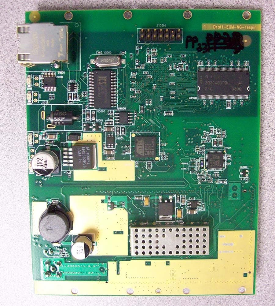
OOX-915C
Oct 23, 2007Wireless Transceiver Module
Equipment Class
DTS - Digital Transmission System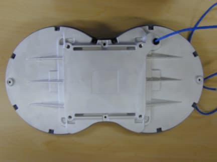
OOX-E3K6
May 10, 2006Outdoor Modem
Equipment Class
DTS - Digital Transmission System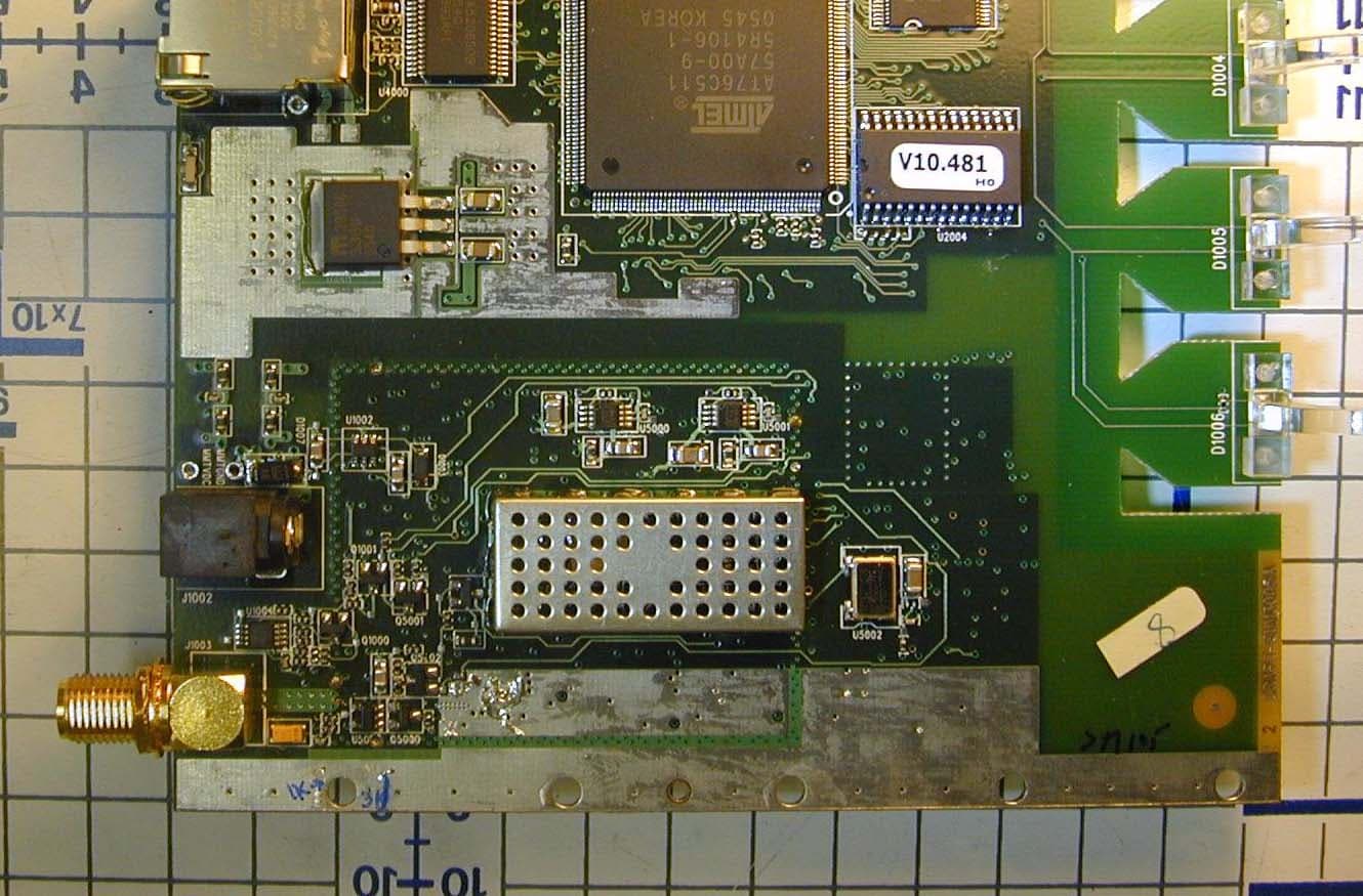
OOX-915A
Mar 27, 2006Radio Module
Equipment Class
DTS - Digital Transmission System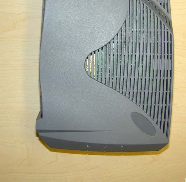
OOX-EUM3005
Mar 21, 2005Wireless Modem
Equipment Class
DTS - Digital Transmission System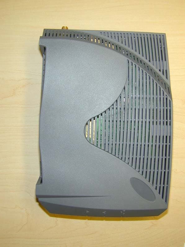
OOX-EUM3004
Nov 10, 2003Wireless LAN end-users modem
Equipment Class
DTS - Digital Transmission System