OOX-EUM3004Wireless LAN end-users modem
Vecima Networks Inc.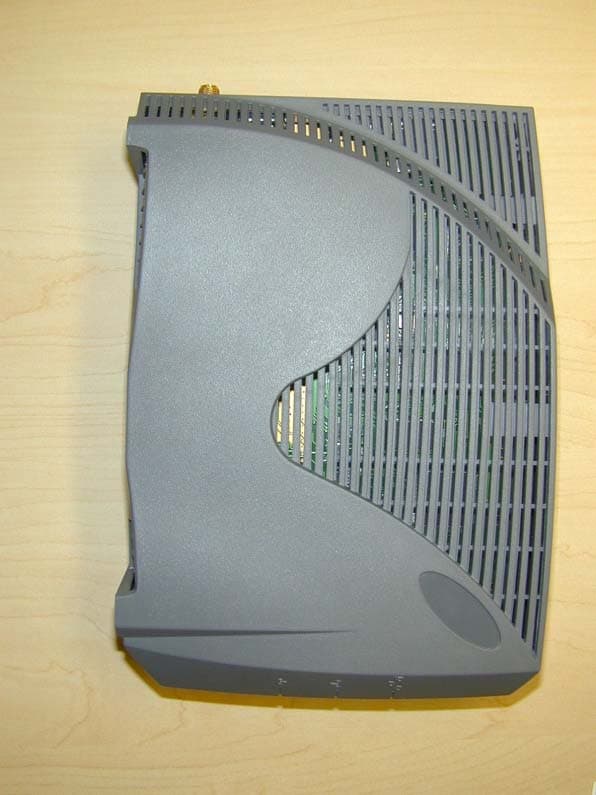
Click to zoom
Application Details
- Equipment Class
- DTS - Digital Transmission System
- Date of Grant
- Nov 10, 2003
- Application Purpose
- Original Equipment
- Date of Application
- Nov 10, 2003
- Equipment Note
- Wireless LAN end-users modem
- Frequency Range
- 902.00000000 - 928.00000000
- Company
- Vecima Networks Inc.
- Country
- Canada
Documents & Files
Document Text
Text extracted from the exhibit documents filed with the FCC. Open a document above to read the original.
Users Manual
156APCD-LM043-8.0 (DRAFT C) 9: Installing the EUM 9.4.9 Obtaining Valid IP Addresses for the End-user’s PC To obtain IP addresses for the end-user’s PC, including the PC IP address, Gateway IP address, and DNS server address, the PC must request an update from the DHCP server. This procedure varies depending on which operating system is running on the end-user’s PC, but a general method is outlined as follows. NOTE: The subscriber PC may obtain a dynamic IP through DHCP, or it may use a static IP and DNS server. To Obtain a Valid IP Address for the End-user’s PC (Windows XP) 1. Open a command prompt window. 2. At the prompt, type ipconfig/release and press Enter. 3. Type ipconfig/renew and press Enter. 4. If no error messages are returned, the WISP network has successfully provided an IP address to the end-user’s PC. 9.4.10 Testing the Data Link The fact that the IP address was successfully obtained indicates that the data link from the PC to the WISP's network is functioning properly. WaveRider recommends more thorough testing of the EUM-to-CCU data link, as outlined below. These tests can also be used to troubleshoot simple problems if DHCP access is not available. There are several tools available for testing the quality of the link between the end-user PC and the WISP network. The most important tool is the “file get” test, which tests the quality of the data link. You can also use the ping command to progressively test presence of the data link. The procedures for running the “file get” throughput tests and “ping” data link tests are described below. To Run a “File Get” Throughput Test From the EUM 1. Open the EUM console, as described in Access Interface on page 221. 2. At the prompt, type file get <ccu_ip_address>, and press Enter. WaveRider Communications, Inc. LMS3000 Password: 60:ff:fe> file get 192.168.1.21 Enter password: file transfer started (press 'qqq' to abort)... bytes processed: 2097152 at 829 kbps file transfer complete Transfered "/tffs0/null" Okay. 60:ff:fe> To Run a “File Get” Throughput Test From the CCU 1. Establish a Telnet connection to the CCU. 2. At the prompt, type file get <eum_ip_address>, and press Enter. 9: Installing the EUM APCD-LM043-8.0 (DRAFT C)157 WaveRider Communications, Inc. LMS3000 Password: 60:03:3a> file get 192.168.10.250 Enter password: file transfer started (press 'qqq' to abort)... by 2097152 at 183 kbps24 at 201 kbps file transfer complete Transfered "/tffs0/null" Okay. 60:03:3a> The following three tests use the “ping” command to progressively test the data link. To Test the Data Link from the End-user’s PC to the EUM 1. Ping the EUM’s IP address from the end-user’s PC, as follows: •Open a DOS window in the end-user’s PC. •At the command prompt, type ping <aaa.bbb.ccc.ddd>, where <aaa.bbb.ccc.ddd> is the IP address of the EUM and press Enter. 2. If there is no response, check the following: •PC IP address settings. •Ethernet crossover cable between the EUM and the end-user’s PC, to ensure that the pins have not been damaged. 3. If there is a response, but with errors, check the Ethernet crossover cable. To illustrate data link testing between the PC and the EUM, consider the sample configuration shown in Figure 60. Figure 60 Sample Configuration — Testing the Data Link Ethernet crossover cabl e EUM Antenna Gateway Router Internet Radio Link End-user's Premises End-user's PC IP Address 172.16.6.1 Net Mask 22 Gateway IP 172.16.4.1 EUM3000 IP Address 172.16.4.2 Net Mask 22 Gateway IP 172.16.4.1 CCU3000 Radio IP Address 172.16.4.1 Net Mask 22 158APCD-LM043-8.0 (DRAFT C) 9: Installing the EUM Using the sample configuration shown in Figure 60, confirm the connection between the end- user’s PC and the EUM as demonstrated below: This is what successful ping from the end-user’s PC to the EUM looks like: C:\>ping 172.16.6.1 Pinging 172.16.6.1 with 32 bytes of data: Reply from 172.16.6.1: bytes=32 time<10ms TTL=64 Reply from 172.16.6.1: bytes=32 time<10ms TTL=64 Reply from 172.16.6.1: bytes=32 time<10ms TTL=64 Reply from 172.16.6.1: bytes=32 time<10ms TTL=64 Ping statistics for 172.16.6.1: Packets: Sent = 4, Received = 4, Lost = 0 (0% loss), Approximate round trip times in milli-seconds: Minimum = 0ms, Maximum = 0ms, Average = 0ms C:\> This is what an unsuccessful ping from the end-user’s PC to the EUM looks like: C:\>ping 172.16.10.1 Pinging 172.16.10.1 with 32 bytes of data: Request timed out. Request timed out. Request timed out. Request timed out. Ping statistics for 172.16.10.1: Packets: Sent = 4, Received = 0, Lost = 4 (100% loss), Approximate round trip times in milli-seconds: Minimum = 0ms, Maximum = 0ms, Average = 0ms C:\> Testing the Data Link from the End-user’s PC to the Network Once the connection from the PC to the EUM is confirmed, ping the EUM gateway address from a PC DOS window. Ping with short packets first to confirm function, and then with long packets (1472 byte packets) to confirm performance. Errors observed on pings with long packets indicate a high error rate on the channel, caused by low signal levels or interference. To Ping a CCU with the Maximum Packet Size 1. Open a DOS window. 2. At the command prompt, type ping <aaa.bbb.ccc.ddd> -t -L 1472, where <aaa.bbb.ccc.ddd> is the CCU radio IP address and press Enter. 3. Press Ctrl+c to end the test. NOTE: If this test fails, but pinging the CCU with the default packet size succeeds, then the connection is working but is not operating at maximum capacity, possibly due to poor antenna placement or orientation. 9: Installing the EUM APCD-LM043-8.0 (DRAFT C)159 This following example uses the sample configuration shown in Figure 60: Pinging the CCU from the end-user’s PC (with maximum packet size): C:\>ping 172.16.4.1 -t -l 1472 Pinging 172.16.4.1 with 1472 bytes of data: Reply from 172.16.4.1: bytes=1472 time=40ms TTL=64 Reply from 172.16.4.1: bytes=1472 time=81ms TTL=64 Reply from 172.16.4.1: bytes=1472 time=80ms TTL=64 Reply from 172.16.4.1: bytes=1472 time=40ms TTL=64 Reply…
Text truncated - open the document above for the full version.
Users Manual
LMS4000 900 MHz Radio Network User Guide APCD-LM043-8.0 (DRAFT C) iiAPCD-LM043-8.0 (DRAFT C) : WaveRider Communications Inc. Software License Agreement This is a legal agreement between you (either an individual or an entity) and WaveRider Communications Inc. for the use of WaveRider computer software, hereinafter the “LICENSED SOFTWARE”. By using the LICENSED SOFTWARE installed in this product, you acknowledge that you have read this license agreement, understand it, and agree to be bound by its terms. You further agree that it is the full and complete agreement between you and WaveRider Communications Inc., superseding all prior written or verbal agreements of any kind related to the LICENSED SOFTWARE. If you do not under- stand or do not agree to the terms of this agreement, you will cease using the LICENSED SOFTWARE immediately. 1. GRANT OF LICENSE—This License Agreement permits you to use one copy of the LICENSED SOFTWARE. 2. COPYRIGHT—The LICENSED SOFTWARE is owned by WaveRider Communications Inc. and is protected by copyright laws and international treaty provisions; therefore, you must treat the LICENSED SOFTWARE like any other copyrighted material (e.g., a book or magazine). You may not copy the written materials accompanying the LICENSED SOFTWARE. 3. LIMITS OF FEATURE AVAILABILITY—The LICENSED SOFTWARE is sold with limitations as to certain feature availability and use. These limits are governed by the terms of the purchase agreement. Any actions resulting in the exceeding of these limits is not permitted, and can result in unpredictable performance. 4. OTHER RESTRICTIONS—You may not rent or lease the LICENSED SOFTWARE. You may not reverse engineer, decompile, or disassemble the LICENSED SOFTWARE. 5. LIMITED WARRANTY—The LICENSED SOFTWARE is provided “as is” without any warranty of any kind, either expressed or implied, including, but not limited to, the implied warranties of merchantability and fitness for a particular purpose. The entire risk as to the quality and performance of the LICENSED SOFTWARE is with you, the licensee. If the LICENSED SOFTWARE is defective, you assume the risk and liability for the entire cost of all necessary repair, service, or correction. Some states/jurisdictions do not allow the exclusion of implied warranties, so the above exclusion may not apply to you. This warranty gives you specific legal rights, and you may have other rights, which vary from state/jurisdiction to state/jurisdiction. WaveRider Communications Inc. does not warrant that the functions contained in the LICENSED SOFTWARE will meet your requirements, or that the operation of the LICENSED SOFTWARE will be error-free or uninterrupted. 6. NO OTHER WARRANTIES—To the maximum extent permitted by applicable law, WaveRider Communications Inc. disclaims all other warranties, either express or implied, including, but not limited to, the implied warranties of merchantability and fitness for a particular purpose, with regard to the LICENSED SOFTWARE and the accompanying written materials. 7. NO LIABILITY FOR CONSEQUENTIAL DAMAGES—To the maximum extent permitted by applicable law, in no event shall WaveRider Communications Inc. or its suppliers be liable for any damages whatsoever (including, without limitation, damages for loss of business profits, business interruption, loss of business information, or any other pecuniary loss) arising from the use of or inability to use the LICENSED SOFTWARE, even if WaveRider Communications Inc. has been advised of the possibility of such damages, or for any claim by any other party. Because some states/jurisdictions do not allow the exclusion or limitation of liability for consequential or incidental damages, the above limitation may not apply to you. In no event will WaveRider’s liability exceed the amount paid for the LICENSED SOFTWARE. : APCD-LM043-8.0 (DRAFT C)iii The following are trademarks or registered trademarks of their respective companies or organizations: Castlerock SNMPc Server / Castle Rock Computing Adobe Acrobat © 2002-2003 by WaveRider Communications Inc. All rights reserved. This manual may not be reproduced by any means in whole or in part without the express written permission of WaveRider Communications Canada Inc. RELEASE 8.0, August 2003 ivAPCD-LM043-8.0 (DRAFT C) : Warranty In the following warranty text, “WaveRider®” shall mean WaveRider Communications Inc. This WaveRider product is warranted against defects in material and workmanship for a period of one (1) year from the date of purchase. During this warranty period WaveRider will, at its option, either repair or replace products that prove to be defective. For warranty service or repair, the product must be returned to a service facility designated by WaveR- ider. Authorization to return products must be obtained prior to shipment. The WaveRider RMA number must be on the shipping documentation so that the service facility will accept the product. The buyer shall pay all shipping charges to WaveRider and WaveRider shall pay shipping charges to return the product to the buyer within Canada or the USA. For all other countries, the buyer shall pay shipping charges as well as duties and taxes incurred in shipping products to or from WaveRider. WaveRider warrants that the firmware designed by it for use with the unit will execute its programming instructions when properly installed on the unit. WaveRider does not warrant that the operation of the unit or firmware will be uninterrupted or error-free. Limitation of Warranty The foregoing warranty shall not apply to defects resulting from improper or inadequate maintenance by the buyer, buyer-supplied interfacing, unauthorized modification or misuse, operation outside the envi- ronmental specifications for the product, or improper site preparation or maintenance. No other warranty is expressed or implied. WaveRider specifically disclaims the implied warranties of merchantability and fitness for any particular purpose. No Liability for …
Text truncated - open the document above for the full version.
Users Manual
WaveRider Communications (Canada) Inc. Suite 2B, 6110 - 1A Street SW, Calgary, Alberta T2H 0G3 Tel/FAX: 403•253•5366 web: www.waverider.com 17 September 2003 To Whom It May Concern, Reference: EUM3004 Submission (FCC ID "OOX-EUM3004") – LMS4000 900 MHz Radio Network User's Guide Changes Accompanying this submission is the LMS4000 900 MHz Radio Network User's Guide (W/R document no. APCD-LM043-8.0), which is specifically for the CCU3000, EUM3000, (previously certified under FCC ID "OOX-LMS3000") and EUM3003 (previously certified under FCC ID "OOX-EUM3003"). This user's guide is being updated to include reference to the EUM3004. The EUM3004 is a functionally identical replacement for, and interoperable with, the EUM3000 and EUM3003, using the same software, operating at the same frequencies, using the same RF encoding, and transmitting with the same power. There are no key differences, from the user's perspective. The changes are internal only. This leads to the following substantive changes in the User's Guide: • Changes to Regulatory Notices and Warnings to include the EUM3004. We will be happy to provide a copy of the updated user's guide when it becomes available, if desired. Yours truly, Lawrence Gordon, Senior Technical Design Lead, WaveRider Communications Inc. Suite 2B, 6110 - 1A St. SW, Calgary, Alta, T2H 0G3 Tel/FAX: ( 403) 253-5366, Tel: ( 403) 616-5668(cell)
Cover Letter(s)
Murandi Communications Ltd. Innovative Radio Frequency Solutions Murandi Communications Ltd. Suite 300, 6715 - 8th St. NE, Calgary, Alberta, Canada, T2E 7H7 Tel: (403) 777-9988email [email protected] Fax: (403) 777-9989www.murandi.com October 14, 2003 RE: WaveRider EUM3004 (FCC ID OOX-EUM3004) The manufacturer information of the EUM3004 is as follows: Solectron Winnipeg 1455 Mountain Avenue Winnipeg, Manitoba Canada R2X 2Y9
Cover Letter(s)
Response to TCB Findings 1. When the modem was in “Receive” mode during radiated emissions testing have the readings been taken with peak detector or average detector (1GHz to 5Ghz)? Please clarify. All receive emissions results that are in tabular form (page 32 of test report) are average measurements. This is stated in the table beside the results for "Meter Reading (dBuV)" as “av”. The plots on pages 35 - 38 of the test report are peak measurements. 2. Same question for transmit mode between 1GHz and 10GHz. Tabular results for transmit emissions state whether it is average (av), peak (pk), or quasi peak (qp) in the "Meter Reading (dBuV)" column. All plots are peak measurements. 3. Please clarify which antennas are intended for outdoor installation. Please also clarify if all the antennas require professional installation including the indoor antenna. All antennas except the diversity antenna are intended for outdoor installation. The diversity antenna does not require professional installation.
Cover Letter(s)
Murandi Communications Ltd. Innovative Radio Frequency Solutions Murandi Communications Ltd. Suite 300, 6715 - 8th St. NE, Calgary, Alberta, Canada, T2E 7H7 Tel: (403) 777-9988email [email protected] Fax: (403) 777-9989www.murandi.com March 4, 2004 RE: FCC Correspondence 10461 regarding WaveRider Communications EUM3004 (FCC ID: 00X-EUM3004). This document provides responses to the request for information in FCC correspondence 10461 regarding the WaveRider EUM3004 (FCC ID: 00X-EUM3004). 1. Internal photographs of the WaveRider diversity antenna are attached with this document. 2. Justification of professional installation of outdoor antennas is as follows: 1) Marketing The EUM3004, the internal antenna, and WaveRider approved outdoor antennas are only sold to dealers. 2) Requirement for Professional Installation The EUM3004 is supplied in all cases with a proprietary connector. When installed with the WaveRider internal diversity antenna, the installation does not require Professional installation, since there is no possibility of exceeding the certified power limits. However, when supplied with external antenna, a jumper connector is provided to convert for the WaveRider proprietary connector to outdoor qualified antennas. Professional Installation is required to ensure that all local safety and building codes are met for external antenna installation, and to ensure that the jumper cable is not used with an uncertified antenna. WaveRider certified dealers are trained to be able to determine the cases for which internal antenna configurations can be used (not requiring Professional Installation) and when their selected Professional Installation personnel must go on-site with the appropriate cables and antennas. 3) Application The EUM3004 with the internal diversity antenna is intended for use and installation by the general public. The EUM3004 (when using outdoor antennas) is intended to be installed to commercial standards.
ID Label/Location Info
Murandi Communications Ltd. Innovative Radio Frequency Solutions Murandi Communications Ltd. Suite 300, 6715 - 8th St. NE, Calgary, Alberta, Canada, T2E 7H7 Tel: (403) 777-9988email [email protected] Fax: (403) 777-9989www.murandi.com EUM3004 FCC Labeling (FCC ID OOX-EUM3004) The drawing below represents the product label for the EUM3004, showing the FCC ID and warning. This label will appear on all EUM3004 modems, prominently displayed on the outside of the modem. EUM3004 FA43 EUM3004FA43A401E07040 PRODUCT: VERSION: FCC ID: IC: OOX-EUM3004 3225B-EUM3004 Made in Canada / Fabrique au Canada This device complies with Part 15 of the FCC rules. Operation is subject to the following conditions: 1) This device may not cause harmful interferance and 2) This device must accept any interference received, including interference that may cause undesired operation. WWW.WAVERIDER.COM COMMUNICATIONS (CANADA) INC. ® C US Page 2Printed: 10/14/03 10:43 AM Murandi Communications Ltd. Suite 300, 6715 - 8th St. NE, Calgary, Alberta, Canada, T2E 7H7 Tel: (403) 777-9988Fax: (403) 777-9989 The location of the label is shown in the following picture (note that the label is incorrect, it is only provided to show location):
Internal Photos
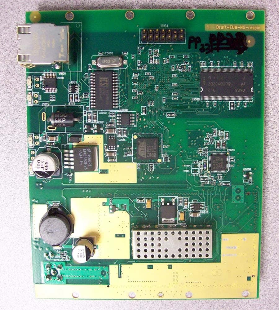
Murandi Communications Ltd. Innovative Radio Frequency Solutions Murandi Communications Ltd. Suite 300, 6715 - 8th St. NE, Calgary, Alberta, Canada, T2E 7H7 Tel: (403) 777-9988email [email protected] Fax: (403) 777-9989www.murandi.com October 14, 2003 Re: Clarification on part number shown on internal photographs. Contained in this directory, are photographs of the circuit card for the EUM3004. Please note that the board revision along the edge of the board calls the board Draft - EUM3003+. The EUM3003+ was renamed to the EUM3004 during development and both represent the same board. Production boards will be called EUM3004.
Internal Photos
Murandi Communications Ltd. Innovative Radio Frequency Solutions Murandi Communications Ltd. Suite 300, 6715 - 8th St. NE, Calgary, Alberta, Canada, T2E 7H7 Tel: (403) 777-9988email [email protected] Fax: (403) 777-9989www.murandi.com October 14, 2003 Re: Clarification on part number shown on internal photographs. Contained in this directory, are photographs of the circuit card for the EUM3004. Please note that the board revision along the edge of the board calls the board Draft - EUM3003+. The EUM3003+ was renamed to the EUM3004 during development and both represent the same board. Production boards will be called EUM3004.
RF Exposure Info
Murandi Communications Ltd. Innovative Radio Frequency Solutions Murandi Communications Ltd. Suite 300, 6715 - 8th St. NE, Calgary, Alberta, Canada, T2E 7H7 Tel: (403) 777-9988email [email protected] Fax: (403) 777-9989www.murandi.com EUM3004 RF Exposure Calculations As per OET Bulliten 65 – Evaluating Compliance with FCC Guidelines for Human Exposure to Radiofrequency Electromagnetic Fields – Edition 97-01, the maximum power density allowed for general population/uncontrolled exposure is f/1500 where f is the frequency of operation in MHz. Calculating for the lowest frequency of operation (905MHz), the maximum power density allowed is 0.603 mW/cm 2 . The power density is calculated as follows: S = (P*G)/(4*pi*R 2 ) where: S = power density in mW/cm 2 P = power at the antenna connector in mW G = linear system gain of the antenna R = separation from antenna (cm) As per the User’s manual, all antennas for the EUM (indoor and outdoor) must be fix-mounted such that there is at least 20cm of separation between the antenna and a person. For an output power of 26dBm (398mW), and a separation of 20cm, the maximum allowable antenna system gain is 8.8dBi. The antenna system gain for all antenna types shown in “EUM3004 Functional Overview” are less than the limit of 8.8dBi, therefore meeting the FCC requirements for human exposure to RF radiation.
Test Report
This report shall not be reproduced, except in full, without prior written approval of MPB Technologies Inc. Test Report Prepared By: Electronics Test Centre 27 East Lake Hill Airdrie, Alberta Canada T4A 2K3 [email protected] http://www.etc-mpb.com/ phone: (403) 912-0037 fax: (403) 912-0083 MPBT Report No.: m01e2860Rev: 1Date: 9 October 2003 Report for Emissions Testing of EUM3004 Wireless Modem In accordance with FCC Part 15, Subpart C (2000) Test Personnel:James MacKay, Jacky Wong, David Raynes Prepared for:WaveRider Communications Inc. 255 Consumers Road Suite 500 Toronto, Ontario Canada M2J 1R4 [email protected] Senior EMC Technologist Electronics Test Centre (Airdrie) Authorized Signatory Test Sample: EUM3004 Wireless Modem FCC Part 15 Subpart C (2000) Report No.:m01e2860 rev. 1 This report shall not be reproduced, except in full, without prior written approval of MPB Technologies Inc. TABLE OF CONTENTS 1.0INTRODUCTION 1.1SCOPE 1.2APPLICANT 1.3APPLICABILITY 1.4TEST SAMPLE DESCRIPTION 1.5GENERAL TEST CONDITIONS AND ASSUMPTIONS 1.6SCOPE OF TESTING 1.6.1 VARIATIONS IN TEST METHODS 1.6.2 EMISSIONS MEASUREMENTS 1.6.3TEST SAMPLE MODIFICATIONS 2.0ABBREVIATIONS 3.0MEASUREMENT UNCERTAINTY 4.0TEST CONCLUSION 4.1 CONDUCTED EMISSIONS AT AC LINES 4.2CONDUCTED EMISSIONS MEASURED AT ANTENNA PORT 4.3 RADIATED EMISSIONS INCLUDING RESTRICTED BANDS OF OPERATION 4.3ARECEIVE MODE 4.3BTRANSMIT MODE 4.3C FIELD STRENGTH OF SPURIOUS RADIATION 5.0TEST FACILITY 5.1 LOCATION 5.2 GROUNDING PLAN 5.3POWER 5.4 EMISSIONS PROFILE 5.5 TEST CONFIGURATION 5.5.1TABLETOP EQUIPMENT 5.5.2RACK MOUNT 6.0TEST EQUIPMENT 6.1 RADIATED EMISSIONS 6.2 CONDUCTED EMISSIONS 6.3 CALIBRATION APPENDIX A:Test Sample Description:EUM3004 Wireless Modem Test Sample: EUM3004 Wireless Modem FCC Part 15 Subpart C (2000) Report No.:m01e2860 rev. 1 This report shall not be reproduced, except in full, without prior written approval of MPB Technologies Inc. 1.0 INTRODUCTION 1.1SCOPE The purpose of this report is to present the findings and results of compliance testing performed in accordance with CFR Title 47 FCC Part 15, Subpart C, Intentional Radiators. 1.2APPLICANT This test report has been prepared for WaveRider Communications Inc., located in Toronto, Ontario, Canada. 1.3APPLICABILITY All test procedures, limits, and results defined in this document apply to the WaveRider Communications Inc. EUM3004 Wireless Modem unit, referred to herein as the Equipment Under Test (EUT). The results contained in this report relate only to the item tested. This report does not imply product endorsement by A2LA, NVLAP or the Canadian or US governments. 1.4TEST SAMPLE DESCRIPTION The test sample provided for testing was an EUM3004 Wireless Modem: Product Type:Wireless modem Model Number:EUM3004 Serial Number:n/a Cables:ethernet, power, RF to antenna Power Requirements: 120 VAC 60 Hz to AC-DC power adapter Peripheral Equipment: Personal Computer More detailed information is provided by WaveRider Communications Inc. in Appendix A. 1.5GENERAL TEST CONDITIONS AND ASSUMPTIONS The EUT was set up and exercised using the configurations, modes of operation and arrangements defined in this report only. All inputs and outputs to and from other equipment associated with the EUT were adequately simulated. Where relevant, the EUT was only tested using the monitoring methods and test criteria defined in this report. Environmental conditions are recorded for each test. Test Sample: EUM3004 Wireless Modem FCC Part 15 Subpart C (2000) Report No.:m01e2860 rev. 1 This report shall not be reproduced, except in full, without prior written approval of MPB Technologies Inc. 1.6SCOPE OF TESTING Testing was performed in accordance with FCC Part 15 Subpart C (2000), and ANSI C63.4 (2000). 1.6.1VARIATIONS IN TEST METHODS There were no variations from the test procedures outlined above. 1.6.2MARGINAL EMISSIONS MEASUREMENTS As noted in Section 4, some emissions were measured to be within -6 dB of the specified limit: 1.6.3TEST SAMPLE CONFIGURATION & MODIFICATIONS The EUM3004 was set up as shown in the photographs. Special test firmware permitted the EUT to be configured to transmit continuously on a selected channel. Configuration commands were issued by a support computer located outside the test chamber. The EUM3004 was positioned on a wooden table in the center of the turntable, when connected to the diversity antenna. This configuration was also used for measuring emissions in the Receive mode of operation. For characterization of all other antennas, the EUM3004 was placed below the turntable groundplane. The EUT met the requirements without modification. 2.0 ABBREVIATIONS AP-Average Peak CE-Conducted Emissions E -Field - Electric Field H-Field - Magnetic Field N/T-Not Tested N/A-Not Applicable PK-Peak QP-Quasi Peak RE-Radiated Emissions 3.0 MEASUREMENT UNCERTAINTY For Radiated E-Field Emissions and Conducted Emissions, the uncertainties in the measurements were calculated using the methods outlined in the NAMAS document, NIS81: May 1984. Frequency= ± 1 kHz Amplitude (RE)= ± 4.01 dB Amplitude (CE)= ± 3.25 dB Test Sample: EUM3004 Wireless Modem FCC Part 15 Subpart C (2000) Report No.:m01e2860 rev. 1 This report shall not be reproduced, except in full, without prior written approval of MPB Technologies Inc. 4.0 TEST CONCLUSION The EUT was subjected to the following tests. Compliance status is reported as PASS or FAIL. Test conditions that are not applicable to the EUT are marked n/a. If testing was not performed at this time, the appropriate field is marked n/t. The following table summarizes the test results in terms of the specification and class or level applied, the unique test sample identification, the EUT modification state, and configuration as applicable. TEST CASE TEST TYPESPECIFICATIONTEST SAMPLE MOD. STATE CONFIGURATIONRESULT §4.1Conducted Emissions at AC lines FCC Part 15.107 and 15.207 EUM3004 Wireless Modem nilSee § 1.6.3 PASS §4.2Conducted Emissions at Antenna…
Text truncated - open the document above for the full version.
Test Setup Photos
Photos of Test Setup For EUM3004 Conducted Emissions at the antenna port Receive Radiated Emissions Receive Radiated Emissions Transmit Radiated Emissions – Diversity antenna Transmit Radiated Emissions – Patch antenna Transmit Radiated Emissions – Panel antenna Transmit Radiated Emissions – Yagi antenna Field Strength of Spurious Data – with Diversity Antenna Please refer to the test report.
Contact Information
Applicant
Lawrence Gordon(Senior Technical Design Lead)
Test Firm
Electronics Test CentreV Mediboina
Technical Specifications
| # | Rule Parts | Frequency Range | Power Output |
|---|---|---|---|
| 1 | 15C | 902 MHz - 928 MHz | 398.00 mW |
Other Applications from Vecima Networks Inc.
OOX-915C
Oct 23, 2007Wireless Transceiver Module
Equipment Class
DTS - Digital Transmission System
OOX-E3K6
May 10, 2006Outdoor Modem
Equipment Class
DTS - Digital Transmission System
OOX-915A
Mar 27, 2006Radio Module
Equipment Class
DTS - Digital Transmission System
OOX-EUM3005
Mar 21, 2005Wireless Modem
Equipment Class
DTS - Digital Transmission System
OOX-EUM3003
Jan 25, 2003Wireless LAN end-user modem
Equipment Class
DTS - Digital Transmission System