OOX-EUM3005Wireless Modem
Vecima Networks Inc.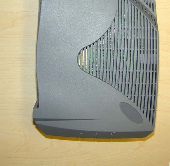
Click to zoom
Application Details
- Equipment Class
- DTS - Digital Transmission System
- Date of Grant
- Mar 21, 2005
- Application Purpose
- Original Equipment
- Date of Application
- Mar 21, 2005
- Equipment Note
- Wireless Modem
- Frequency Range
- 902.00000000 - 928.00000000
- Company
- Vecima Networks Inc.
- Country
- Canada
Documents & Files
Document Text
Text extracted from the exhibit documents filed with the FCC. Open a document above to read the original.
Users Manual
EUM3005 Installation Guide APCD-LM047-1.1 : APCD-LM047-1.1ii Copyright © 2005 by WaveRider Communications Inc. You may copy and/or print as many copies of this manual as you wish, as long as the software license agreement and this copyright statement are included. Release 1.1, March 2005 The following are trademarks or registered trademarks of their respective companies or organi- zations: Windows XP/Microsoft Windows 2000/Microsoft iiiAPCD-LM047-1.1 Software License Agreement This is a legal agreement between you (either an individual or an entity) and WaveRider Communica- tions Inc. for the use of WaveRider computer software, hereinafter the “LICENSED SOFTWARE”. By using the LICENSED SOFTWARE installed in this product, you acknowledge that you have read this license agreement, understand it, and agree to be bound by its terms. You further agree that it is the full and complete agreement between you and WaveRider Communications Inc., superseding all prior written or verbal agreements of any kind related to the LICENSED SOFTWARE. If you do not understand or do not agree to the terms of this agreement, you will cease using the LICENSED SOFTWARE immediately. 1. GRANT OF LICENSE—This License Agreement permits you to use one copy of the LICENSED SOFTWARE. 2. COPYRIGHT—The LICENSED SOFTWARE is owned by WaveRider Communications Inc. and is protected by copyright laws and international treaty provisions; therefore, you must treat the LICENSED SOFTWARE like any other copyrighted material (e.g., a book or magazine). 3. LIMITS OF FEATURE AVAILABILITY—The LICENSED SOFTWARE is sold with limitations as to certain feature availability and use. These limits are governed by the terms of the purchase agreement. Any actions resulting in the exceeding of these limits is not permitted, and can result in unpredictable performance. 4. OTHER RESTRICTIONS—You may not rent or lease the LICENSED SOFTWARE. You may not reverse engineer, decompile, or disassemble the LICENSED SOFTWARE. 5. LIMITED WARRANTY—The LICENSED SOFTWARE is provided “as is” without any warranty of any kind, either expressed or implied, including, but not limited to, the implied warranties of merchantability and fitness for a particular purpose. The entire risk as to the quality and performance of the LICENSED SOFTWARE is with you, the licensee. If the LICENSED SOFTWARE is defective, you assume the risk and liability for the entire cost of all necessary repair, service, or correction. Some states/jurisdictions do not allow the exclusion of implied warranties, so the above exclusion may not apply to you. This warranty gives you specific legal rights, and you may have other rights, which vary from state/jurisdiction to state/ jurisdiction. WaveRider Communications Inc. does not warrant that the functions contained in the LICENSED SOFTWARE will meet your requirements, or that the operation of the LICENSED SOFTWARE will be error-free or uninterrupted. 6. NO OTHER WARRANTIES—To the maximum extent permitted by applicable law, WaveRider Communications Inc. disclaims all other warranties, either express or implied, including, but not limited to, the implied warranties of merchantability and fitness for a particular purpose, with regard to the LICENSED SOFTWARE and the accompanying written materials. 7. NO LIABILITY FOR CONSEQUENTIAL DAMAGES—To the maximum extent permitted by applicable law, in no event shall WaveRider Communications Inc. or its suppliers be liable for any damages whatsoever (including, without limitation, damages for loss of business profits, business interruption, loss of business information, or any other pecuniary loss) arising from the use of or inability to use the LICENSED SOFTWARE, even if WaveRider Communications Inc. has been advised of the possibility of such damages, or for any claim by any other party. Because some states/jurisdictions do not allow the exclusion or limitation of liability for consequential or incidental damages, the above limitation may not apply to you. In no event will WaveRider’s liability exceed the amount paid for the LICENSED SOFTWARE. : APCD-LM047-1.1iv Warranty In the following warranty text, “WaveRider®” shall mean WaveRider Communications Inc. This WaveRider product is warranted against defects in material and workmanship for a period of one (1) year from the date of purchase. During this warranty period WaveRider will, at its option, either repair or replace products that prove to be defective. For warranty service or repair, the product must be returned to a service facility designated by WaveRider. Authorization to return products must be obtained prior to shipment. The WaveR- ider RMA number must be on the shipping documentation so that the service facility will accept the product. The buyer shall pay all shipping charges to WaveRider and WaveRider shall pay shipping charges to return the product to the buyer within Canada or the USA. For all other countries, the buyer shall pay shipping charges as well as duties and taxes incurred in shipping products to or from WaveRider. WaveRider warrants that the firmware designed by it for use with the unit will execute its pro- gramming instructions when properly installed on the unit. WaveRider does not warrant that the operation of the unit or firmware will be uninterrupted or error-free. Limitation of Warranty The foregoing warranty shall not apply to defects resulting from improper or inadequate mainte- nance by the buyer, buyer-supplied interfacing, unauthorized modification or misuse, operation outside the environmental specifications for the product, or improper site preparation or mainte- nance. No other warranty is expressed or implied. WaveRider specifically disclaims the implied warranties of merchantability and fitness for any particular purpose. No Liability for Consequential Damages To the maximum extent permitted by applicable law, in no event shall WaveRider or its suppliers be liable for any damages whatsoever (including, without limita…
Text truncated - open the document above for the full version.
Block Diagram
Murandi Communications Ltd. Innovative Radio Frequency Solutions Murandi Communications Ltd. Suite 300, 6715 - 8th St. NE, Calgary, Alberta, Canada, T2E 7H7 Tel: (403) 777-9988email [email protected] Fax: (403) 777-9989www.murandi.com EUM3005 Block Diagrams The following are the block diagrams for the RF and digital sections of the EUM3005. The blocks shown are as follows: Top level RF section Ethernet PHY Microprocessor/MAC memory Microprocessor/MAC Baseband processor interface 1 Block Diagrams 1.1 Top Level Block Diagram MICRO/MAC MICROPROCESSOR MEMORY (FLASH, SDRAM) BBP 4.2V 2.5V Linear Regulator Ethernet PHY IData+/- OData+/- 2 2 RF Deck Link LED RSSI LED To Antenna 3.3V 3.3V Linear Regulator 3.3V 3.3V JTAG Serial 12 RF 4 AC/DC Adaptor 18 59 15 9 15 TDCLK2 TDO2 TMS2 /TRS2 TDI2 TDCLK1 TDO1 TMS1 /TRS1 TDI1 3.3V GND UTXD URXD 3.3V GND Activity LED Figure 1.1 – Top Level Block Diagram Page 2Printed: 04/06/04 8:51 AM Murandi Communications Ltd. Suite 300, 6715 - 8th St. NE, Calgary, Alberta, Canada, T2E 7H7 Tel: (403) 777-9988Fax: (403) 777-9989 1.2 RF Section 2 3.3V RF M_SCLK_IF_RF M_LE_RF I/Q MOD/DE - MODULATOR 4.2V SYN Front End Filter PA TX RF Image Filter TX Mixer RX Mixer RX RF Image Filter RF LNA PAPE RF LO 975-995 MHz RFSW RXRFAGC TX RX Switch RX IF Amp RXIF- RXIF+ TXIF- TXIF+ XFER 902-928 MHz 70 MHz 902-928 MHz RXIFAGC VREF TXIFAGC RXQ+/- RXI+/- TXI+/- 140 MHz IFLO IFDET TXQ+/- CAL_EN Buffer Legend Shield wall 3.3V LO Regulator 3.3V LO IF Filter TX IF Amp To Antenna XFER M_SD_IF_RF PE1 PE2 M_SD_IF_RF M_SCLK_IF_RF RXRFAGC ANTSEL RFSW M_LE_RF 44MHz REF OSC 44MHz_synth 3.3V Regulator 3.3V RF 44MHz_synth TX Pad ANTSEL Logic 2 70 MHz 3.3V RF 3.3V RF 3.3V LO 4.2V DC 3.3V RF 44MHz Doubler M_LE_IF 2 2 2 To MICRO/MAC To BBP 2 Logic + 2.85V reg RX Pad 4.2V DC Figure 1.2 – RF Section Block Diagram Page 3Printed: 04/06/04 8:51 AM Murandi Communications Ltd. Suite 300, 6715 - 8th St. NE, Calgary, Alberta, Canada, T2E 7H7 Tel: (403) 777-9988Fax: (403) 777-9989 1.3 Digital Section 1.3.1 Ethernet PHY ETHERNET PHY BLOCK ICS ICS1893AF TP_TXP TP_TXN MDIO MDC TP_CT RXD3 TP_RXP RXD2 TP_RXN RXD1 RXD0 RXDV RXCLK RXER REF IN REF OUT TXCLK 10TCSR TXEN TXD0 TXD1 TXD2 TXD3 COL 100TCSR CRS RESET_N P2LI P1CL P3TD P0AC P4RD RESET_ETH TXD0 2 IDATA- ODATA+ ODATA- IDATA+ MDIO RXD3 2 TPA TPB 25MHz 2 k Ω 1% 3.3V MDC RXD2 RXD0 RXD1 RX_DV RX _CLK RX _ER TX _CLK TX _EN TXD1 TXD2 TXD3 COL CRS 1.54 k Ω 1% Pull-downPull-down Pull-down Link LED Pull-up Pull-up 100pF Activity LED 5.3.1 Ethernet PHY Block Diagram Page 4Printed: 04/06/04 8:51 AM Murandi Communications Ltd. Suite 300, 6715 - 8th St. NE, Calgary, Alberta, Canada, T2E 7H7 Tel: (403) 777-9988Fax: (403) 777-9989 1.3.2 Microprocessor/MAC Memory (FLASH,SDRAM) ADDR[10..0] GROUND D ATA[31..0] PROCESSOR MEMORY BLOCK SPI_PCS SPI CLK SPI_MOSI MT48LC2M32B2TG-7 SDRAM AT45DB161B-CNC (16M) FLASH /C S SCK SI SO /RESET /D Q M [3..0] D ATA[31..0] /C AS /R AS /C S0 /W E /C KE /C LK BA1 BA0 D [31..0] A[10..0] SPI_MISO 3.3V 4 Pull-up BA0 BA1 32 11 5.3.2 Microprocessor/MAC Memory Block Diagram Page 5Printed: 04/06/04 8:51 AM Murandi Communications Ltd. Suite 300, 6715 - 8th St. NE, Calgary, Alberta, Canada, T2E 7H7 Tel: (403) 777-9988Fax: (403) 777-9989 1.3.3 Microprocessor/MAC To RF 32 11 RX_DV MDI MDC RSSI LED 3.3V SEL[1] PAPE RADIO_PE RX_PE GPIO[5] TX_PE SYNTH_DATA SYNTH_CLK SEL[0] PAPE UART_RTS GPIO[4] GPIO[2] UART_CTS GPIO[3] GPIO[1] GPIO[0] 4 To Ethernet To Memory 2.5V RXD3 MDO RXD2 RXD1 RXD0 RX_CLK RX _ER TX_CLK TX _EN TXD0 TXD1 TXD2 TXD3 COL CRS RESET _ETH JTAGSerial 4 12 BBTXPE PE1 PE2 CAL _EN RFSW M _SD_IF_RF M_SCLK_IF_RF M_LE_RF M_LE_IF RX_CLK RX _DATA MD_RDY TX _CLK TX _DATA TX _RDY CCA BB _RX_PE BB _TX_PE /RESET BB _CLK BB _DATA R/nW /CS_BBP To BBP Buffer MDIO Reset 3.3V 22MHz MDIO 5.3.3 Microprocessor/MAC Interface Block Diagram Page 6Printed: 04/06/04 8:51 AM Murandi Communications Ltd. Suite 300, 6715 - 8th St. NE, Calgary, Alberta, Canada, T2E 7H7 Tel: (403) 777-9988Fax: (403) 777-9989 1.3.4 BBP Interface BBP BLOCK TO RF IFDET TXI+/- TXQ+/- VREF RXI+/- RXQ+/- TXIFAGC RFIFAGC 2 2 2 2 3.3V 11MHz HFA3861B RX_CLK RX_DATA MD_RDY TX_CLK TX_DATA TX_RDY CCA BB_RX_PE BB_TX_PE /RESET BB_DATA BB_CLK R/nW /CS_BBP To MICRO /MAC ÷ 4 44MHz ÷ 2 22MHz ANTSEL RXRFAGC 5.3.4 BBP Interface Block Diagram
Cover Letter(s)
Murandi Gommunications Ltd. I nnovative Radio F requency So/uilons March 17,2005 Curtis-Straus LLC, 527 Great Road Littleton, MA, USA 01460 Reference: EUM3005 (FCC lD OOX-EUM3005) Request for Confidentiality WaveRider Communications request that the following information regarding the submission of the EUM3005, including its proprietary antenna, be withheld from public inspection, in accordance with CRF 0.457 and 0.459: r Circuit schematics . Bill of materials The reasons for which confidentiality has been requested are: . This product serves a unique and competitive niche in the wireless market. r This information is considered to be proprietary in nature. o This information is considered to be commercially and competitively sensitive. Suite 300, 6715 - 8th St. Tel: (403) 777-9988 Far (403) 777-9989 NE, Calgary, Alberta, Canada, f2E 7H7 emall [email protected] www.murandi.com Murandi Gommunications Ltd.
Cover Letter(s)
Response to TCB Findings 1. Please provide better resolution internal pictures of the board. The components and traces should be clearly visible with proper lighting. Please find updated pictures attached. 2. Please specify the label material. The label material is as follows: 3M #7872 – Thermal transfer matte silver polyester label material 3M #350 – acrylic adhesive 3M #55 – densified Krafc liner 3. Please confirm that new DTS guidelines have been used for antenna conducted port testing. The conducted port testing followed Option 2 Method 1 of the new DTS guidelines for the power spectral density and RMS Output power. 4. Please provide the plots for 6dB BW, RF RMS Power output and PSD tests. For RF RMS Power output plots, see the RF exposure document supplied. Please note that, the plots in that document are all radiated measurements. The table calculates the expected power at the antenna port given the measured EIRP and assuming an antenna gain of 6.2dBi. The results for the actual conducted levels measured at the antenna port are in the test report. The results in the RF exposure are only meant to further support that total EIRP requirements are being met. Please also see additional documents supplied for 6dB BW and PSD. 5. On pages 31 and 36 of the new report, it appears the frequencies above 1GHz have been tested with average detector only. Have peak emissions at those frequencies been checked to satisfy 15.35(b)? Please clarify. Please also supply the spectrum analyzer settings (RBW and VBW) used for QP below 1GHz and average and peak above 1GHz. The peak emissions were all verified by the test house to satisfy 15.35(b); in fact they noted that most of the emissions showed very little difference between average and peak that were of concern. The spectum analyzer settings for the QP testing (below 1 GHz) was done at RBW = 120kHz and a VBW of 3 MHz. The spectrum analyzer settings for the average and peak tests above 1 GHz were done with an RBW = 1MHz and a VBW of 3 MHz.
Cover Letter(s)
Murandi Communications Ltd. Innovative Radio Frequency Solutions Murandi Communications Ltd. Suite 300, 6715 - 8th St. NE, Calgary, Alberta, Canada, T2E 7H7 Tel: (403) 777-9988email [email protected] Fax: (403) 777-9989www.murandi.com April 2, 2004 RE: WaveRider EUM3005 (FCC ID OOX-EUM3005) The manufacturer information of the EUM3005 is as follows: Solectron Winnipeg 1455 Mountain Avenue Winnipeg, Manitoba Canada R2X 2Y9
Internal Photos
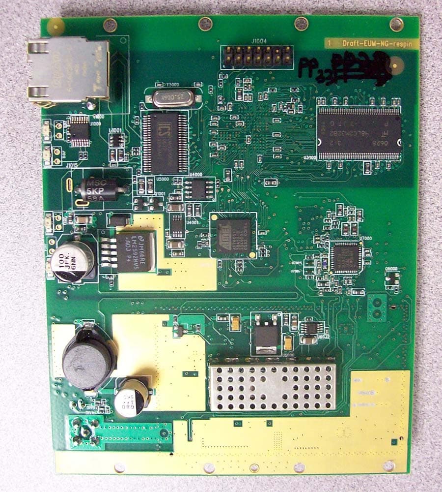
EUM3005 Internal Photographs The following photographs show the circuit card for the EUM3005. Please note that the board revision along the edge of the board calls the board Draft – EUM511. The EUM511 was renamed to the EUM3005 during development and both represent the same board. Production boards will be called EUM3005. EUM3005 bottom view EUM3005 bottom view with shield EUM3005 top view EUM3005 top view with shield
Internal Photos
Murandi Communications Ltd. Innovative Radio Frequency Solutions Murandi Communications Ltd. Suite 300, 6715 - 8th St. NE, Calgary, Alberta, Canada, T2E 7H7 Tel: (403) 777-9988email [email protected] Fax: (403) 777-9989www.murandi.com LMS3000 Diversity Antenna Photos Internal – top view Page 2Printed: 04/06/04 4:20 PM Murandi Communications Ltd. Suite 300, 6715 - 8th St. NE, Calgary, Alberta, Canada, T2E 7H7 Tel: (403) 777-9988Fax: (403) 777-9989 Internal – bottom view Page 3Printed: 04/06/04 4:20 PM Murandi Communications Ltd. Suite 300, 6715 - 8th St. NE, Calgary, Alberta, Canada, T2E 7H7 Tel: (403) 777-9988Fax: (403) 777-9989 External – front view Page 4Printed: 04/06/04 4:20 PM Murandi Communications Ltd. Suite 300, 6715 - 8th St. NE, Calgary, Alberta, Canada, T2E 7H7 Tel: (403) 777-9988Fax: (403) 777-9989 External – rear view Page 5Printed: 04/06/04 4:20 PM Murandi Communications Ltd. Suite 300, 6715 - 8th St. NE, Calgary, Alberta, Canada, T2E 7H7 Tel: (403) 777-9988Fax: (403) 777-9989 External – side view Page 6Printed: 04/06/04 4:20 PM Murandi Communications Ltd. Suite 300, 6715 - 8th St. NE, Calgary, Alberta, Canada, T2E 7H7 Tel: (403) 777-9988Fax: (403) 777-9989 External – unit view
Operational Description
Murandi Communications Ltd. Innovative Radio Frequency Solutions Murandi Communications Ltd. Suite 300, 6715 - 8th St. NE, Calgary, Alberta, Canada, T2E 7H7 Tel: (403) 777-9988email [email protected] Fax: (403) 777-9989www.murandi.com EUM3005 Functional Overview The EUM3005 is a 900MHz radio module intended to provide connectivity between an end-user’s computer and an Internet Service Provider. It is a single PCB wireless solution based on the Intersil PRISM II Direct Sequence Chip Set. The EUM3005 is functionally equivalent to the EUM3004 (previously certified with FCC ID: OOX-EUM3004) in regards to frequency of operation, output power, and modulation scheme. Changes to the microprocessor/MAC controller require that the EUM3005 be re-submitted for certification. Overall functionality The EUM3005 consists of two main sections; the digital and the RF section. Block diagrams for both sections can be found in the document “EUM3005 Block Diagrams”. The digital section contains the following functionality: 1. I/O 2. Ethernet PHY 3. Microprocessor/MAC 4. Memory 5. Power Regulation The radio module’s RF section contains the following functionality: 1. Baseband Processor 2. Modulator/Demodulator (with IF synthesizer) 3. RF Synthesizer 4. Up Converter 5. Power Amplifier 6. Low Noise Amplifier (LNA) 7. Down Converter 8. RF VCO 9. IF VCO 10. Reference Oscillator 11. Antenna (RF) Interface During transmission, data obtained by the Microprocessor from the I/O ports, is transferred to the MAC. The MAC reformats the data and places it on the Baseband Processor TX data line. This data is modulated using CCK modulation and then spread using a defined PN code such that the data is sent at a rate of 2.75Mbit/s. The data is preceded by a header that uses DPSK modulation. Two signals are generated, the In-Phase (I) and Quadrature (Q) components. The I & Q signals are sent to the Modulator/Demodulator where they are first filtered and then modulated with the IF frequency (70 MHz). The IF oscillator generates a 140 MHz signal which is divided by two inside the Modulator/Demodulator and used to modulate the I & Q signals. The final IF signal of 70 MHz is then sent to the Up converter. The Up converter will shift this signal to the RF frequency for the channel programmed in the synthesizer, for operation within the 902-928 MHz ISM band. In the final stage, this signal is amplified to produce +26 dBm RF power output as measured at the output of the antenna port. In receive mode, the radio signal is amplified by the LNA, and then sent to the Down converter. The Down converter converts this signal from the 902-928 MHz range to the IF frequency, 70 MHz. The Page 2Printed: 03/17/05 11:41 AM Murandi Communications Ltd. Suite 300, 6715 - 8th St. NE, Calgary, Alberta, Canada, T2E 7H7 Tel: (403) 777-9988Fax: (403) 777-9989 Modulator/Demodulator then converts the signal to baseband and splits the signal into its I & Q components, before sending it to the Baseband Processor. Finally, the Baseband Processor despreads and demodulates the data contained in the CCK format, and places it on the RX data line to the MAC. The MAC modifies the data, then transfers it to the Microprocessor which reformats the information and sends it out the I/O ports. The RF and IF Local Oscillator signals are generated using the synthesizers and voltage controlled oscillators. The RF synthesizer is programmed with the desired RF channel frequency plus the IF frequency. The IF synthesizer in the Modulator/Demodulator is programmed with 140MHz. The baseband processor and the synthesizer are driven from a common 44 MHz oscillator to control the timing of these chips. Example (for Channel 1 operation): RF IF LO 905 MHz + 70 MHz = 975 MHz Antenna The antenna (RF) connector is a non-standard wide-barrel SMA connector and is connected to a diversity antenna. The unit was qualified with the diversity. For output powers of 26dBm, the antenna system gains shall be 10 dBi or less in order to meet the regulatory requirements of 15.247(b)(4). However, to meet power density requirements of 1.1310, the antenna system gain is limited to 8.8dBi. The following table shows antenna gains for each type of antenna and the associated antenna system gain including cable losses for typical installations. AntennaCableAnt. System #ModelTypeManufacture Gain (dBi) ModelLengthLoss (dB)Gain (dBi) 1WaveRiderDiv Ant.6.2--0.06.2
RF Exposure Info
Murandi Communications Ltd. Innovative Radio Frequency Solutions Murandi Communications Ltd. Suite 300, 6715 - 8th St. NE, Calgary, Alberta, Canada, T2E 7H7 Tel: (403) 777-9988email [email protected] Fax: (403) 777-9989www.murandi.com EUM3005 RF Exposure Calculations As per OET Bulliten 65 – Evaluating Compliance with FCC Guidelines for Human Exposure to Radiofrequency Electromagnetic Fields – Edition 97-01, the maximum power density allowed for general population/uncontrolled exposure is f/1500 where f is the frequency of operation in MHz. Calculating for the lowest frequency of operation (905MHz), the maximum power density allowed is 0.603 mW/cm 2 . The power density is calculated as follows: S = (P*G)/(4*pi*R 2 ) where: S = power density in mW/cm 2 P = power at the antenna connector in mW G = linear system gain of the antenna R = separation from antenna (cm) As per the User’s manual, the antenna for the EUM must be fix-mounted such that there is at least 20cm of separation between the antenna and a person. For an average output power of 25.7dBm (372mW), and a separation of 20cm, the maximum allowable antenna system gain is 9.1dBi. The WaveRider diversity antenna has a maximum gain of 6.2dBi, therefore meeting the FCC requirements for human exposure to RF radiation. The RF exposure limit is further supported based on the following measurements: Page 2Printed: 03/15/05 1:55 PM Murandi Communications Ltd. Suite 300, 6715 - 8th St. NE, Calgary, Alberta, Canada, T2E 7H7 Tel: (403) 777-9988Fax: (403) 777-9989 Page 3Printed: 03/15/05 1:55 PM Murandi Communications Ltd. Suite 300, 6715 - 8th St. NE, Calgary, Alberta, Canada, T2E 7H7 Tel: (403) 777-9988Fax: (403) 777-9989 Page 4Printed: 03/15/05 1:55 PM Murandi Communications Ltd. Suite 300, 6715 - 8th St. NE, Calgary, Alberta, Canada, T2E 7H7 Tel: (403) 777-9988Fax: (403) 777-9989 Page 5Printed: 03/15/05 1:55 PM Murandi Communications Ltd. Suite 300, 6715 - 8th St. NE, Calgary, Alberta, Canada, T2E 7H7 Tel: (403) 777-9988Fax: (403) 777-9989 The power under the curve was integrated in 1MHz bins and correction factors applied to account for cable loss and path loss giving the following EIRP results. Note that the power at the antenna port was calculated from the EIRP measurements assuming an antenna gain of 6.2dB. Fundamental Frequency (MHz) Radiated power Vertical pol. (dBm avg) EIRP Vertical pol. (dBm avg) Radiated power Horizontal pol. (dBm avg) EIRP Horizontal pol. (dBm avg) 90525.231.422.028.2 91525.331.523.429.6 92525.231.420.426.6
Test Report
Murandi Communications Ltd. Innovative Radio Frequency Solutions Murandi Communications Ltd. Suite 300, 6715 - 8th St. NE, Calgary, Alberta, Canada, T2E 7H7 Tel: (403) 777-9988email [email protected] Fax: (403) 777-9989www.murandi.com EUM3005 Additional Information The following three plots show the 6dB emission bandwidth at 905 MHz, 915 MHz and 925 MHz respectively: Page 2Printed: 03/17/05 3:02 PM Murandi Communications Ltd. Suite 300, 6715 - 8th St. NE, Calgary, Alberta, Canada, T2E 7H7 Tel: (403) 777-9988Fax: (403) 777-9989 Page 3Printed: 03/17/05 3:02 PM Murandi Communications Ltd. Suite 300, 6715 - 8th St. NE, Calgary, Alberta, Canada, T2E 7H7 Tel: (403) 777-9988Fax: (403) 777-9989 Page 4Printed: 03/17/05 3:02 PM Murandi Communications Ltd. Suite 300, 6715 - 8th St. NE, Calgary, Alberta, Canada, T2E 7H7 Tel: (403) 777-9988Fax: (403) 777-9989
Test Report
Murandi Communications Ltd. Innovative Radio Frequency Solutions Murandi Communications Ltd. Suite 300, 6715 - 8th St. NE, Calgary, Alberta, Canada, T2E 7H7 Tel: (403) 777-9988email [email protected] Fax: (403) 777-9989www.murandi.com EUM3005 Power Spectral Density The following plots show the power spectral density for the EUM3005 on low, mid and high channels measured using average power measurements as described in option 2 of the new DTS guidelines for the power spectral density and RMS Output power. 905MHz With 21.4dB cable loss, peak power is 6.95dBm Page 2Printed: 03/22/05 12:56 PM Murandi Communications Ltd. Suite 300, 6715 - 8th St. NE, Calgary, Alberta, Canada, T2E 7H7 Tel: (403) 777-9988Fax: (403) 777-9989 915MHz With 21.4dB cable loss, peak power is 6dBm Page 3Printed: 03/22/05 12:56 PM Murandi Communications Ltd. Suite 300, 6715 - 8th St. NE, Calgary, Alberta, Canada, T2E 7H7 Tel: (403) 777-9988Fax: (403) 777-9989 925MHz With 21.4dB cable loss, peak power is 5.9dBm.
Test Report
This report shall not be reproduced, except in full, without prior written approval of MPB Technologies Inc. Page 1 of 46 Test Report Prepared By: Electronics Test Centre 27 East Lake Hill Airdrie, Alberta Canada T4A 2K3 [email protected] http://www.etc-mpb.com/ Telephone: (403) 912-0037 Facsimile: (403) 912-0083 MPBT Report No.: m01e3314 Release 1 Date: 15 March 2005 Emissions Testing of the EUM3005 in accordance with FCC Part 15.247 (2004) Spread Spectrum Operation 902 - 928 & 2400 - 2483.5 & 5725 - 5850 MHz. Test Personnel: Jianming Zhang, David Raynes Prepared for: WaveRider Communications Inc. 255 Consumers Road Suite 500 Toronto, Ontario Canada M2J 1R4 Telephone: 1-403-777-9988 Facsimile: 1-403-777-9889 [email protected] Senior EMC Technologist Electronics Test Centre (Airdrie) Authorized Signatory Test Sample: EUM3005 FCC Part 15.247 (2004) Report Number e12e3158 Release 1 This report shall not be reproduced, except in full, without prior written approval of MPB Technologies Inc. Page 2 of 46 TABLE OF CONTENTS 1.0 INTRODUCTION 1.1 S COPE 1.2 A PPLICANT 1.3 A PPLICABILITY 1.4 T EST SAMPLE DESCRIPTION 1.5 G ENERAL TEST CONDITIONS AND ASSUMPTIONS 1.6 S COPE OF TESTING 1.6.1 VARIATIONS IN TEST METHODS 1.6.2 T EST SAMPLE MODIFICATIONS 2.0 A BBREVIATIONS 3.0 M EASUREMENT UNCERTAINTY 4.0 T EST CONCLUSION 4.1 CONDUCTED EMISSIONS AT AC LINES (PART 15.107 & 15.207) 4.2 C ONDUCTED EMISSIONS MEASURED AT ANTENNA PORT (PART 15.247) 4.3 RADIATED EMISSIONS INCLUDING RESTRICTED BANDS OF OPERATION 4.3 A RECEIVE MODE (PART 15.109) 4.3 B TRANSMIT MODE (PART 2.1053, 15.205, 15.209 & 15.247) 5.0 T EST FACILITY 5.1 LOCATION 5.2 GROUNDING PLAN 5.3 P OWER 5.4 TEST CONFIGURATION 5.5.1 T ABLETOP EQUIPMENT 5.5.2 R ACK MOUNT 6.0 T EST EQUIPMENT 6.1 RADIATED EMISSIONS 6.2 CONDUCTED EMISSIONS 6.3 CALIBRATION APPENDIX A: Test Sample Description: EUM3005 Test Sample: EUM3005 FCC Part 15.247 (2004) Report Number e12e3158 Release 1 This report shall not be reproduced, except in full, without prior written approval of MPB Technologies Inc. Page 3 of 46 1.0 INTRODUCTION 1.1 SCOPE The purpose of this report is to present the findings and results of compliance testing performed in accordance with CFR Title 47 FCC Part 15.247 (2004), Spread Spectrum Operation 902 - 928 & 2400 - 2483.5 & 5725 – 5850 MHz. 1.2 APPLICANT This test report has been prepared for WaveRider Communications Inc., located in Calgary, Alberta, Canada. 1.3 APPLICABILITY All test procedures, limits, and results defined in this document apply to the WaveRider Communications Inc. EUM3005 unit, referred to herein as the Equipment Under Test (EUT). The results contained in this report relate only to the item tested. This report does not imply product endorsement by NVLAP or the Canadian or US governments. 1.4 TEST SAMPLE DESCRIPTION The test sample provided for testing was a EUM3005: Product Type: Wireless Ethernet modem Model Number: EUM3005 Serial Number: N/A Cables: Ethernet – cross cable, power, RF to antenna Power Requirements: 120 VAC 60Hz Peripheral Equipment: IBM laptop, Elpac 3875 power adaptor More detailed information is provided by WaveRider Communications Inc. in Appendix A. 1.5 GENERAL TEST CONDITIONS AND ASSUMPTIONS The EUT was set up and exercised using the configurations, modes of operation and arrangements defined in this report only. All inputs and outputs to and from other equipment associated with the EUT were adequately simulated. Where relevant, the EUT was only tested using the monitoring methods and test criteria defined in this report. Environmental conditions are recorded for each test. Test Sample: EUM3005 FCC Part 15.247 (2004) Report Number e12e3158 Release 1 This report shall not be reproduced, except in full, without prior written approval of MPB Technologies Inc. Page 4 of 46 1.6 SCOPE OF TESTING Testing was performed in accordance with FCC Part 15 Subpart C (2004), and ANSI C63.4 (2004). 1.6.1 V ARIATIONS IN TEST METHODS There were no variations from the test procedures outlined above. 1.6.2 T EST SAMPLE CONFIGURATION & MODIFICATIONS The EUM3005 was set up as shown in the photographs which are submitted separately. The only difference from a normal end-user installation was the Ethernet cable between the EUT and the support computer. This cable was long enough to allow the computer to be located outside the test chamber during Radiated Emission measurements. The EUT met the requirements without modification. 2.0 ACRONYMS AP -Average Peak CE -Conducted Emissions E -Field - Electric Field H -Field - Magnetic Field N/T -Not Tested N/A -Not Applicable PK -Peak QP -Quasi Peak RE -Radiated Emissions 3.0 MEASUREMENT UNCERTAINTY For Radiated E-Field Emissions and Conducted Emissions, the uncertainties in the measurements were calculated using the methods outlined in the NAMAS document, NIS81: May 1984. Frequency = ± 1 kHz Amplitude (RE) = ± 4.01 dB Amplitude (CE) = ± 3.25 dB Test Sample: EUM3005 FCC Part 15.247 (2004) Report Number e12e3158 Release 1 This report shall not be reproduced, except in full, without prior written approval of MPB Technologies Inc. Page 5 of 46 4.0 TEST CONCLUSION STATEMENT OF COMPLIANCE The client equipment referred to in this report was found to comply with the requirements as stated below. The EUT was subjected to the following tests. Compliance status is reported as PASS or FAIL. Test conditions that are not applicable to the EUT are marked n/a. If testing was not performed at this time, the appropriate field is marked n/t. The following table summarizes the test results in terms of the specification and class or level applied, the unique test sample identification, the EUT modification state, and configuration as applicable. TEST CASE TEST TYPE SPECIFICATION TEST SAMPLE MOD. STATE CONFIGURATION RESULT §4.1 Conducted Emissions at AC lines FCC Part 15.107 and 15.207 EUM3005 nil See § 1.6.2 PASS §4.2 Conducted Emiss…
Text truncated - open the document above for the full version.
Contact Information
Applicant
Lawrence Gordon(Senior Technical Design Lead)
Test Firm
Electronics Test CentreV Mediboina
Technical Specifications
| # | Rule Parts | Frequency Range | Power Output |
|---|---|---|---|
| 1 | 15C | 902 MHz - 928 MHz | 342.00 mW |
Other Applications from Vecima Networks Inc.
OOX-915C
Oct 23, 2007Wireless Transceiver Module
Equipment Class
DTS - Digital Transmission System
OOX-E3K6
May 10, 2006Outdoor Modem
Equipment Class
DTS - Digital Transmission System
OOX-915A
Mar 27, 2006Radio Module
Equipment Class
DTS - Digital Transmission System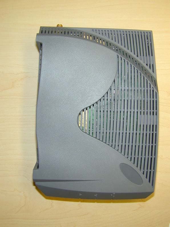
OOX-EUM3004
Nov 10, 2003Wireless LAN end-users modem
Equipment Class
DTS - Digital Transmission System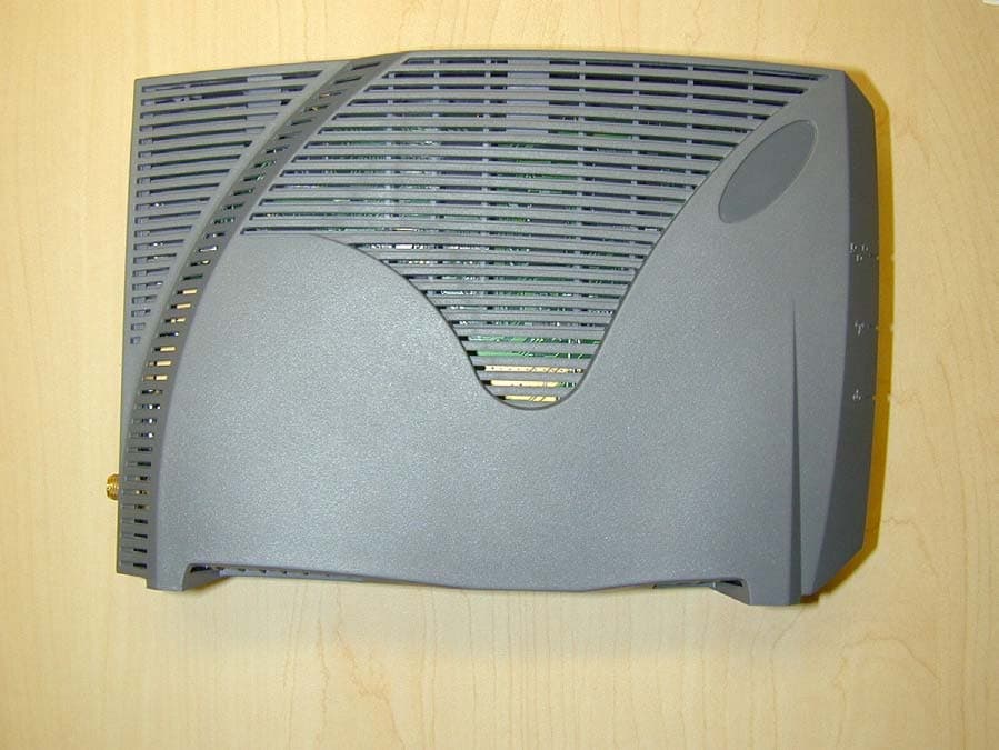
OOX-EUM3003
Jan 25, 2003Wireless LAN end-user modem
Equipment Class
DTS - Digital Transmission System