OOX-NCL1100
Vecima Networks Inc.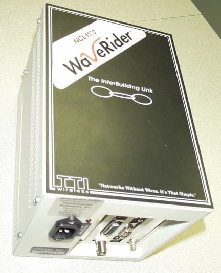
Click to zoom
Application Details
- Equipment Class
- DSS - Part 15 Spread Spectrum Transmitter
- Date of Grant
- Feb 17, 2000
- Application Purpose
- Original Equipment
- Date of Application
- Aug 31, 1999
- Frequency Range
- 2412.00000000 - 2462.00000000
- Company
- Vecima Networks Inc.
- Country
- Canada
Documents & Files
Document Text
Text extracted from the exhibit documents filed with the FCC. Open a document above to read the original.
Users Manual
1990/07/21 NETWORK COMMUNICATIONS LINK 1100 NCL1100 INSTALLATION AND OPERATION MANUAL WaveRider Communications Inc. www.waverider.com NCL1100 Installation & Operation Manual 1990/07/21– 2 – NCL1100 INSTALLATION AND OPERATION MANUAL © 1999 by WaveRider Communications Inc. All rights reserved. This manual may not be reproduced in whole or in part without the express written permission of WaveRider Communications Inc. The information contained in this manual is subject to change without notice. FEDERAL COMMUNICATIONS COMMISSION (USA) This device complies with Part 15 of the FCC rules. Operation of this device is subject to the following conditions: • This device may not cause harmful interference. • This device must accept any interference even if it may cause undesired operation. • The FCC ID of this device is LXX11. WARNING You must install and use this device in strict accordance with the manufacturer’s instructions, and use it only with the manufacturer’s supplied antennae, cables, and other accessories. There is, however, no guarantee that interference from other radio communications will not occur in a particular commercial installation. In the event that these devices do cause harmful interference to an authorized radio service, the user operator must stop operating the devices until the harmful interference is eliminated. WaveRider Communications is not responsible for any radio or television interference caused by improper use of this device, or by the substitution or attachment of connecting cables and equipment other than specified by WaveRider Communications. The correction of interference caused by such improper use is the sole responsibility of the user. NCL1100 Installation & Operation Manual 1990/07/21– 3 – Contents 1INTRODUCTION .................................................................................................................................... 4 1-1Parts List........................................................................................................................................... 4 1-2About the NCL1100 Network Communications Link ........................................................................ 4 2INSTALLATION....................................................................................................................................... 5 2-1Preparation ....................................................................................................................................... 5 2-2NCL1100 Installation ........................................................................................................................ 5 2-3LAN Connection................................................................................................................................ 7 2-4Normal Operating Messages............................................................................................................ 7 2-5Error Messages ................................................................................................................................ 7 3DIAGNOSTICS ....................................................................................................................................... 7 4SNMP INSTALLATION ......................................................................................................................... 11 List of Tables Table 1: pcagent.cfg Fields and Default Values ......................................................................................... 12 List of Figures Figure 1: Potential Obstacles to Line-of-Sight .............................................................................................. 6 Figure 2: Back Panel, Indoor Unit................................................................................................................. 6 Figure 3: Screen, Normal Mode ................................................................................................................... 8 Figure 4: Screen, RF Packets Outgoing....................................................................................................... 9 Figure 5: Display for Local RF Site during Testing ..................................................................................... 10 Figure 6: Display for Remote RF Site during Testing ................................................................................. 10 Figure 7: Display for Local and Remote Sites During Testing ....................................................................11 Figure 8: Spectrum Analyzer Display of Interference ................................................................................. 11 Table of Revisions Revision DateComments July 21, 1999Preliminary user manual release NCL1100 Installation & Operation Manual 1990/07/21– 4 – 1 Introduction This manual explains how to install an NCL1100 Network Communications Link system and operate it in an Ethernet or Token Ring environment, either under IEEE 802.3 or Ethernet II specifications. Ethernet II is not supported at this time for the Token Ring to Ethernet bridge, only Token Ring to IEEE 802.2/802.3 is supported. WaveRider Communications can only provide support for hardware and software that are sold with the NCL1100. WaveRider Communications does not provide support for any third-party equipment. If you purchased an outdoor antenna kit, use its manual for detailed instructions about how to install a directional antenna. 1-1 Parts List The parts included in the NCL1100 package are: • one bridge • one power cord • this manual If any parts are missing, please contact your vendor. 1-2 About the NCL1100 Network Communications Link The NCL1100 Network Communications Link is a platform upon which a LAN transmission system is built. Its basic capabilities include MAC-layer address filtering for traffic management and security. In addition to this, it can use RF techniques to transmit to another site. The NCL1100 configuration you purchased includes the…
Text truncated - open the document above for the full version.
Users Manual
1990/07/21 NETWORK COMMUNICATIONS LINK 1100 NCL1100 INSTALLATION AND OPERATION MANUAL WaveRider Communications Inc. www.waverider.com NCL1100 Installation & Operation Manual 1990/07/21– 2 – NCL1100 INSTALLATION AND OPERATION MANUAL © 1999 by WaveRider Communications Inc. All rights reserved. This manual may not be reproduced in whole or in part without the express written permission of WaveRider Communications Inc. The information contained in this manual is subject to change without notice. FEDERAL COMMUNICATIONS COMMISSION (USA) This device complies with Part 15 of the FCC rules. Operation of this device is subject to the following conditions: • This device may not cause harmful interference. • This device must accept any interference even if it may cause undesired operation. • The FCC ID of this device is LXX11. WARNING You must install and use this device in strict accordance with the manufacturer’s instructions, and use it only with the manufacturer’s supplied antennae, cables, and other accessories. There is, however, no guarantee that interference from other radio communications will not occur in a particular commercial installation. In the event that these devices do cause harmful interference to an authorized radio service, the user operator must stop operating the devices until the harmful interference is eliminated. WaveRider Communications is not responsible for any radio or television interference caused by improper use of this device, or by the substitution or attachment of connecting cables and equipment other than specified by WaveRider Communications. The correction of interference caused by such improper use is the sole responsibility of the user. NCL1100 Installation & Operation Manual 1990/07/21– 3 – Contents 1INTRODUCTION .................................................................................................................................... 4 1-1Parts List........................................................................................................................................... 4 1-2About the NCL1100 Network Communications Link ........................................................................ 4 2INSTALLATION....................................................................................................................................... 5 2-1Preparation ....................................................................................................................................... 5 2-2NCL1100 Installation ........................................................................................................................ 5 2-3LAN Connection................................................................................................................................ 7 2-4Normal Operating Messages............................................................................................................ 7 2-5Error Messages ................................................................................................................................ 8 3DIAGNOSTICS ....................................................................................................................................... 8 4SNMP INSTALLATION ......................................................................................................................... 12 List of Tables Table 1: pcagent.cfg Fields and Default Values ......................................................................................... 12 List of Figures Figure 1: Potential Obstacles to Line-of-Sight .............................................................................................. 6 Figure 2: Back Panel, Indoor Unit................................................................................................................. 6 Figure 3: Screen, Normal Mode ................................................................................................................... 9 Figure 4: Screen, RF Packets Outgoing....................................................................................................... 9 Figure 5: Display for Local RF Site during Testing ..................................................................................... 10 Figure 6: Display for Remote RF Site during Testing ................................................................................. 10 Figure 7: Display for Local and Remote Sites During Testing ....................................................................11 Figure 8: Spectrum Analyzer Display of Interference ................................................................................. 11 Table of Revisions Revision DateComments July 21, 1999Preliminary user manual release NCL1100 Installation & Operation Manual 1990/07/21– 4 – 1 Introduction This manual explains how to install an NCL1100 Network Communications Link system and operate it in an Ethernet or Token Ring environment, either under IEEE 802.3 or Ethernet II specifications. Ethernet II is not supported at this time for the Token Ring to Ethernet bridge, only Token Ring to IEEE 802.2/802.3 is supported. WaveRider Communications can only provide support for hardware and software that are sold with the NCL1100. WaveRider Communications does not provide support for any third-party equipment. If you purchased an outdoor antenna kit, use its manual for detailed instructions about how to install a directional antenna. 1-1 Parts List The parts included in the NCL1100 package are: • one bridge • one power cord • this manual If any parts are missing, please contact your vendor. 1-2 About the NCL1100 Network Communications Link The NCL1100 Network Communications Link is a platform upon which a LAN transmission system is built. Its basic capabilities include MAC-layer address filtering for traffic management and security. In addition to this, it can use RF techniques to transmit to another site. The NCL1100 configuration you purchased includes the…
Text truncated - open the document above for the full version.
Users Manual
1990/07/21 NETWORK COMMUNICATIONS LINK 1100 NCL1100 INSTALLATION AND OPERATION MANUAL WaveRider Communications Inc. www.waverider.com NCL1100 Installation & Operation Manual 1990/07/21– 2 – NCL1100 INSTALLATION AND OPERATION MANUAL © 1999 by WaveRider Communications Inc. All rights reserved. This manual may not be reproduced in whole or in part without the express written permission of WaveRider Communications Inc. The information contained in this manual is subject to change without notice. FEDERAL COMMUNICATIONS COMMISSION (USA) This device complies with Part 15 of the FCC rules. Operation of this device is subject to the following conditions: • This device may not cause harmful interference. • This device must accept any interference even if it may cause undesired operation. • The FCC ID of this device is LXX11. WARNING You must install and use this device in strict accordance with the manufacturer’s instructions, and use it only with the manufacturer’s supplied antennae, cables, and other accessories. There is, however, no guarantee that interference from other radio communications will not occur in a particular commercial installation. In the event that these devices do cause harmful interference to an authorized radio service, the user operator must stop operating the devices until the harmful interference is eliminated. WaveRider Communications is not responsible for any radio or television interference caused by improper use of this device, or by the substitution or attachment of connecting cables and equipment other than specified by WaveRider Communications. The correction of interference caused by such improper use is the sole responsibility of the user. NCL1100 Installation & Operation Manual 1990/07/21– 3 – Contents 1INTRODUCTION .................................................................................................................................... 4 1-1Parts List........................................................................................................................................... 4 1-2About the NCL1100 Network Communications Link ........................................................................ 4 2INSTALLATION....................................................................................................................................... 5 2-1Preparation ....................................................................................................................................... 5 2-2NCL1100 Installation ........................................................................................................................ 5 2-3LAN Connection................................................................................................................................ 7 2-4Normal Operating Messages............................................................................................................ 7 2-5Error Messages ................................................................................................................................ 8 3DIAGNOSTICS ....................................................................................................................................... 8 4SNMP INSTALLATION ......................................................................................................................... 12 List of Tables Table 1: pcagent.cfg Fields and Default Values ......................................................................................... 12 List of Figures Figure 1: Potential Obstacles to Line-of-Sight .............................................................................................. 6 Figure 2: Back Panel, Indoor Unit................................................................................................................. 6 Figure 3: Screen, Normal Mode ................................................................................................................... 9 Figure 4: Screen, RF Packets Outgoing....................................................................................................... 9 Figure 5: Display for Local RF Site during Testing ..................................................................................... 10 Figure 6: Display for Remote RF Site during Testing ................................................................................. 10 Figure 7: Display for Local and Remote Sites During Testing ....................................................................11 Figure 8: Spectrum Analyzer Display of Interference ................................................................................. 11 Table of Revisions Revision DateComments July 21, 1999Preliminary user manual release NCL1100 Installation & Operation Manual 1990/07/21– 4 – 1 Introduction This manual explains how to install an NCL1100 Network Communications Link system and operate it in an Ethernet or Token Ring environment, either under IEEE 802.3 or Ethernet II specifications. Ethernet II is not supported at this time for the Token Ring to Ethernet bridge, only Token Ring to IEEE 802.2/802.3 is supported. WaveRider Communications can only provide support for hardware and software that are sold with the NCL1100. WaveRider Communications does not provide support for any third-party equipment. If you purchased an outdoor antenna kit, use its manual for detailed instructions about how to install a directional antenna. 1-1 Parts List The parts included in the NCL1100 package are: • one bridge • one power cord • this manual If any parts are missing, please contact your vendor. 1-2 About the NCL1100 Network Communications Link The NCL1100 Network Communications Link is a platform upon which a LAN transmission system is built. Its basic capabilities include MAC-layer address filtering for traffic management and security. In addition to this, it can use RF techniques to transmit to another site. The NCL1100 configuration you purchased includes the…
Text truncated - open the document above for the full version.
Attestation Statements
WaveRider Communications (Canada) Inc. 6120 - 1A Street SW, Calgary, Alberta T2G 0G3 Tel: 403•319•2350 Fax: 403•319•2359 web: www.waverider.com FCC AUTHORIZATION Date: 1 September, 1999 Time: 08:00 To:FCC Authorization & Evaluation Division 7435 Oakland Mills Road Columbia, MD 21045-0429 From:J. Ivan Rodrigues Telephone:(403) 319-2350 Senior Radio Systems Manager FAX:(403) 319-2359 e-mail:[email protected] Applicant:WaveRider Communications Inc. 6120 – 1A Street S.W. Calgary, Alberta CANADA T2H 0G3 Dear Ladies and/or Gentlemen: I appoint Kenneth L. Boston and James Blaha at L.S. Compliance, Inc., to act as an agent in the preparation under Part 15 of the rules and regulations of the Federal Communications Commission. I certify that the exhibitions properly describe the device being submitted under this application and will implement any changes described in the test report. The labels described will be affixed to each item. The following statement is required by the Federal Communications Commission: By checking Yes, the applicant certifies that, in the case of an individual applicant, he or she is not subject to a denial of federal benefits, that included FCC benefits, pursuant to section 5301 of the Anti-Drug Abuse Act of 1988, 21 U.S.C. 853(a), or, in the case of a non-individual applicant (e.g. corporation, partnership, or other unincorporated association), no party to the application is subject to a denial of federal benefits, that includes FCC benefits, pursuant to that section. __X__ YES_____ NO Dated this __1st__ day of September, 1999. By: ______________________________ J. Ivan Rodrigues Title: Senior Radio Systems Manager, WaveRider Communications Inc. Phone: (403) 319-2350
Attestation Statements
WaveRider Communications (Canada) Inc. 6120 - 1A Street SW, Calgary, Alberta T2G 0G3 Tel: 403•319•2350 Fax: 403•319•2359 web: www.waverider.com Addendum to the Theory of Operation 1. Theoretical Processing Gain: PG(theor.) = 10log(chip rate / data rate) + 10log(2 x bits/symbol) = 10log(11 Mcps/11 Mbps) + 10log(2 x 8 bits/symbol) = 12.04 dB 2. Data Rate: The NCL1100 is configured and intended for raw data transmission rates of 11 Mbps. 3. Chip-Symbol Ratio: There are 8 bits conveyed per symbol, for each the I and Q channels, using Quadrature M-ary Bi-Orthogonal Keying (QMBOK) modulation. 4. Spread Rate: The spread rate implemented is 11 Mcps. Ivan Rodrigues WaveRider, Inc.
Attestation Statements
RESPONSE TO ITEMS REQUESTED BY FCC - OET Correspondence #: 11209 on 28 December, 1999: Re: FCC ID OOX-NCL1100 Applicant: Waverider Communications ( Canada ), Inc. Correspondence Reference Number: 11209 731 Confirmation Number: EA95321 Date of Original E-Mail: 12/28/1999 1) Please submit information requested in item # 4 of the 10/27/1999 fax. *** The process gain measurements must be submitted at the highest data rate for each Chip/symbol rate. 2) When measuring the output power, the RBW must be greater than the 6 dB bandwidth and the VBW must be greater than the RBW. The 6 dB bandwidth of the device is about 12 MHz wide. Retest with the proper analyzer settings or use a power meter. 3) List all antennas, the antenna gain, the output power and total EIRP( Power in dBm + Antenna gain in dBi) for each. 4) The submitted RF exhibit is under review and will be forwarded as soon as possible. The items indicated above must be submitted before processing can continue on the above referenced application. Failure to provide the requested information within 60 days of the original e-mail date may result in application dismissal pursuant to Section 2.917 (c) and forfeiture of the filing fee pursuant to section 1.1108. Responses to these four items are found on the following pages. RESPONSE TO #1... The Waverider model NCL-1100 module runs only at a data rate of 11 MBS, and a chip to symbol ratio of 8:1, this was the only rate used, and reflects the system parameters in use for the jamming margin test submitted with the filing. This test was performed on a Product using the Harris Chipset, at the same designated rates, and the results were submitted with this product filing, as per the e-mail from Greg Chumack, referenced in the Technical Report. RESPONSE TO #2... From the original test report, Power output recorded on 31 August, 1999: 2.6 Power Output Test Performed For the 15.247b measurement, the output of the Waverider model NCL 1100 module, including bandpass filter and lightning arrestor, was connected via a short jumper cable created only for this measurement, into the input of the HP E4407B Spectrum Analyzer. The unit was configured to run in a continuous transmit mode, with a pseudo-random test code supplied by software to provide modulation. The HP receiver was set to a 5 MHz Bandwidth, and the transmitted signal was then stored, with the peak signal level stored. This power level was collected for the lowest, highest and middle channels and can be seen in the chart presented below. CHANNEL CENTER FREQ (MHz) LIMIT (dBm) MEASURED POWER (dBm) MARGIN (dB) 1241230 dBm15.1714.83 3243230 dBm15.6614.34 6246230 dBm17.0013.00 From a retest performed on 24 January,2000, using a calorimetric power meter: Power output measured with Gigatronics 8542C power meter (with 80301A Shottky diode sensor head), and compared to the power read with the HP E4407B Spectrum analyzer in a 5 MHz bandwidth. The sample tested at this time was a different sample than the one tested previously; this sample has a serial number of 015717. CHANNELFREQUENCY (MHz) LIMIT (dBm) POWER ANALYZER MARGIN (dB) POWER METER MARGIN 1241230 dBm15.414.614.915.1 2242230 dBm15.614.415.514.5 3243230 dBm15.814.215.914.1 4244230 dBm16.213.816.313.7 5245230 dBm15.914.116.014.0 6246230 dBm15.214.815.314.7 RESPONSE TO #3... The Waverider wireless bridge is an exclusive fixed, point to point system, that uses a 24 dBi gain parabola mounted on a pipe or tower in a fixed outdoor application. Below is the specifications for the Conifer 26T-2400. At the bottom of the specification sheet is a set of calculations detailing the system radiated power output parameters. Only the Conifer 26T-2400 antenna is supplied with the system: Pout + Gain:17 DBm + 24 dB = 41 dBm (eirp) Pout of 17 dBm measured maximum. Antenna gain of 24 dBi quoted gain. For this antenna, 15.247(b)(3)(i) allows: Pout + Gain < 48 dBm (eirp) 30 dBm {1 watt allowed by 15.247 (b)(1)} less { (24-6) / 3 } or 6 dB = 24 dBm so 24 dBm (allowed power) + 24 dB (antenna gain) = 48 dBm (eirp) RESPONSE TO #4... This response has been created separately, and submitted into the RF safety folder. Kenneth Boston EMC Lab Manager L. S. Compliance, Inc.
Attestation Statements
RESPONSE TO ITEMS REQUESTED BY FCC - OET Correspondence #: 11209 on 28 December, 1999: Re: FCC ID OOX-NCL1100 Applicant: Waverider Communications ( Canada ), Inc. Correspondence Reference Number: 11209 731 Confirmation Number: EA95321 Date of Original E-Mail: 12/28/1999 1) Please submit information requested in item # 4 of the 10/27/1999 fax. *** The process gain measurements must be submitted at the highest data rate for each Chip/symbol rate. 2) When measuring the output power, the RBW must be greater than the 6 dB bandwidth and the VBW must be greater than the RBW. The 6 dB bandwidth of the device is about 12 MHz wide. Retest with the proper analyzer settings or use a power meter. 3) List all antennas, the antenna gain, the output power and total EIRP( Power in dBm + Antenna gain in dBi) for each. 4) The submitted RF exhibit is under review and will be forwarded as soon as possible. The items indicated above must be submitted before processing can continue on the above referenced application. Failure to provide the requested information within 60 days of the original e-mail date may result in application dismissal pursuant to Section 2.917 (c) and forfeiture of the filing fee pursuant to section 1.1108. Responses to these four items are found on the following pages. RESPONSE TO #1... The Waverider model NCL-1100 module runs only at a data rate of 11 MBS, and a chip to symbol ratio of 8:1, this was the only rate used, and reflects the system parameters in use for the jamming margin test submitted with the filing. This test was performed on a Product using the Harris Chipset, at the same designated rates, and the results were submitted with this product filing, as per the e-mail from Greg Chumack, referenced in the Technical Report. RESPONSE TO #2... From the original test report, Power output recorded on 31 August, 1999: 2.6 Power Output Test Performed For the 15.247b measurement, the output of the Waverider model NCL 1100 module, including bandpass filter and lightning arrestor, was connected via a short jumper cable created only for this measurement, into the input of the HP E4407B Spectrum Analyzer. The unit was configured to run in a continuous transmit mode, with a pseudo-random test code supplied by software to provide modulation. The HP receiver was set to a 5 MHz Bandwidth, and the transmitted signal was then stored, with the peak signal level stored. This power level was collected for the lowest, highest and middle channels and can be seen in the chart presented below. CHANNEL CENTER FREQ (MHz) LIMIT (dBm) MEASURED POWER (dBm) MARGIN (dB) 1241230 dBm15.1714.83 3243230 dBm15.6614.34 6246230 dBm17.0013.00 From a retest performed on 24 January,2000, using a calorimetric power meter: Power output measured with Gigatronics 8542C power meter (with 80301A Shottky diode sensor head), and compared to the power read with the HP E4407B Spectrum analyzer in a 5 MHz bandwidth. The sample tested at this time was a different sample than the one tested previously; this sample has a serial number of 015717. CHANNELFREQUENCY (MHz) LIMIT (dBm) POWER ANALYZER MARGIN (dB) POWER METER MARGIN 1241230 dBm15.414.614.915.1 2242230 dBm15.614.415.514.5 3243230 dBm15.814.215.914.1 4244230 dBm16.213.816.313.7 5245230 dBm15.914.116.014.0 6246230 dBm15.214.815.314.7 RESPONSE TO #3... The Waverider wireless bridge is an exclusive fixed, point to point system, that uses a 24 dBi gain parabola mounted on a pipe or tower in a fixed outdoor application. Below is the specifications for the Conifer 26T-2400. At the bottom of the specification sheet is a set of calculations detailing the system radiated power output parameters. Only the Conifer 26T-2400 antenna is supplied with the system: Pout + Gain:17 DBm + 24 dB = 41 dBm (eirp) Pout of 17 dBm measured maximum. Antenna gain of 24 dBi quoted gain. For this antenna, 15.247(b)(3)(i) allows: Pout + Gain < 48 dBm (eirp) 30 dBm {1 watt allowed by 15.247 (b)(1)} less { (24-6) / 3 } or 6 dB = 24 dBm so 24 dBm (allowed power) + 24 dB (antenna gain) = 48 dBm (eirp) RESPONSE TO #4... This response has been created separately, and submitted into the RF safety folder. Kenneth Boston EMC Lab Manager L. S. Compliance, Inc.
Attestation Statements
. . . . . . . . . . L. S. Compliance, Inc. MEMO Date: January 31, 2000 To:FCC Attention: Mr. Joe Dichoso From:L. S. Compliance, Inc. Jim Blaha Subject: EA 95321 FCC ID #: OOX-NCL1100 Change request to Form 731 Dear Joe, I am submitting this memo to request a change to the original FCC Form 731 filing I submitted. On the original Form 731, item 12 had the Rated RF Output Power to be .032 watts. I request the filing to be changed to read... .050 Rated RF Output Power. I apologize for the need to have a change request. Jim Blaha L. S. Compliance, Inc. W66 N220 Commerce Court Cedarburg, Wisconsin 53012 Phone: 414 - 375 - 4400 Fax: 414 - 375 - 4248
Attestation Statements
L. S. COMPLIANCE, Inc. Date: January 31, 2000 To:FCC Attention: Mr. Joe Dichoso From:L. S. Compliance, Inc. Jim Blaha Subject:EA 95321 FCC ID #: OOX-NCL1100 Change request to Form 731 Dear Joe, I am submitting this memo to request a change to the original FCC Form 731 filing I submitted. On the original Form 731, item 12 had the Rated RF Output Power to be .032 watts. I request the filing to be changed to read... .050 Rated RF Output Power. I apologize for the need to have a change request. Jim Blaha
Cover Letter(s)
WaveRider Communications …
Text truncated - open the document above for the full version.
Contact Information
Applicant
Lawrence Gordon(Senior Technical Design Lead)
Technical Contact
Waverider Communications, Inc.Ivan Rodrigues
[email protected]403-319-2350
6120 1A Street S.W. · Calgary, Alberta · Canada
Non-Technical Contact
L. S. Compliance, Inc.James Blaha
[email protected]414-375-4400
Test Firm
L. S. Compliance, Inc.James Blaha
262-375-4400Fax: 262-375-4248
Technical Specifications
| # | Rule Parts | Frequency Range | Power Output |
|---|---|---|---|
| 1 | 15C | 2.41 GHz - 2.46 GHz | 50.00 mW |
Other Applications from Vecima Networks Inc.
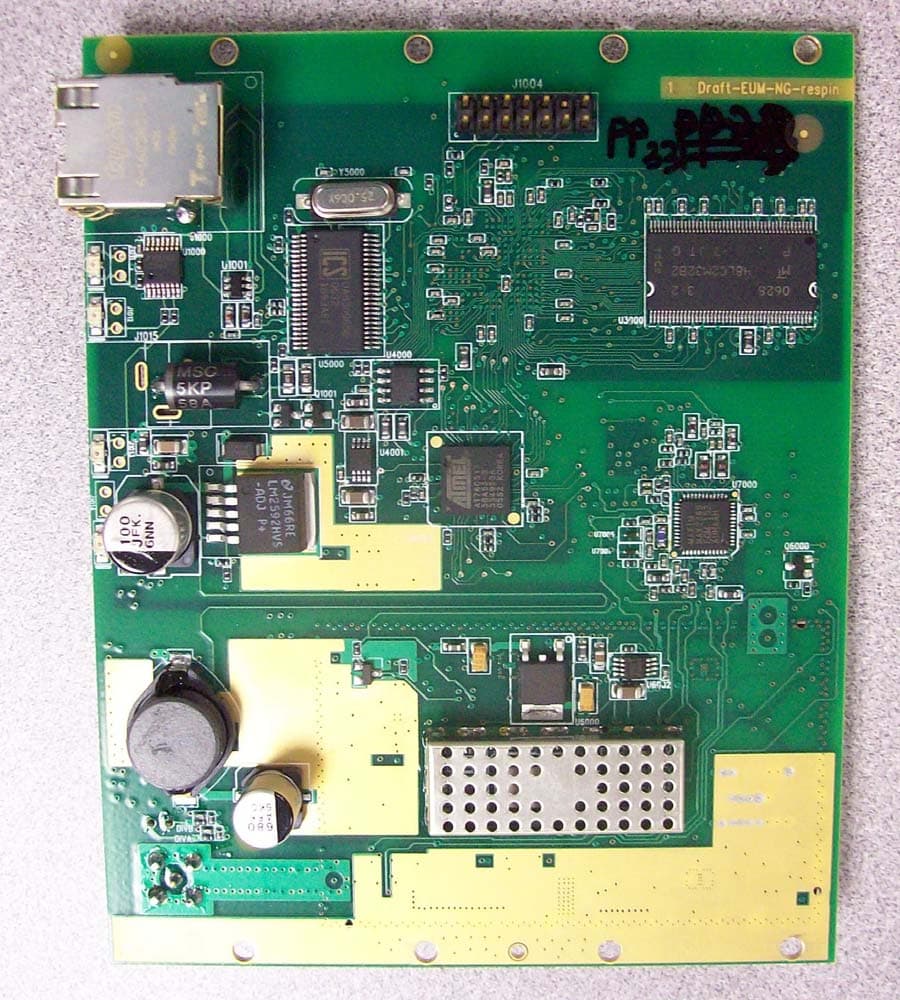
OOX-915C
Oct 23, 2007Wireless Transceiver Module
Equipment Class
DTS - Digital Transmission System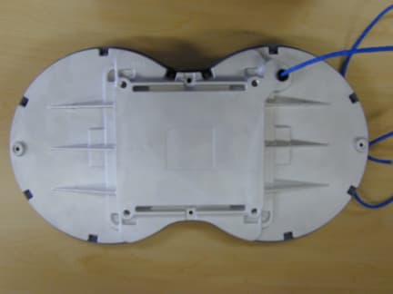
OOX-E3K6
May 10, 2006Outdoor Modem
Equipment Class
DTS - Digital Transmission System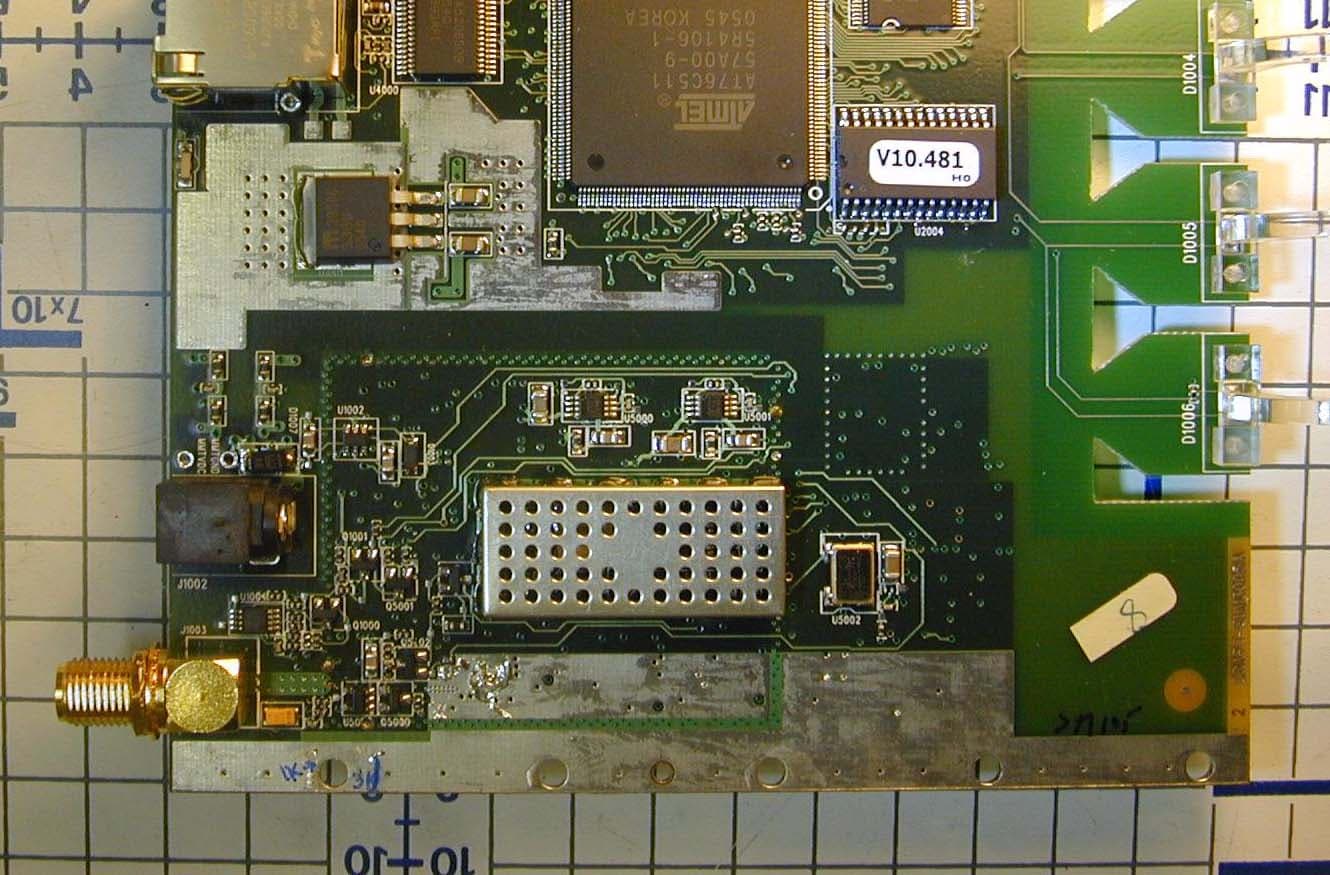
OOX-915A
Mar 27, 2006Radio Module
Equipment Class
DTS - Digital Transmission System
OOX-EUM3005
Mar 21, 2005Wireless Modem
Equipment Class
DTS - Digital Transmission System
OOX-EUM3004
Nov 10, 2003Wireless LAN end-users modem
Equipment Class
DTS - Digital Transmission System