OOX-WRM11512.4GHz 6 Channel DSSS Transceiver
Vecima Networks Inc.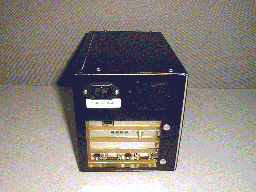
Click to zoom
Application Details
- Equipment Class
- DSS - Part 15 Spread Spectrum Transmitter
- Date of Grant
- Aug 24, 2000
- Application Purpose
- Original Equipment
- Date of Application
- Aug 24, 2000
- Equipment Note
- 2.4GHz 6 Channel DSSS Transceiver
- Frequency Range
- 2412.00000000 - 2462.00000000
- Company
- Vecima Networks Inc.
- Country
- Canada
Documents & Files
Document Text
Text extracted from the exhibit documents filed with the FCC. Open a document above to read the original.
Users Manual
NCL1135 User Manual Version 2.0 WaveRider Communications Inc. Software License Agreement This is a legal agreement between you (either an individual or an entity) and WaveRider Communications Inc. for the use of WaveRider computer software, hereinafter the “LICENSED SOFTWARE”. By using the LICENSED SOFTWARE installed in this product, you acknowledge that you have read this license agreement, understand it, and agree to be bound by its terms. You further agree that it is the full and complete agreement between you and WaveRider Communications Inc., superseding all prior written or verbal agreements of any kind related to the LICENSED SOFTWARE. If you do not understand or do not agree to the terms of this agreement, you must cease using the LICENSED SOFTWARE immediately. 1GRANT OF LICENSE—This License Agreement permits you to use one copy of the LICENSED SOFTWARE. 2.COPYRIGHT—The LICENSED SOFTWARE is owned by WaveRider Communications Inc. and is protected by copyright laws and international treaty provisions; therefore, you must treat the LICENSED SOFTWARE like any other copyrighted material (e.g., a book or magazine). You may not copy the written materials accompanying the LICENSED SOFTWARE. 3.OTHER RESTRICTIONS—You may not rent or lease the LICENSED SOFTWARE. You may not reverse engineer, decompile, or disassemble the LICENSED SOFTWARE. 4.LIMITED WARRANTY—The LICENSED SOFTWARE is provided “as is” without any warranty of any kind, either expressed or implied, including, but not limited to, the implied warranties of merchantability and fitness for a particular purpose. The entire risk as to the quality and performance of the LICENSED SOFTWARE is with you, the licensee. If the LICENSED SOFTWARE is defective, you assume the risk and liability for the entire cost of all necessary repair, service, or correction. Some states/jurisdictions do not allow the exclusion of implied warranties, so the above exclusion may not apply to you. This warranty gives you specific legal rights, and you may have other rights, which vary from state/jurisdiction to state/jurisdiction. WaveRider Communications Inc. does not warrant that the functions contained in the LICENSED SOFTWARE will meet your requirements, or that the operation of the LICENSED SOFTWARE will be error-free or uninterrupted. 5.NO OTHER WARRANTIES—To the maximum extent permitted by applicable law, WaveRider Communications Inc. disclaims all other warranties, either express or implied, including, but not limited to, the implied warranties of merchantability and fitness for a particular purpose, with regard to the LICENSED SOFTWARE and the accompanying written materials. 6.NO LIABILITY FOR CONSEQUENTIAL DAMAGES—To the maximum extent permitted by applicable law, in no event shall WaveRider Communications Inc. or its suppliers be liable for any damages whatsoever (including, without limitation, damages for loss of business profits, business interruption, loss of business information, or any other pecuniary loss) arising from the use of or inability to use the LICENSED SOFTWARE, even if WaveRider Communications Inc. has been advised of the possibility of such damages, or for any claim by any other party. Because some states/jurisdictions do not allow the exclusion or limitation of liability for consequential or incidental damages, the above limitation may not apply to you. In no event will WaveRider’s liability exceed the amount paid for the LICENSED SOFTWARE. The following are trademarks or registered trademarks of their respective companies or organizations: Microsoft Internet Explorer/Microsoft Corporation Netscape/Netscape Communications Corporation © 2000 by WaveRider Communications Inc. All rights reserved. This manual may not be reproduced by any means in whole or in part without the express written permission of WaveRider Communications Canada Inc. Version 2.0, July 2000 Warranty In the following warranty text, “WaveRider®” shall mean WaveRider Communications Inc. This WaveRider product is warranted against defects in material and workmanship for a period of one (1) year from the date of purchase. This limited warranty extends only to the original purchaser. During this warranty period WaveRider will, at its option, either repair or replace products that prove to be defective. For warranty service or repair, the product must be returned to a service facility designated by WaveRider. Authorization to return products must be obtained prior to shipment. The WaveRider RMA number must be on the shipping documentation so that the service facility will accept the product. The buyer shall pay all shipping charges to WaveRider and WaveRider shall pay shipping charges to return the product to the buyer within Canada or the USA. For all other countries, the buyer shall pay shipping charges as well as duties and taxes incurred in shipping products to or from WaveRider. WaveRider warrants that the firmware designed by it for use with the unit will execute its programming instructions when properly installed on the unit. WaveRider does not warrant that the operation of the unit or firmware will be uninterrupted or error-free. Limitation of Warranty The foregoing warranty shall not apply to defects resulting from improper or inadequate maintenance by the buyer, buyer-supplied interfacing, unauthorized modification or misuse, operation outside the environmental specifications for the product, or improper site preparation or maintenance or exposure to abnormal physical or electrical stress or accident. No other warranty is expressed or implied. WaveRider specifically disclaims the implied warranties of merchantability and fitness for any particular purpose. No Liability for Consequential Damages To the maximum extent permitted by applicable law, in no event shall WaveRider or its suppliers be liable for any damages whatsoever (including, without limitation, damages for loss of business profits, business interruption, loss of business information, or any other…
Text truncated - open the document above for the full version.
Users Manual
NCL1135 User Manual Version 1.0 WaveRider Communications Inc. Software License Agreement This is a legal agreement between you (either an individual or an entity) and WaveRider Communications Inc. for the use of WaveRider computer software, hereinafter the “LICENSED SOFTWARE”. By using the LICENSED SOFTWARE installed in this product, you acknowledge that you have read this license agreement, understand it, and agree to be bound by its terms. You further agree that it is the full and complete agreement between you and WaveRider Communications Inc., superseding all prior written or verbal agreements of any kind related to the LICENSED SOFTWARE. If you do not understand or do not agree to the terms of this agreement, you must cease using the LICENSED SOFTWARE immediately. 1GRANT OF LICENSE—This License Agreement permits you to use one copy of the LICENSED SOFTWARE. 2.COPYRIGHT—The LICENSED SOFTWARE is owned by WaveRider Communications Inc. and is protected by copyright laws and international treaty provisions; therefore, you must treat the LICENSED SOFTWARE like any other copyrighted material (e.g., a book or magazine). You may not copy the written materials accompanying the LICENSED SOFTWARE. 3.OTHER RESTRICTIONS—You may not rent or lease the LICENSED SOFTWARE. You may not reverse engineer, decompile, or disassemble the LICENSED SOFTWARE. 4.LIMITED WARRANTY—The LICENSED SOFTWARE is provided “as is” without any warranty of any kind, either expressed or implied, including, but not limited to, the implied warranties of merchantability and fitness for a particular purpose. The entire risk as to the quality and performance of the LICENSED SOFTWARE is with you, the licensee. If the LICENSED SOFTWARE is defective, you assume the risk and liability for the entire cost of all necessary repair, service, or correction. Some states/jurisdictions do not allow the exclusion of implied warranties, so the above exclusion may not apply to you. This warranty gives you specific legal rights, and you may have other rights, which vary from state/jurisdiction to state/jurisdiction. WaveRider Communications Inc. does not warrant that the functions contained in the LICENSED SOFTWARE will meet your requirements, or that the operation of the LICENSED SOFTWARE will be error-free or uninterrupted. 5.NO OTHER WARRANTIES—To the maximum extent permitted by applicable law, WaveRider Communications Inc. disclaims all other warranties, either express or implied, including, but not limited to, the implied warranties of merchantability and fitness for a particular purpose, with regard to the LICENSED SOFTWARE and the accompanying written materials. 6.NO LIABILITY FOR CONSEQUENTIAL DAMAGES—To the maximum extent permitted by applicable law, in no event shall WaveRider Communications Inc. or its suppliers be liable for any damages whatsoever (including, without limitation, damages for loss of business profits, business interruption, loss of business information, or any other pecuniary loss) arising from the use of or inability to use the LICENSED SOFTWARE, even if WaveRider Communications Inc. has been advised of the possibility of such damages, or for any claim by any other party. Because some states/jurisdictions do not allow the exclusion or limitation of liability for consequential or incidental damages, the above limitation may not apply to you. In no event will WaveRider’s liability exceed the amount paid for the LICENSED SOFTWARE. The following are trademarks or registered trademarks of their respective companies or organizations: Microsoft Internet Explorer/Microsoft Corporation Netscape/Netscape Communications Corporation © 2000 by WaveRider Communications Inc. All rights reserved. This manual may not be reproduced by any means in whole or in part without the express written permission of WaveRider Communications Canada Inc. Version 1.0, July 2000 Warranty In the following warranty text, “WaveRider®” shall mean WaveRider Communications Inc. This WaveRider product is warranted against defects in material and workmanship for a period of one (1) year from the date of purchase. This limited warranty extends only to the original purchaser. During this warranty period WaveRider will, at its option, either repair or replace products that prove to be defective. For warranty service or repair, the product must be returned to a service facility designated by WaveRider. Authorization to return products must be obtained prior to shipment. The WaveRider RMA number must be on the shipping documentation so that the service facility will accept the product. The buyer shall pay all shipping charges to WaveRider and WaveRider shall pay shipping charges to return the product to the buyer within Canada or the USA. For all other countries, the buyer shall pay shipping charges as well as duties and taxes incurred in shipping products to or from WaveRider. WaveRider warrants that the firmware designed by it for use with the unit will execute its programming instructions when properly installed on the unit. WaveRider does not warrant that the operation of the unit or firmware will be uninterrupted or error-free. Limitation of Warranty The foregoing warranty shall not apply to defects resulting from improper or inadequate maintenance by the buyer, buyer-supplied interfacing, unauthorized modification or misuse, operation outside the environmental specifications for the product, or improper site preparation or maintenance or exposure to abnormal physical or electrical stress or accident. No other warranty is expressed or implied. WaveRider specifically disclaims the implied warranties of merchantability and fitness for any particular purpose. No Liability for Consequential Damages To the maximum extent permitted by applicable law, in no event shall WaveRider or its suppliers be liable for any damages whatsoever (including, without limitation, damages for loss of business profits, business interruption, loss of business information, or any other…
Text truncated - open the document above for the full version.
Cover Letter(s)
WaveRider Communications (Canada) Inc. 6120 - 1A Street SW, Calgary, Alberta T2H 0G3 Tel: 403•319•2350 Fax: 403•319•2359 web: www.waverider.com 24 July, 2000 Federal Communications Commission 7435 Oakland Mills Road Columbia MD 21046 To Whom It May Concern, On behalf of WaveRider Communications Incorporated, I request that the following information regarding the WRM-1151 and NCL1135 product submissions be withheld from public inspection, in accordance with CFR 0.457 and 0.459: • Product sche matics; • Detailed theory of operation; and • Detailed block diagrams. The reasons which confidentiality has been requested are as follows: • This product serves a unique and competitive niche in the wireless market; • This information is considered to be proprietary in nature; • This information is considered to be commercial and competitive sensitive. Sincerely, Ivan Rodrigues Senior Radio Systems Manager WaveRider Communications, Inc. 6120 – 1A Street S.W. Calgary, Alberta CANADA T2H 0G3 (403)319-2350 x238 (403)640-9114 FAX [email protected]
Cover Letter(s)
Responses to Non-Comformitites (Ref #1001) Item 1: Please resubmit, a letter requesting confidentiality with reference to the rule sections of 0.457 and 0.459 under which the information is to be held confidential. Specifically identify what information is to be held confidential. Normally schematics, detailed block diagrams, and detailed theories of operation are the only information held confidential. Internal photographs and users manuals are only held confidential in certain circumstances where the access to the information isn't available to the end user. Test reports, cover letters, external photos, ID labels, setup photos, attestation statements and RF exposure reports will not be held confidential. An updated confidentiality request letter is attached. Item 2: Please provide a copy of the users manual. Only pages 1-10 were received. Please provide information on any accessories as stated in 15.27 if applicable. Please also update manual and provide a compliance statement similar to the one in 15.105. A complete NCL1135 Users Manual is attached (in .pdf format). Part 15.27 requirements are addressed through the marketing, installation training, sale, and shipment of all necessary accessories (i.e. antennas, RF transmission line) with the NCL1135 product. Furthermore, the manual specifies a warning/requirement that the "Antennas and associated transmission cable must be installed by qualified personnel" - see users manual pages xii, 12, 16, 33, 36, 37, and 39. Part 15.105 requirements are addressed on pages iv and x. Item 3: Please provide an FCC ID label with appropriate statement as contained in 15.19. Label has been provided July 26, 2000. Item 4: Please provide a block diagram showing the frequency of all oscillators in the device as stated in 2.1033(b)(5). A block diagram of the WRM-1151 is attached (i.e. within the Block Diagram with Functional Overview document). Item 5: Please provide a brief description of how the device operates as stated in 2.1033(b)(4). A Functional Overview of the WRM-1151 is attached. Item 6: Out of Cal equipment was used for the Conducted Emissions. Please provide data with calibrated equipment. A corrected calibration list has been provided. Acme's test equipment was in-calibration, however, the test results somehow provided an incorrect indication of this. The EUT has been returned to Acme so that this issue may be dealt with accordingly. Item 7: The measured output power of 10.2dBm conflicts with what is listed in the manual (15dBm), please explain and/or correct accordingly. The output power is also different from the conducted spurious emissions. When, 20 log (3MHz/100kHz) is used to compare the conducted emissions reading to the output power reading a value of 30.3dBm is obtained, which conflicts with the 10.2dBm reading with 3MHz resolution. Was there external attenuation used? Please explain. (Acme) When measured with 3 MHz resolution bandwidth versus a 100MHz bandwidth the difference is 9.4dB. I have included the plot (RBW 3MHz vs. 100kHz) of this and I am not sure why the for mula does no t w ork here. Please let me know if yo u have any further q uestions re garding this. Item 8: Antennas used in point to point applications should clearly be stated in the installation manual. Please indicate in the manual where this is stated. The product will be configured in a point-to-point mode through software. That is, software configuration will restrict a 'Station' to communications with a single 'Master'. The 'Master' software load will be capable of communication with multiple 'Stations'... i.e. Point-to-Multipoint. It is obvious that the best range performance for a 'Station' will be achieved through the use of a high- gain directional antenna. All antennas, which the product has been tested with, are within the rules and regulations of the FCC and IC. Regulatory notices within the User Manual (e.g. pages iv, x, xi, xii) reinforce the requirement to meet the FCC and IC rules and regulations. Item 9: Please provide the theoretical Gp (processing gain). I have attached an analysis which was conducted by L.S. Research. This is an in-depth analysis which was used by the FCC in determination of permissible test methodology for the Processing Gain requirement. Item 10: According to the processing gain data Channel 11 fails, however, the engineer has stated that if one were to normalize the jamming signal weighting due to the receiver gain slope, one would probably find that the demodulator produces the necessary processing gain. No supporting data was provided to support this assumption. Please provide data The following should address Item 10: The comments which CKC have provided are extracted from the Jamming Margin test report which I had previously supplied. That test report came directly from Intersil (previously Harris Semiconductor). The test report presented results from an implementation of the Intersil chipset which, in conjunction with a receiver circuit that exhibited a gain slope, weighted the jamming signal at the low end of the band. This is not representative of high linearity that we offer in the receive section of our radio products. Therefore, the demodulator in our radio product does, in fact, produce the necessary processing gain. This can be seen in the attachment to this e-mail. I have attached a scanned copy of the Jamming Margin test report from a previously certified product, FCC ID:LXX-11. This product is the 1100TSE wireless bridge, from a company that WaveRider has acquired (i.e. TTI Wireless). We have used this test report for other Intersil PRISM-based radio products (e.g. WaveRider NCL1100 and NCL1101) to demonstrate that we clearly meet the minimum 10 dB processing gain requirement. Since it is this same baseband processor (Intersil HFA3860) that is used in the WRM-1151 radio module of our NCL1135 product, I propose that this test report suffice as validation of our product's processing gain compliance. Item 11: Please…
Text truncated - open the document above for the full version.
Test Report
DATE OF ISSUANCE: 26 JUNE 2000 REPORT NUMBER: 20000150 FCC ID: OOX-WRM1151 PAGE 8 OF 21 5. Conducted Emissions Tests Test Requirement: FCC CFR47, Part 15C Test Procedure: ANSI C63.4:1992 5.1 Test Equipment ⇒ Spectrum Analyzer: Hewlett-Packard 8566B, Serial Number 2403A06519, Calibrated: 7 January 2000, Calibration due Date: 7 January 2001 ⇒ RF Preselector: Hewlett-Packard 85685A, Serial Number 2926A00971, Calibrated: 17 March 2000, Calibration due Date: 17 March 2001 ⇒ Quasi Peak Adapter: Hewlett-Packard 85650A, Serial Number 2521A-00689, Calibrated: 19 November 1999, Calibration due Date: 19 November 2000 ⇒ Line Impedance Stabilization Network: Rhode & Schwarz ESH2-Z5, Serial Number ACMERS1, Calibrated: 1 September 1999, Calibration due Date: 01 September 2000 5.2 Purpose The purpose of this test is to evaluate the level of conducted noise the EUT imposes on the AC mains. 5.3 Test Procedures For tabletop equipment, the EUT is placed on a 1 meter by 1.5 meters wide and 0.8 meter high nonconductive table that is placed above the groundplane. Floor standing equipment is placed directly on the groundplane. Any supplemental grounding mechanisms are connected, if appropriate. The EUT is connected to its associated peripherals, with any excess I/O cabling bundled to approximately 1 meter. The EUT is connected to a dedicated LISN and all peripherals are connected to a second separate LISN circuit. The LISNs are bonded to the groundplane. Preview tests are performed to determine the “worst case” mode of operation. With the EUT operating in “worst case” mode, final conducted measurements are taken. Conducted measurements are made on each current carrying conductor with respect to ground. Conducted Emissions Test Characteristics Frequency range 0.45 MHz - 30.0 MHz Test instrumentation resolution bandwidth 9 kHz Lines Tested Line 1/Line 2 This page was revised and re-issued on 28 July 2000
Test Report
L.S. RESEARCH Inc. HIGH TECHNOLOGY ELECTRONIC CONSULTANTS TEST REPORT: Harris HFA3860 Processor FCC 15.247(e) Jamming Margin Test prepared for Harris Corporation Semiconductor Sector January 14, 1998 L.S. RESEARCH Inc. HIGH TECHNOLOGY ELECTRONIC CONSULTANTS Harris PRISM HFA3860 Jamming Margin Test _______________________________________________________________________________________________ __________ _________________________________________________________________________________ L.S. Research, Inc. CONFIDENTIAL Page 2 PROJECT INFORMATION PROJECT: Harris PRISM HFA3860 Jamming Margin Test Margin Test COMPANY CONTACTS: Carl Andren, Wireless Products Engineering John Fakatselis, Wireless Products Engineering 2401 Palm Bay Road, N.E. MS:62A-024 Palm Bay, FL 32905 Phone (407)-724-7535 FAX: (407)-724-7886 L.S. RESEARCH CONTACTS: Brian Petted, Vice President,.Engineering Bill Steinike, Business Manager Phone: (414) 375-4400 FAX: (414) 375-4248 R&D FAX: (414)-375-6731 FILE: har_jm1.doc L.S. RESEARCH Inc. HIGH TECHNOLOGY ELECTRONIC CONSULTANTS Harris PRISM HFA3860 Jamming Margin Test _______________________________________________________________________________________________ __________ _________________________________________________________________________________ L.S. Research, Inc. CONFIDENTIAL Page 3 Signature Page: Prepared By:________________________________ Technical Approval By:______________________________ L.S. RESEARCH Inc. HIGH TECHNOLOGY ELECTRONIC CONSULTANTS Harris PRISM HFA3860 Jamming Margin Test _______________________________________________________________________________________________ __________ _________________________________________________________________________________ L.S. Research, Inc. CONFIDENTIAL Page 4 1.0 Scope This report presents the test procedure, test configuration and test data associated with a FCC Part 15.247 (e) Jamming Margin test for the indirect measurement of processing gain. The report also outlines a modified test using a simulated frequency hopped interferer, as well as a broadband jamming test. 2.0 Applicable Reference Documents. [1] “Operation within the bands 902-928 MHz, 2400-2483.5, and 5725-5850 MHz” Title 47 Part 15 section 247 (e) Code of Federal Regulations. (47 CFR 15.247). [2] “Report and Order: Amendment of Parts 2 and 15 of the Commission’s Rules Regarding Spread Spectrum Transmitters. Appendix C: ‘Guidance on Measurements for Direct Sequence Spread Spectrum Systems” FCC 97-114. ET Docket No. 96-8, RM-8435, RM- 8608, RM-8609. [3] “The Treatment of Uncertainty in EMC Measurements” NAMAS, NIS 81 Edition 1, May 1994. NAMAS Executive, National Physical Laboratory, Teddington Middlesex, TW11 0LW, England. [4] “ HFA3860 Direct Sequence Spread Spectrum Baseband Processor” Harris Corporation Semiconductor Sector Preliminary Data Sheet, Melbourne FL, June 1997. [5] “ M-ary Orthogonal Keying BER Curve”, Communication from Harris Corporation to L.S. Research, Inc. 3.0 Test Background and Procedure. According to FCC regulations [1], a direct sequence spread spectrum system must have a processing gain, G p of at least 10 dB. Compliance to this requirement can be shown by demonstrating a relative bit-error-ratio (BER) performance improvement (and corresponding signal to noise ratio per symbol improvement of at least 10 dB) between the case where spread spectrum processes (coding, modulation) are engaged relative to the processes being bypassed. In some practical systems, the spread spectrum processing cannot simply be bypassed. In these cases, the processing gain can be indirectly measured by a jamming margin test [2]. L.S. RESEARCH Inc. HIGH TECHNOLOGY ELECTRONIC CONSULTANTS Harris PRISM HFA3860 Jamming Margin Test _______________________________________________________________________________________________ __________ _________________________________________________________________________________ L.S. Research, Inc. CONFIDENTIAL Page 5 The processing gain is related to the jamming margin as follows [2]: GBER S N J S L pREFERENCE output system =↔ + + Where BER REFERENCE is the reference bit error ratio with its corresponding, theoretical output signal to noise ratio per symbol, (S/N) output , (J/S) is the jamming margin (jamming signal power relative to desired signal power), and L system are the system implementation losses. The maximum allowed total system implementation loss is 2 dB. The HFA3860 direct sequence spread spectrum baseband processor uses M-ary Bi- Orthogonal Keying. The BER performance curve is given by [5]: “ The probability of error for generalized M-ary Orthogonal signaling using coherent demodulation is given by: PPQz Ez dz ec b M S N =−=−−+ − − − ∞ ∫ 11 1 2 212 2 1 2 1 2 01 0 π η ()exp This integral cannot be solved in closed form, and numerical integration must be used. This is done in a MATHCAD environment and is displayed in graphical format for M=2, 4, 8, and 16.” (Shown on next page for M=16). L.S. RESEARCH Inc. HIGH TECHNOLOGY ELECTRONIC CONSULTANTS Harris PRISM HFA3860 Jamming Margin Test _______________________________________________________________________________________________ __________ _________________________________________________________________________________ L.S. Research, Inc. CONFIDENTIAL Page 6 0123456789101112131415161718 110 5 0.0001 0.001 0.01 0.1 1 M=16 QMBOK Es/No Es/N0 in dB Ps The reference BER is specified as 1 • 10 -5 . The corresponding Es/No (signal to noise ratio per symbol) is 16.6 dB. The Es/No required to achieve the desired BER with maximum system implementation losses is 18.6 dB. The minimum processing gain is again, 10 dB, therefore: G E N J S LdBdB J S dB p s o output system = + +=++ ≥1662010.. GdB J S dB p =+ ≥18610. The minimum jammer to signal ratio is as follows: J S dB ≥−86. L.S. RESEARCH Inc. HIGH TECHNOLOGY ELECTRONIC CONSULTANTS Harris PRIS…
Text truncated - open the document above for the full version.
Test Report
intersil PRISM II radio Jamming Margin Test _______________________________________________________________________________________________ _________________________________________________________________________________ intersil Page 1 Testing for compliance with FCC rules 15-247e Carl Andren intersil Corporation October 7, 1999 [email protected] 407-724-7535 Scope This report presents the test procedure, test configuration and test data associated with a FCC Part 15.247 (e) Jamming Margin test for the indirect measurement of processing gain. Applicable Reference Documents. 1. “Operation within the bands 902-928 MHz, 2400-2483.5, and 5725-5850 MHz” Title 47 Part 15 section 247 (e) Code of Federal Regulations. (47 CFR 15.247). 2. “Report and Order: Amendment of Parts 2 and 15 of the Commission’s Rules Regarding Spread Spectrum Transmitters. Appendix C: ‘Guidance on Measurements for Direct Sequence Spread Spectrum Systems” FCC 97-114. ET Docket No. 96-8, RM-8435, RM-8608, RM-8609. 3. “HFA3861A Direct Sequence Spread Spectrum Baseband Processor” Harris Corporation Semiconductor Sector Preliminary Data Sheet, Melbourne FL, July 1999. 4. “ M-ary Orthogonal Keying BER Curve”, Test Background and Procedure. According to FCC regulations [1], a direct sequence spread spectrum system must have a processing gain, G p of at least 10 dB. Compliance to this requirement can be shown by demonstrating a relative bit-error-ratio (BER) performance improvement (and corresponding signal to noise ratio per symbol improvement of at least 10 dB) between the case where spread spectrum processes (coding, modulation) are engaged relative to the processes being bypassed. In some practical systems, the spread spectrum processing cannot simply be bypassed. In these cases, the processing gain can be indirectly measured by a jamming margin test [2]. In accordance with the new NPRM 99-231, if the vendor has a system with less than 10 chips per symbol, the CW jamming results must be supported by a theoretical explanation of the system processing gain. intersil PRISM II radio Jamming Margin Test _______________________________________________________________________________________________ _________________________________________________________________________________ intersil Page 2 Theoretical calculations The processing gain is related to the jamming margin as follows [2]: system output p L S J N S G+ + = Where BER REFERENCE is the reference bit error ratio with its corresponding, theoretical output signal to noise ratio per symbol, (S/N) output , (J/S) is the jamming margin (jamming signal power relative to desired signal power), and L system are the system implementation losses. The maximum allowed total system implementation loss is 2 dB. The HFA3861A direct sequence spread spectrum baseband processor uses CCK modulation which is a form of M-ary Orthogonal Keying. The BER performance curve is given by [5]: “ The probability of error for generalized M-ary Orthogonal signaling usi…
Text truncated - open the document above for the full version.
Contact Information
Applicant
Lawrence Gordon(Senior Technical Design Lead)
Technical Contact
Acme Testing, Inc.Paul Slavens
[email protected]360 595 2785
2002 Valley Highway · Acme, Washington · United States
Non-Technical Contact
Acme Testing, Inc.Desiree Patterson
[email protected]360 595 3785
Test Firm
Acme Testing Co.Harry Hodes
Technical Specifications
| # | Rule Parts | Frequency Range | Power Output | Emission |
|---|---|---|---|---|
| 1 | 15C | 2.41 GHz - 2.46 GHz | 11.00 mW | F1D |
Other Applications from Vecima Networks Inc.
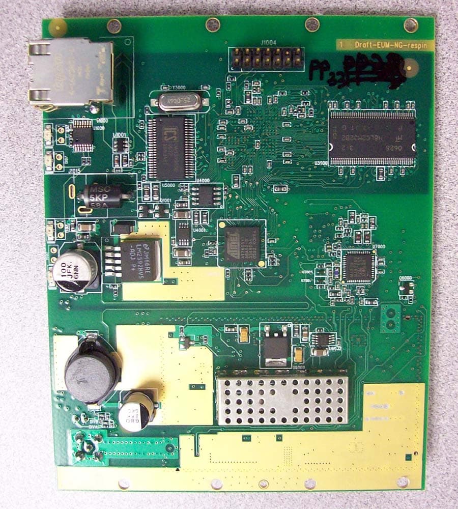
OOX-915C
Oct 23, 2007Wireless Transceiver Module
Equipment Class
DTS - Digital Transmission System
OOX-E3K6
May 10, 2006Outdoor Modem
Equipment Class
DTS - Digital Transmission System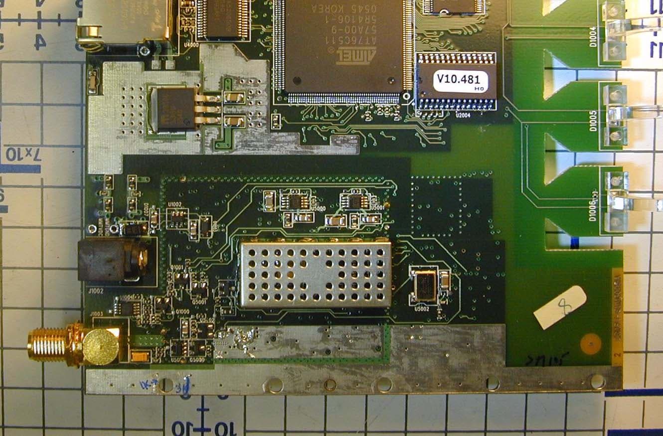
OOX-915A
Mar 27, 2006Radio Module
Equipment Class
DTS - Digital Transmission System
OOX-EUM3005
Mar 21, 2005Wireless Modem
Equipment Class
DTS - Digital Transmission System
OOX-EUM3004
Nov 10, 2003Wireless LAN end-users modem
Equipment Class
DTS - Digital Transmission System