OOX-WRM2000Wireless bridge/router model NCL1170
Vecima Networks Inc.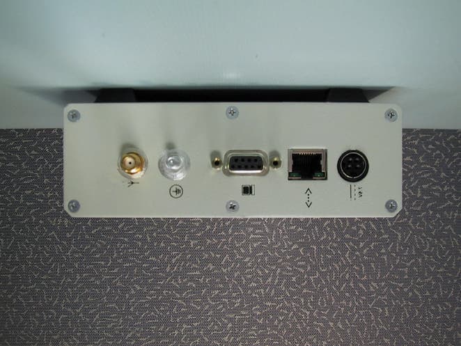
Click to zoom
Application Details
- Equipment Class
- DSS - Part 15 Spread Spectrum Transmitter
- Date of Grant
- Mar 26, 2001
- Application Purpose
- Original Equipment
- Date of Application
- Mar 26, 2001
- Equipment Note
- Wireless bridge/router model NCL1170
- Frequency Range
- 2412.00000000 - 2462.00000000
- Company
- Vecima Networks Inc.
- Country
- Canada
Documents & Files
Document Text
Text extracted from the exhibit documents filed with the FCC. Open a document above to read the original.
Users Manual
NCL1170 User Guide Version A WaveRider Communications Inc. Software License Agreement This is a legal agreement between you (either an individual or an entity) and WaveRider Communications Inc. for the use of WaveRider computer software, hereinafter the “LICENSED SOFTWARE”. By using the LICENSED SOFTWARE installed in this product, you acknowledge that you have read this license agreement, understand it, and agree to be bound by its terms. You further agree that it is the full and complete agreement between you and WaveRider Communications Inc., superseding all prior written or verbal agreements of any kind related to the LICENSED SOFTWARE. If you do not understand or do not agree to the terms of this agreement, you will cease using the LICENSED SOFTWARE immediately. 1GRANT OF LICENSE—This License Agreement permits you to use one copy of the LICENSED SOFTWARE. 2.COPYRIGHT—The LICENSED SOFTWARE is owned by WaveRider Communications Inc. and is protected by copyright laws and international treaty provisions; therefore, you must treat the LICENSED SOFTWARE like any other copyrighted material (e.g., a book or magazine). You may not copy the written materials accompanying the LICENSED SOFTWARE. 3.OTHER RESTRICTIONS—You may not rent or lease the LICENSED SOFTWARE. You may not reverse engineer, decompile, or disassemble the LICENSED SOFTWARE. 4.LIMITED WARRANTY—The LICENSED SOFTWARE is provided “as is” without any warranty of any kind, either expressed or implied, including, but not limited to, the implied warranties of merchantability and fitness for a particular purpose. The entire risk as to the quality and performance of the LICENSED SOFTWARE is with you, the licensee. If the LICENSED SOFTWARE is defective, you assume the risk and liability for the entire cost of all necessary repair, service, or correction. Some states/jurisdictions do not allow the exclusion of implied warranties, so the above exclusion may not apply to you. This warranty gives you specific legal rights, and you may have other rights, which vary from state/jurisdiction to state/jurisdiction. WaveRider Communications Inc. does not warrant that the functions contained in the LICENSED SOFTWARE will meet your requirements, or that the operation of the LICENSED SOFTWARE will be error-free or uninterrupted. 5.NO OTHER WARRANTIES—To the maximum extent permitted by applicable law, WaveRider Communications Inc. disclaims all other warranties, either express or implied, including, but not limited to, the implied warranties of merchantability and fitness for a particular purpose, with regard to the LICENSED SOFTWARE and the accompanying written materials. 6.NO LIABILITY FOR CONSEQUENTIAL DAMAGES—To the maximum extent permitted by applicable law, in no event shall WaveRider Communications Inc. or its suppliers be liable for any damages whatsoever (including, without limitation, damages for loss of business profits, business interruption, loss of business information, or any other pecuniary loss) arising from the use of or inability to use the LICENSED SOFTWARE, even if WaveRider Communications Inc. has been advised of the possibility of such damages, or for any claim by any other party. Because some states/jurisdictions do not allow the exclusion or limitation of liability for consequential or incidental damages, the above limitation may not apply to you. In no event will WaveRider’s liability exceed the amount paid for the LICENSED SOFTWARE. The following are trademarks or registered trademarks of their respective companies or organizations: Microsoft Internet Explorer / Microsoft Corporation Netscape / Netscape Communications Corporation © 2001 by WaveRider Communications Inc. All rights reserved. This manual may not be reproduced by any means in whole or in part without the express written permission of WaveRider Communications Canada Inc. Version A, January 2001 Warranty In the following warranty text, “WaveRider®” shall mean WaveRider Communications Inc. This WaveRider product is warranted against defects in material and workmanship for a period ofone (1) yearfrom the date of purchase. This limited warranty extends only to the original purchaser. During this warranty period WaveRider will, at its option, either repair or replace products that prove to be defective. For warranty service or repair, the product must be returned to a service facility designated by WaveRider. Authorization to return products must be obtained prior to shipment. The WaveRider RMA number must be on the shipping documentation so that the service facility will accept the product. The buyer shall pay all shipping charges to WaveRider and WaveRider shall pay shipping charges to return the product to the buyer within Canada or the USA. For all other countries, the buyer shall pay shipping charges as well as duties and taxes incurred in shipping products to or from WaveRider. WaveRider warrants that the firmware designed by it for use with the unit will execute its programming instructions when properly installed on the unit. WaveRider does not warrant that the operation of the unit or firmware will be uninterrupted or error-free. Limitation of Warranty The foregoing warranty shall not apply to defects resulting from improper or inadequate maintenance by the buyer, buyer-supplied interfacing, unauthorized modification or misuse, operation outside the environmental specifications for the product, or improper site preparation or maintenance or exposure to abnormal physical or electrical stress or accident. No other warranty is expressed or implied. WaveRider specifically disclaims the implied warranties of merchantability and fitness for any particular purpose. No Liability for Consequential Damages To the maximum extent permitted by applicable law, in no event shall WaveRider or its suppliers be liable for any damages whatsoever (including, without limitation, damages for loss of business profits, business interruption, loss of business information, or any other…
Text truncated - open the document above for the full version.
Users Manual
APCD–NC006–Aix Preface About this Guide This document provides a complete overview of theWaveRiderNCL1170 bridge/router, including system features, network planning, and procedures for implementing, installing, operating, and troubleshooting this device. Before proceeding, we recommend that you read the following sections: •Software License Agreementon page ii •Warrantyon page iv •Regulatory Noticeson page x •Warnings and Advisorieson page xii xAPCD–NC006–A Regulatory Notices This device has be designed to operate with several different antenna types. Each antenna type shall not exceed the maximum antenna system gain as given in the following table. Antennas having a higher gain are strictly prohibited by Industry Canada and FCC regulations. The required antenna impedance is 50 ohms. Table 1 Maximum Antenna System Gain NOTE:For a Dish antenna a cavity filter with a minimum rejection of 20 dB, ± 22MHz from the channel center frequency is required. Industry Canada The NCL1170 complies with IC RSS–210. Operators must be familiar with IC RSS–210 and RSS–102. The IC certification number for the NCL1170 is “pending”. WARNING! To prevent radio interference to the licensed service, this device is intended to be operated indoors and away from windows to provide maximum shielding. Equipment (or its transmit antenna) that is installed outdoors is subject to licensing. Federal Communications Commission The NCL1170 complies with FCC Part 15 Regulations. The FCC ID for the NCL1170 is OOX-WRM2000. The transmitter of this device complies with Part 15.247 of the FCC Rules. Antenna TypeMaximum Antenna System Gain Omni9.0 dBi Patch10.6 dBi Yagi10.1 dBi Dish20.5 dBi APCD–NC006–Axi WARNING! Operators must be familiar with the requirements of the FCC Part 15 Regulations prior to operating any link using this equipment. For installations outside the United States, contact local authorities for applicable regulations. Interference Environment Manufacturers and operators of spread-spectrum devices are reminded that the operation of these devices is subject to the conditions that: •Any received interference, including interference from industrial, scientific, and medical (ISM) operations, must be accepted; and •These devices are not permitted to cause harmful interference to other radio services. If the operation of these systems does cause harmful interference, the operator of the spread- spectrum system must correct the interference problem, even if such correction requires the Part 15 transmitter to cease operation. The FCC does not exempt spread-spectrum devices from this latter requirement regardless of the application. The FCC strongly recommends that utilities, cellular stations, public safety services, government agencies, and others that provide critical communication services exercise due caution to determine if there are any nearby radio services that can be affected by their communications. Operational Requirements In accordance with the FCC Part 15 regulations: 1. The maximum peak power output of the intentional radiator shall not exceed one (1) watt for all spread-spectrum systems operating in the 2.4000-2.4835 GHz band. 2. Systems operating in the 2.4000-2.4835 GHz band that are used exclusively for fixed, point-to-point operations may employ transmitting antennas with directional gain greater than 6 dBi, provided the maximum peak output power of the intentional radiator is reduced by 1 dB for every 3 dB that the directional gain of the antenna exceeds 6 dBi. 3. Stations operating in the 2.4000-2.4835 GHz band that are used for fixed, point-to- multipoint operations may use transmitting antennas of directional gain greater that 6 dBi, provided the peak output power from the intentional radiator is reduced by the amount in dB that the directional gain of the antenna exceeds 6 dBi. 4. Fixed, point-to-point operation, as used in Point 2, excludes the use of point-to- multipoint systems, omni-directional applications, and multiple co-located intentional radiators transmitting the same information. The operator of the spread-spectrum intentional radiator or, if the equipment is professionally installed, the installer is responsible for ensuring that the system is used exclusively for fixed, point-to-point operations. 5. The operator of a spread-spectrum system is responsible for ensuring that the system is operated in the manner outlined inInterference Environmenton page xi. xiiAPCD–NC006–A Warnings and Advisories General Advisory Operator and maintenance personnel must be familiar with the related safety requirements before they attempt to install or operate the NCL1170 equipment. It is the responsibility of the operator to ensure that the public is not exposed to excessive Radio Frequency (RF) levels. The applicable regulations can be obtained from local authorities. WARNING! This system must be professionally installed. Antennas and associated transmission cable must be installed by qualified personnel. WaveRider assumes no liability for failure to adhere to this recommendation or to recognized general safety precautions. WARNING! To comply with FCC RF exposure limits, the antenna for this transmitter must be fix-mounted on outdoor permanent structures to provide a separation distance of 2 metres (6.6 feet) from all persons to satisfy RF exposure requirements. The distance is measured from the front of the antenna and the human body. It is recommended that the antenna be installed in a location with minimal pathway disruption by nearby personnel. WARNING! Do not operate the NCL1170 without connecting a 50-ohm termination to the antenna port. This termination can be a 50-ohm antenna or a 50-ohm resistive load capable of absorbing the full RF output power of the transceiver. Failure to terminate the antenna port properly may cause permanent damage to the NCL1170. WARNING! Connect only shielded cables (both the Serial and twisted pair Ethernet) to the NCL1170 RS-232 Serial (DB-9) and 10Base Tx Ethernet …
Text truncated - open the document above for the full version.
Block Diagram
Figure 1 Block Diagram Part A PID POWER FILTERING MAC CONNECTOR +5V +3.3V +7.5V 44MHz To BBP To IQ MOD To UPConv AGC CTL DEMOD I/O MOD TxALC RFDAC RFADC IFDAC IADC QADC IFDAC IFDAC IDAC QDAC 1 1 7 6 6 6 6 7 6 LPF BASEBAND PROCESSOR 200MVpp (8.5 MHz) LPF 200MVpp (8.5 MHz) / 2 0 to 3.3V 1.0 to 2.0V 0 to 3.3V -10dBm 748MHz 200mVpp 200mVpp P = -10 to -70dBm P1dB = xdBm 0 to 3.3V 1.0 to 2.0V IQ MODULATOR BPF Rx = -75.6dBm Baseband SAW G = -8.5dB BW = 17MHz Z = 250hnms G = 9dB G = 7dB P1dB = x 2033MHz 2093MHz -10dBm BPF BPF Fc =2440MHz BW = 100MHz G = -2dB G = -4dB IF = 374MHz BW = 17MHz Upconverter Rx = -76.1dBm OFF Rx = -67.1dBm Tx = -16dBm P1dB = x P TOI = x Tx = -4.8dBm P1dB = P TOI = D C B Tx = -18dBm P1dB = PTOI = G = 17.2dB P1dB = Tx = -22dB P1dB = PTOI = Tx = -16dBm P1dB = xdBm P TOI = Tx = -24.5dBm A Fc =2440MHz BW = 100MHz G = -2dB IF RF IF VCO RF VCO Figure 2 Block Diagram Part B G = -4dB Rx = -70.1dBm Rx = -69.3dBm G = -15dB G = -0.8dB G = -0.8dBG = 23dB BPF G =-0.8dB G = -2dB BW = 100MHz LPF Rx = -88.2dBm WAVERIDER PROPRIETY CONNECTOR Tx = -10.8dBm P1dB = PTOI = G = -6dB BPF G = -2dB BW = 100MHz G = 32dB BPF G = -2dB BW = 100MHz G = 12dB Tx = 28.7dBm G = -17.2dB Gc = LOGARITHMIC DETECTORCONVERSION FOR BBP COUPLED LEVEL = 12dBm G = -0.5dB G = 0.2dB Tx = -12.8dBm P1dB = PTOI = Tx = 19.2dBm P1dB = PTOI = Tx = 17.2dBm P1dB = PTOI = Tx = 29.2dBm P1dB = PTOI = G = -0.5 D C B Rx = -88dBm Tx = -25.2dBmTx = -25.4dBm Rx = -88.7dBm Tx = -25.9dBm Rx = - 90.7dBm Tx = -27.9dBm Rx = - 91.5dBm Rx = - 92.3dBmRx = -74.1dBm Protection A GHIGH = 1 G LOW = 0 PA LNA
Cover Letter(s)
Response to TCB questions ----- Original Message ----- From: Certification Manager To: Acme Testing Sent: Thursday, February 15, 2001 2:01 PM Subject: FCC ID: OOX-WRM2000 We have completed our review and the following issues were identified: 1. Please confirm that the unit uses a single chip/symbol rate of 8:1 and that the chip/symbol rate of 11:1 available in the chip set is unused. At this time, the WRM 2000 supports only 5.5 Mbits/sec and 11 Mbits/sec CCK which uses a chip/symbol rate of 8:1. It does not support 1 Mbits/sec or 2 Mbits/sec modulation schemes which have a chip/symbol rate of 11:1. 2. Please provide bandedge plots documenting that the unit complies with the 15.205 limit at 2483.5MHz with the transmitter operating at channel 11. Use the highest gain antenna. Plots are provided for both band edges for channels 1 & 11 with the highest gain antenna 3. Please provide data responsive to the 15.31(e) requirement for input voltage variation. The transmitter was tested at 85% and 115% input voltage with no measurable change in power output. 4. The LISN was out of calibration on the date of testing. Please respond. Was it calibrated subsequently? Did the calibration return indicate that it was in calibration as received? The calibration information provided in the test report had a typographical error please see the attached revised page 12 of the test report for correct information. 5. Please explain why 24,000 MHz was selected as the upper end of the explored range when 15.33 requires exploration to the tenth harmonic or 24,620 MHz for this device. I apologize for this error and omission. The actual upper frequency range measured was 22 GHz. 22 GHz is the upper range of the HP 8566B spectrum analyzer. Previous discussions with the Engineers at the OET branch of the FCC indicated that it is an acceptable procedure to state “that by good engineering judgment and practice that if there are no detectable emissions over the range of 7.4 GHz to 22 GHz then there can be no emissions over 22 GHz”. TCB note: See FCC email exhibit 6. Please specify the label material. The material used for the Regulatory label is Mylar. Its adhesive is manufactured by 3M, part # 467MP. 7. The report specifies that testing was conducted with a shielded RS-232 cable. The users manual does not specify a shielded cable should be used when connecting to the RS-232 port. Please supply a corrected users manual. Modifications to the manual concerning the RS-232 cable. During normal operation the RS-232 cable is not attached to any of the units. It is only used for diagnostics or troubleshooting. Make modifications to the manual in the General Advisory section, under "Warnings and Advisories" , as give below: Change WARNING! Connect only shielded twisted pair (STP) Ethernet cable to the NCL1170 10Base Tx Ethernet (RJ-45) port. It is the responsibility of the installer to supply and use the correct type of Ethernet cable. To WARNING! Connect only shielded Serial and twisted pair Ethernet cables to the NCL1170 RS-232 Serial ( DB-9) and 10Base Tx Ethernet (RJ-45) ports. It is the responsibility of the installer to supply and use the correct type of Serial and Ethernet cables. 8. We have some concerns regarding the use of different antennas. We have noted the use of a unique connector but appendix D of the manual does not make it clear that the device can only be used with the tested antennas. Also for the dish antenna the gain is different from the report and on page 10 of the manual. From the test report the antenna gain results were calculated with 10m of cable and a filter. Appendix D discusses the use of different lengths. We need to be satisfied that only the tested antennas/cable/filter will be used with the device. 1)Antennas tested for use with the unit. For each type of antenna, the one with the maximum effective gain was used during test. For example the Omni antenna, with an effective gain of 9.0 dBi, was tested because it had the maximum gain that would be use with in the system. During install it could be possible to use an Omni with an effective gain of 5.0 dBi. 2) Dish Antenna Gain The report is correct, were it states the Dish Antenna gain is 24 dBi. The value stated on page 10 of the manual, referred to as the Maximum Antenna System Gain or maximum effective gain, is slightly different than antenna gain. It refers to the gain of the Antenna System which includes the antenna gain (24dBi) that is modified by losses due to cabling, filters and other passive components (3.5 dB). The maximum antenna system gain is then equal to 24-3.5=20.5 dBi. 3) Only tested antennas/cable/filter will be used with the device. a) This system is designed for commercial installations with outdoor antennas and is to be professionally installed. b) Only the antenna types tested will be used with this device. c) Only the filter tested will be used with this device. If other filters are to be second sourced they will have equivalent or superior performance and will be covered under a class I permissive change. d) Only LMR-400 or equivalent cable will be used. If other cable types are to be used they will be covered under a class I permissive change. The cable length could vary between different installations depending on the location of the antenna. But in any case, the antenna system gain will never exceed the value that unit was tested with. Thus, the radiated output RF power and spurs will be will either be equal to or less than those measured on the unit tested for FCC compliance. Best regards Barry C. Quinlan Certification & Telecom Manager Curtis-Straus LLC
External Photos
Acme Testing Co. 2002 Valley Highway PO Box 3 Acme WA 98220-0003 phone:888 226-3837 fax: 360 595-2722 Document Number: 2001015 Document Date: 9 February 2001 WaveRider Communications (Canada) Inc. FCC Part 15C (15.247) – Intentional Radiator Page 46 of 54 15. EUT Photos CHASSIS FRONT VIEW Acme Testing Co. 2002 Valley Highway PO Box 3 Acme WA 98220-0003 phone:888 226-3837 fax: 360 595-2722 Document Number: 2001015 Document Date: 9 February 2001 WaveRider Communications (Canada) Inc. FCC Part 15C (15.247) – Intentional Radiator Page 47 of 54 CHASSIS REAR VIEW Acme Testing Co. 2002 Valley Highway PO Box 3 Acme WA 98220-0003 phone:888 226-3837 fax: 360 595-2722 Document Number: 2001015 Document Date: 9 February 2001 WaveRider Communications (Canada) Inc. FCC Part 15C (15.247) – Intentional Radiator Page 48 of 54 UNIT (NEW)
ID Label/Location Info
Acme Testing Co. 2002 Valley Highway PO Box 3 Acme WA 98220-0003 phone:888 226-3837 fax: 360 595-2722 Document Number: 2001015 Document Date: 9 February 2001 WaveRider Communications (Canada) Inc. FCC Part 15C (15.247) – Intentional Radiator Page 33 of 54
Internal Photos
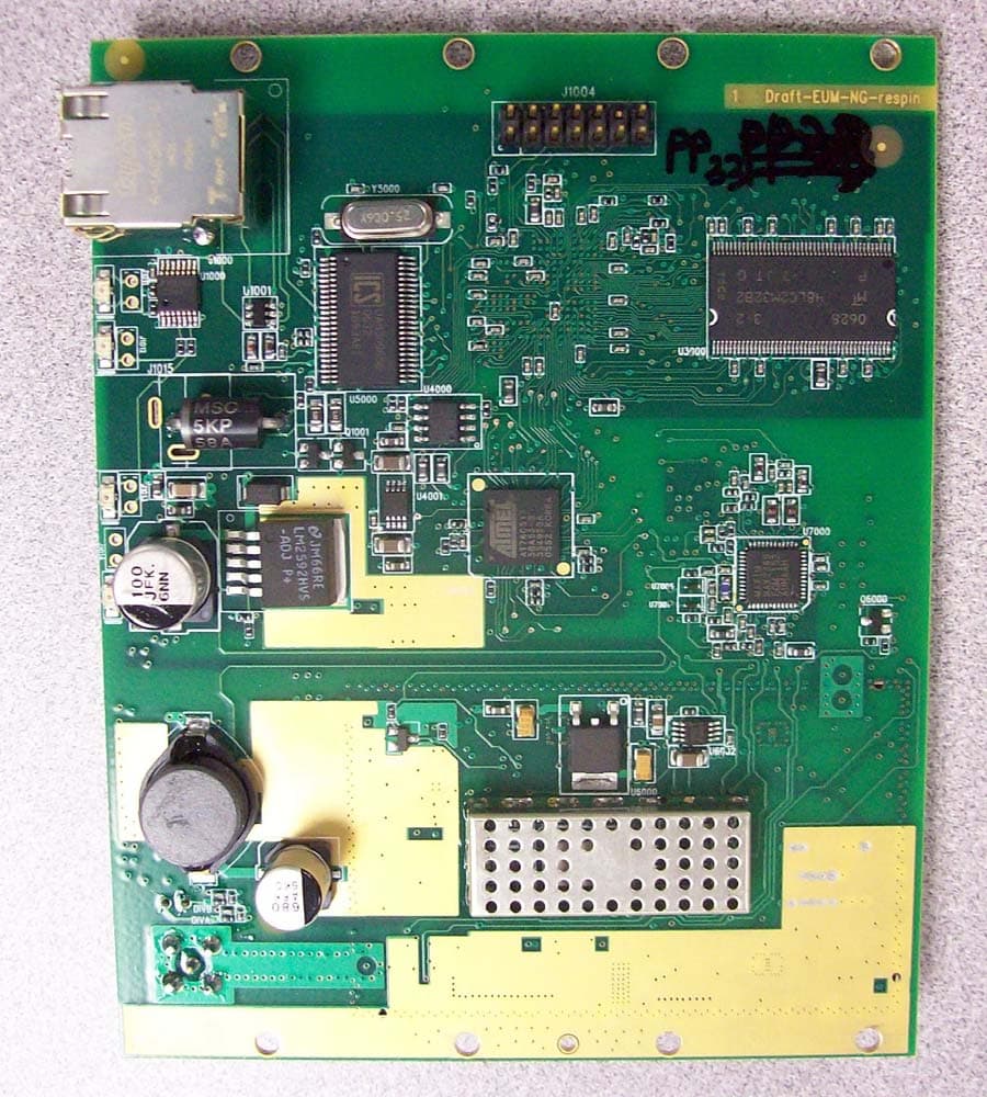
Acme Testing Co. 2002 Valley Highway PO Box 3 Acme WA 98220-0003 phone:888 226-3837 fax: 360 595-2722 Document Number: 2001015 Document Date: 9 February 2001 WaveRider Communications (Canada) Inc. FCC Part 15C (15.247) – Intentional Radiator Page 49 of 54 DIGITAL PCB TOP VIEW Acme Testing Co. 2002 Valley Highway PO Box 3 Acme WA 98220-0003 phone:888 226-3837 fax: 360 595-2722 Document Number: 2001015 Document Date: 9 February 2001 WaveRider Communications (Canada) Inc. FCC Part 15C (15.247) – Intentional Radiator Page 50 of 54 DIGITAL PCB BOTTOM VIEW Acme Testing Co. 2002 Valley Highway PO Box 3 Acme WA 98220-0003 phone:888 226-3837 fax: 360 595-2722 Document Number: 2001015 Document Date: 9 February 2001 WaveRider Communications (Canada) Inc. FCC Part 15C (15.247) – Intentional Radiator Page 51 of 54 RF & DIGITAL UNIT (NEW) Acme Testing Co. 2002 Valley Highway PO Box 3 Acme WA 98220-0003 phone:888 226-3837 fax: 360 595-2722 Document Number: 2001015 Document Date: 9 February 2001 WaveRider Communications (Canada) Inc. FCC Part 15C (15.247) – Intentional Radiator Page 52 of 54 RF PCB FRONT VIEW – WITH SHIELDS Acme Testing Co. 2002 Valley Highway PO Box 3 Acme WA 98220-0003 phone:888 226-3837 fax: 360 595-2722 Document Number: 2001015 Document Date: 9 February 2001 WaveRider Communications (Canada) Inc. FCC Part 15C (15.247) – Intentional Radiator Page 53 of 54 RF PCB FRONT VIEW – WITH SHIELDS REMOVED
Operational Description
WRM-2000 Functional Overview The WRM-2000 radio module is based on the Intersil PRISM II Direct Sequence Chip Set. As shown in the block diagram located in Figure 1 and 2, there are ten basic units in this module: 1. Baseband Processor 2. Modulator/Demodulator 3. Dual Synthesizer 4. Up/Down Converter 5. Power Amplifier 6. Low Noise Amplifier (LNA) 7. RF VCO 8. IF VCO 9. Antenna (RF) Interface 10. MAC/Radio (buffered) Interface During transmission, the data to be transmitted is placed on the Baseband Processor TX data line. This data is modulated according to the format selected (CCK) and then spread using a defined PN code. Two signals are generated (the In-Phase (I) and Quadrature (Q) components). The I & Q signals are sent to the Modulator/Demodulator where they are first filtered and then modulated with the IF frequency (374 MHz). The IF oscillator generates a 748 MHz signal which is divided by two inside the Modulator/Demodulator, generating a final IF signal of 374 MHz. Next, the two signals are combined into a single signal and sent to the Up/Down converter. The Up/Down converter will shift this signal to the RF frequency for the channel programmed in the synthesizer, for operation within the 2.4GHz ISM band. In the final stage, this signal is amplified to produce +25 dBm RF power output as measured at the output of the antenna port. In the receive mode, the radio signal is amplified by the LNA, and then sent to the Up/Down converter. The Up/Down converter down-converts this signal from the 2.4GHz range to the IF frequency, 374MHz. The Modulator/Demodulator then converts the signal to baseband and splits the signal into its I & Q components, before sending it to the Baseband Processor. Finally, the Baseband Processor despreads and demodulates the data contained in the CCK format, and places it on the RX data line. Bi-directional, translating buffers are used to interface between controller (5V) and radio module (3.5V) logic levels. The RF and IF Local Oscillator signals are generated using the synthesizer and voltage controlled oscillators. The dual synthesizer is programmed with the desired RF channel frequency less the IF frequency. The baseband processor and the synthesizer are driven from a common 44MHz oscillator to control the timing of these chips. Example (for Channel 1 operation): RF IF LO 2412 MHz – 374 MHz = 2038 MHz The antenna (RF) connector is connected to a 50-ohm impedance matched transmission line (Times Microwave LMR-400 or LMR-600) to one of the following antenna types: Omni, Patch, Yagi and Dish. The table below includes examples of each of the recommended antenna types, as well as their associated maximum antenna system gain. Antenna Type Manufacturer Model Number Maximum Antenna System Gain Omni Mobile Mark OD9-2400 9.0 dBi Patch Til-Tek TA-2408 10.6 dBi Yagi Astron 928-4 10.1 dBi Dish 1 Til-Tek TA-811 20.5 dBi Table 1: Antenna Type for use with the NCL11 1 A cavity filter with a minimum rejection of 20 dB ± 22 MHz from the channel center frequency is required. i.e. TTE-07766 or equivalent. Figure 1 Block Diagram Part A PID POWER FILTERING MAC CONNECTOR +5V +3.3V +7.5V 44MHz To BBP To IQ MOD To UPConv AGC CTL DEMOD I/O MOD TxALC RFDAC RFADC IFDAC IADC QADC IFDAC IFDAC IDAC QDAC 1 1 7 6 6 6 6 7 6 LPF BASEBAND PROCESSOR 200MVpp (8.5 MHz) LPF 200MVpp (8.5 MHz) / 2 0 to 3.3V 1.0 to 2.0V 0 to 3.3V -10dBm 748MHz 200mVpp 200mVpp P = -10 to -70dBm P1dB = xdBm 0 to 3.3V 1.0 to 2.0V IQ MODULATOR BPF Rx = -75.6dBm Baseband SAW G = -8.5dB BW = 17MHz Z = 250hnms G = 9dB G = 7dB P1dB = x 2033MHz 2093MHz -10dBm BPF BPF Fc =2440MHz BW = 100MHz G = -2dB G = -4dB IF = 374MHz BW = 17MHz Upconverter Rx = -76.1dBm OFF Rx = -67.1dBm Tx = -16dBm P1dB = x P TOI = x Tx = -4.8dBm P1dB = P TOI = D C B Tx = -18dBm P1dB = PTOI = G = 17.2dB P1dB = Tx = -22dB P1dB = PTOI = Tx = -16dBm P1dB = xdBm P TOI = Tx = -24.5dBm A Fc =2440MHz BW = 100MHz G = -2dB IF RF IF VCO RF VCO Figure 2 Block Diagram Part B G = -4dB Rx = -70.1dBm Rx = -69.3dBm G = -15dB G = -0.8dB G = -0.8dBG = 23dB BPF G =-0.8dB G = -2dB BW = 100MHz LPF Rx = -88.2dBm WAVERIDER PROPRIETY CONNECTOR Tx = -10.8dBm P1dB = PTOI = G = -6dB BPF G = -2dB BW = 100MHz G = 32dB BPF G = -2dB BW = 100MHz G = 12dB Tx = 28.7dBm G = -17.2dB Gc = LOGARITHMIC DETECTORCONVERSION FOR BBP COUPLED LEVEL = 12dBm G = -0.5dB G = 0.2dB Tx = -12.8dBm P1dB = PTOI = Tx = 19.2dBm P1dB = PTOI = Tx = 17.2dBm P1dB = PTOI = Tx = 29.2dBm P1dB = PTOI = G = -0.5 D C B Rx = -88dBm Tx = -25.2dBmTx = -25.4dBm Rx = -88.7dBm Tx = -25.9dBm Rx = - 90.7dBm Tx = -27.9dBm Rx = - 91.5dBm Rx = - 92.3dBmRx = -74.1dBm Protection A GHIGH = 1 G LOW = 0 PA LNA
Test Report
Acme Testing Co. 2002 Valley Highway PO Box 3 Acme WA 98220-0003 phone:888 226-3837 fax: 360 595-2722 Document Number: 2001015 Document Date: 9 February 2001 WaveRider Communications (Canada) Inc. FCC Part 15C (15.247) – Intentional Radiator Page 1 of 54 REPORT OF MEASUREMENTS PART 15C (15.247) - INTENTIONAL RADIATOR DEVICE: 2.4 GHZ 11 CHANNEL DIRECT SEQUENCE SPREAD SPECTRUM WIRELESS ROUTER/BRIDGE MODEL: NCL1170 MANUFACTURER: WAVERIDER COMMUNICATIONS (CANADA) INC. ADDRESS: 6120 – 1A STREET S.W. CALGARY ALBERTA CANADA T2H 0G3 WORK ORDER: 9181HR Acme Testing Co. 2002 Valley Highway PO Box 3 Acme WA 98220-0003 phone:888 226-3837 fax: 360 595-2722 Document Number: 2001015 Document Date: 9 February 2001 WaveRider Communications (Canada) Inc. FCC Part 15C (15.247) – Intentional Radiator Page 2 of 54 Acme Testing Co. 2002 Valley Highway PO Box 3 Acme WA 98220-0003 phone:888 226-3837 fax: 360 595-2722 Document Number: 2001015 Document Date: 9 February 2001 WaveRider Communications (Canada) Inc. FCC Part 15C (15.247) – Intentional Radiator Page 3 of 54 1. GENERAL...............................................................................................................................................................5 1.1 DOCUMENT HISTORY...........................................................................................................................................5 1.2 PURPOSE.............................................................................................................................................................6 1.3 MANUFACTURER.................................................................................................................................................7 1.4 TEST LOCATION...................................................................................................................................................7 1.5 ACCREDITATION AND LISTING.............................................................................................................................7 2. TEST RESULTS SUMMARY.................................................................................................................................8 3. DESCRIPTION OF EQUIPMENT AND PERIPHERALS....................................................................................9 3.1 EQUIPMENT UNDER TEST (EUT)..........................................................................................................................9 3.2 MODE OF OPERATION DURING TESTING...............................................................................................................9 3.3 MODIFICATIONS REQUIRED FOR COMPLIANCE.......................................................................................................9 3.4 EUT PERIPHERALS FOR EMISSIONS......................................................................................................................9 3.5 DESCRIPTION OF INTERFACE CABLES FOR EMISSIONS..........................................................................................10 4. ANTENNA REQUIREMENT...............................................................................................................................11 4.1 REGULATION.....................................................................................................................................................11 4.2 RESULT.............................................................................................................................................................11 5. CONDUCTED EMISSIONS TESTS...............................................…
Text truncated - open the document above for the full version.
Contact Information
Applicant
Lawrence Gordon(Senior Technical Design Lead)
Test Firm
Acme Testing Co.Harry Hodes
Technical Specifications
| # | Rule Parts | Frequency Range | Power Output |
|---|---|---|---|
| 1 | 15C | 2.41 GHz - 2.46 GHz | 338.00 mW |
Other Applications from Vecima Networks Inc.
OOX-915C
Oct 23, 2007Wireless Transceiver Module
Equipment Class
DTS - Digital Transmission System
OOX-E3K6
May 10, 2006Outdoor Modem
Equipment Class
DTS - Digital Transmission System
OOX-915A
Mar 27, 2006Radio Module
Equipment Class
DTS - Digital Transmission System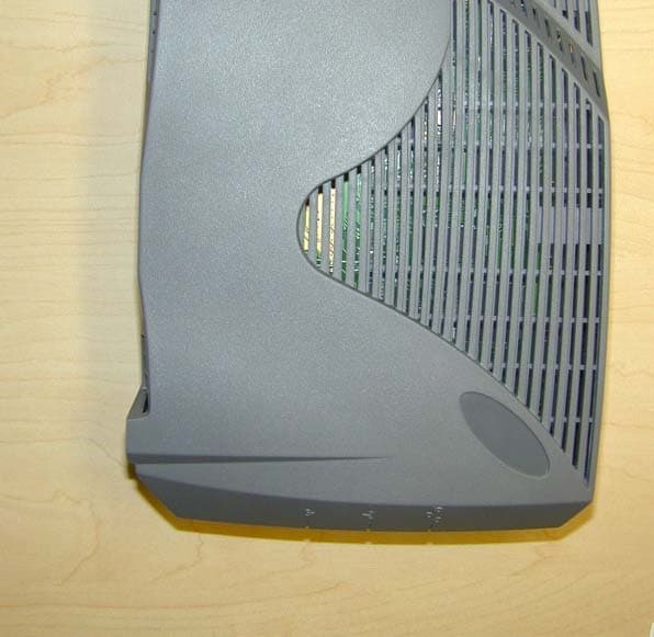
OOX-EUM3005
Mar 21, 2005Wireless Modem
Equipment Class
DTS - Digital Transmission System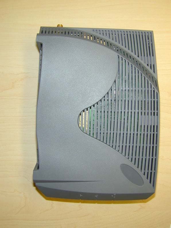
OOX-EUM3004
Nov 10, 2003Wireless LAN end-users modem
Equipment Class
DTS - Digital Transmission System