OOX-WRM3200CCU3200
Vecima Networks Inc.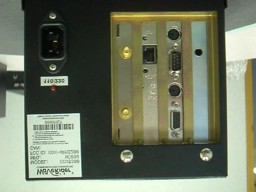
Click to zoom
Application Details
- Equipment Class
- DSS - Part 15 Spread Spectrum Transmitter
- Date of Grant
- Nov 02, 2000
- Application Purpose
- Original Equipment
- Date of Application
- Nov 02, 2000
- Equipment Note
- CCU3200
- Frequency Range
- 905.00000000 - 925.00000000
- Company
- Vecima Networks Inc.
- Country
- Canada
Documents & Files
Document Text
Text extracted from the exhibit documents filed with the FCC. Open a document above to read the original.
Users Manual
1 of 2 LMS3200 User Guide Updates to the LMS3200 User Guide to reflect the following changes: •“2 metres" in place of "32cm" in a Warning statement within the Regulatory Notices sec- tion •Within the "Regulatory Notices" and "Installation" sections include an additional Warning statement that reads "A shielded RS-232 cable must be used on the console port of the device. It is the responsibility of the installer to supply and install a shielded RS-232 cable.” Regulatory Notice Additions WARNING! To comply with FCC RF exposure limits, the antenna for this transmitter must befix-mounted on outdoor permanent structures to provide a separation distance of 2 metres (6.6 feet) or more from all persons to satisfy RF exposure requirements. The distance is measured between the front of the antenna and the human body. It is recommended that the antenna be installed in a location with minimal pathway disruption by nearby personnel. LMS3200 Errata APCD–LM019–A — LMS3200 ERRATA — November 01, 2000 2 of 2 WARNING! A shielded RS-232 cable must be used on the console port of the device. It is the responsibility of the installer to supply and install a shielded RS-232 cable. Adding an EUM Section Addition WARNING! A shielded RS-232 cable must be used on the console port of the device. It is the responsibility of the installer to supply and install a shielded RS-232 cable.
Users Manual
LMS3200 User Guide Version A WaveRider Communications Inc. Software License Agreement This is a legal agreement between you (either an individual or an entity) and WaveRider Communications Inc. for the use of WaveRider computer software, hereinafter the “LICENSED SOFTWARE”. By using the LICENSED SOFTWARE installed in this product, you acknowledge that you have read this license agreement, understand it, and agree to be bound by its terms. You further agree that it is the full and complete agreement between you and WaveRider Communications Inc., superseding all prior written or verbal agreements of any kind related to the LICENSED SOFTWARE. If you do not understand or do not agree to the terms of this agreement, you will cease using the LICENSED SOFTWARE immediately. 1GRANT OF LICENSE—This License Agreement permits you to use one copy of the LICENSED SOFTWARE. 2.COPYRIGHT—The LICENSED SOFTWARE is owned by WaveRider Communications Inc. and is protected by copyright laws and international treaty provisions; therefore, you must treat the LICENSED SOFTWARE like any other copyrighted material (e.g., a book or magazine). You may not copy the written materials accompanying the LICENSED SOFTWARE. 3.OTHER RESTRICTIONS—You may not rent or lease the LICENSED SOFTWARE. You may not reverse engineer, decompile, or disassemble the LICENSED SOFTWARE. 4.LIMITED WARRANTY—The LICENSED SOFTWARE is provided “as is” without any warranty of any kind, either expressed or implied, including, but not limited to, the implied warranties of merchantability and fitness for a particular purpose. The entire risk as to the quality and performance of the LICENSED SOFTWARE is with you, the licensee. If the LICENSED SOFTWARE is defective, you assume the risk and liability for the entire cost of all necessary repair, service, or correction. Some states/jurisdictions do not allow the exclusion of implied warranties, so the above exclusion may not apply to you. This warranty gives you specific legal rights, and you may have other rights, which vary from state/jurisdiction to state/jurisdiction. WaveRider Communications Inc. does not warrant that the functions contained in the LICENSED SOFTWARE will meet your requirements, or that the operation of the LICENSED SOFTWARE will be error-free or uninterrupted. 5.NO OTHER WARRANTIES—To the maximum extent permitted by applicable law, WaveRider Communications Inc. disclaims all other warranties, either express or implied, including, but not limited to, the implied warranties of merchantability and fitness for a particular purpose, with regard to the LICENSED SOFTWARE and the accompanying written materials. 6.NO LIABILITY FOR CONSEQUENTIAL DAMAGES—To the maximum extent permitted by applicable law, in no event shall WaveRider Communications Inc. or its suppliers be liable for any damages whatsoever (including, without limitation, damages for loss of business profits, business interruption, loss of business information, or any other pecuniary loss) arising from the use of or inability to use the LICENSED SOFTWARE, even if WaveRider Communications Inc. has been advised of the possibility of such damages, or for any claim by any other party. Because some states/jurisdictions do not allow the exclusion or limitation of liability for consequential or incidental damages, the above limitation may not apply to you. In no event will WaveRider’s liability exceed the amount paid for the LICENSED SOFTWARE. The following are trademarks or registered trademarks of their respective companies or organizations: Microsoft Windows NT 4.0 Workstation (with Service Pack 6a), Microsoft Access, Microsoft SQL Server, Microsoft SQL Agent / Microsoft Corporation Vircom VOP Radius Server / Vircom Inc. Castlerock SNMPc Server / Castle Rock Computing Tardis Timeserver / H.C. Mingham-Smith Ltd. APS PowerChute PLUS / American Power Conversion CD-Writer Plus / Hewlett Packard Company 3200 Color Jetprinter / Lexmark International Inc. Veritas Backup Exec / VERITAS Software © 2000 by WaveRider Communications Inc. All rights reserved. This manual may not be reproduced by any means in whole or in part without the express written permission of WaveRider Communications Canada Inc. Version A, September 2000 Warranty In the following warranty text, “WaveRider®” shall mean WaveRider Communications Inc. This WaveRider product is warranted against defects in material and workmanship for a period of one (1) year from the date of purchase. During this warranty period WaveRider will, at its option, either repair or replace products that prove to be defective. For warranty service or repair, the product must be returned to a service facility designated by WaveRider. Authorization to return products must be obtained prior to shipment. The WaveRider RMA number must be on the shipping documentation so that the service facility will accept the product. The buyer shall pay all shipping charges to WaveRider and WaveRider shall pay shipping charges to return the product to the buyer within Canada or the USA. For all other countries, the buyer shall pay shipping charges as well as duties and taxes incurred in shipping products to or from WaveRider. WaveRider warrants that the firmware designed by it for use with the unit will execute its programming instructions when properly installed on the unit. WaveRider does not warrant that the operation of the unit or firmware will be uninterrupted or error-free. Limitation of Warranty The foregoing warranty shall not apply to defects resulting from improper or inadequate maintenance by the buyer, buyer-supplied interfacing, unauthorized modification or misuse, operation outside the environmental specifications for the product, or improper site preparation or maintenance. No other warranty is expressed or implied. WaveRider specifically disclaims the implied warranties of merchantability and fitness for any particular purpose. No Liability for Consequential Damages To the maximum extent permitted by a…
Text truncated - open the document above for the full version.
Users Manual
1 of 2 LMS3200 User Guide Updates to the LMS3200 User Guide to reflect the following changes: •“2 metres" in place of "32cm" in a Warning statement within the Regulatory Notices sec- tion •Within the "Regulatory Notices" and "Installation" sections include an additional Warning statement that reads "A shielded RS-232 cable must be used on the console port of the device. It is the responsibility of the installer to supply and install a shielded RS-232 cable.” Regulatory Notice Additions WARNING! To comply with FCC RF exposure limits, the antenna for this transmitter must befix-mounted on outdoor permanent structures to provide a separation distance of 2 metres (6.6 feet) or more from all persons to satisfy RF exposure requirements. The distance is measured between the front of the antenna and the human body. It is recommended that the antenna be installed in a location with minimal pathway disruption by nearby personnel. LMS3200 Errata APCD–LM019–A — LMS3200 ERRATA — November 01, 2000 2 of 2 WARNING! A shielded RS-232 cable must be used on the console port of the device. It is the responsibility of the installer to supply and install a shielded RS-232 cable. Adding an EUM Section Addition WARNING! A shielded RS-232 cable must be used on the console port of the device. It is the responsibility of the installer to supply and install a shielded RS-232 cable.
Block Diagram
WaveRider Communications WRM3200 Functional Block Diagram Date: September 18, 2000. Prepared by: Approved by: WRM3200 FUNCTIONAL BLOCK DIAGRAM RF Front End and Frequency Synthesizer SIZEFSCM NODWG NOREV b1.0 SCALE N/A SHEET 1 OF2 11.0592MHz PLL Freq. Synthesizer Reference Clock RF LO 1195 MHz IF LO 560 MHz IF SAW BPF IF SAW BPF ANTENNA A/B SWITCH 2 POLE CERAMIC BPF TX/RX SWITCH LNA 2nd LNA 2 POLE CERAMIC BPF DOWNCONVERTERIF AMP RF LO BUFFER RF LO BUFFER IF AMP 2 POLE CERAMIC BPF UPCONVERTER TX DRIVER AMPTX POWER AMP RX IF to DEMOD TX IF from MODULATOR IF LO to Modem IC 280 MHz 280 MHz 915 MHz 915 MHz 915 MHz WRM3200 FUNCTIONAL BLOCK DIAGRAM Modulator/Demodulator and Baseband Processor SIZEFSCM NODWG NOREV b1.0 SCALE N/A SHEET 2 OF2 RX IF from FRONT END TX IF to FRONT END IF LO from PLL HFA3724 Modulator/ Demodualator HFA3860B Baseband Processor RX I RX Q TX I TX Q RSSI Bi-directional Buffer/ Translater CMC Connector Data and Control LinesData and Control Lines
External Photos
Disc antenna Omni-directional antenna Patch antenna Yagi antenna
Operational Description
WRM-3200 Functional Overview The WRM-3200 radio module is based on the Intersil PRISM Direct Sequence Chip Set. There are ten basic units in this module: 1. Baseband Processor 2. Modulator/Demodulator 3. Dual Synthesizer 4. Up/Down Converter 5. Power Amplifier 6. Low Noise Amplifier (LNA) 7. RF VCO 8. IF VCO 9. Antenna (RF) Interface 10. MAC/Radio (buffered) Interface During transmission, the data to be transmitted is placed on the TX data line going into the baseband processor. This data is modulated according to the format selected (CCK) and then spread using a defined PN code. Two signals will be generated (I & Q). The I & Q signals are sent to the Modulator/Demodulator where they will be first filtered and then modulated with the IF frequency (280MHz). The IF oscillator generates 560MHz which is divided by two inside the Modulator/Demodulator, so the final IF signal is 280MHz. Next, the two signals are combined into a single signal and sent over to the Up/Down converter. The Up/Down converter will shift this signal to the RF channel programmed in the synthesizer, in the 902 – 928 MHz ISM band. In the final stage, this signal is amplified to produce a typical power output of +25dBm, measured in the middle of the ISM Band at the antenna. In receive mode, if antenna diversity is enabled the radio selects the antenna with the strongest received signal, otherwise it defaults to the transmit antenna. This signal is amplified by the LNA, and then sent to the Up/Down converter. The Up/Down converter down-converts this signal from the 902 – 928 MHz range to the IF frequency, 280MHz. The Modulator/Demodulator converts the signal to baseband and splits the signal into the In-Phase (I) and Quadrature (Q) components, before it is sent to the Baseband Processor. Finally, the Baseband Processor despreads and demodulates the data from CCK form, and places it on the RX data line. Bi-directional, translating buffers are used to interface between controller (5V) and radio module (3.5V) logic levels. The RF and IF Local Oscillator signals are generated using the synthesizer and the voltage controlled oscillators. The dual synthesizer is programmed with the desired RF channel frequency less the IF frequency. The baseband processor and the synthesizer are driven from a common 11.0592 MHz oscillator to control the timing of these chips. Example (for Channel 1 operation): RF IF LO 905 MHz – 280 MHz = 625 MHz The antenna (RF) interface is connected to a 50-ohm impedance matched transmission line (Times Microwave LMR-400 or LMR-600) and one of the following antennas: • Astron V-9183, 5.14 dBi gain, omni - for CCU; • Astron ASTPCG09, 8.5 dBi gain, 90-degree patch - for CCU; • Astron 918-4, 9.14 dBi gain, yagi - for EUM (outdoor); • Astron AXQ9RPSMS 'rubber-ducky' antenna – for EUM (indoor); • Astron PCNLP-09V, 3 dBi gain, low profile disc - for EUM (indoor or outdoor). The radio module (analog) ground system is isolated from the controller (digital) ground system throughout the various stages of the radio. The grounds are, however, connected at a single point (power supply). This practice will ensure that the digital ground is not modulated by the analog ground, as the PA switches on and off. Furthermore, proper grounding practice minimizes EMI/EMC issues. The antenna system is grounded to the site primary ground system, and protection is provided through the use of gas-element surge/lightning protectors. Figure 1: Block Diagram of the RF Front End and Frequency Synthesizer Figure 1: Block Diagram of the Modulator/Demodulator and Baseband Processor 11.0592MHz PLL Freq. Synthesizer Reference Clock RF LO 1195 MHz IF LO 560 MHz IF SAW BPF IF SAW BPF ANTENNA A/B SWITCH 2 POLE CERAMIC BPF TX/RX SWITCH LNA 2nd LNA 2 POLE CERAMIC BPF DOWNCONVERTER IF AMP RF LO BUFFER RF LO BUFFER IF AMP 2 POLE CERAMIC BPF UPCONVERTER TX DRIVER AMP TX POWER AMP RX IF to DEMOD TX IF from MODULATOR IF LO to Modem IC 280 MHz 280 MHz 915 MHz 915 MHz 915 MHz RX IF from FRONT END TX IF to FRONT END IF LO from PLL HFA3724 Modulator/ Demodulator HFA3860B Baseband Processor RX I RX Q TX I TX Q RSSI Bi-directional Buffer/ Translator CMC Connector Data and Control Lines Data and Control Lines
Test Report
DATE OF ISSUANCE: 28 SEPTEMBER 2000 REPORT NUMBER: 20000209 FCC ID: OOX-WRM3200 PAGE 1 OF 24 Partial reproduction of this document is prohibited without prior written consent of Acme Testing Inc. ACME TESTING INC., 2002 VALLEY HWY, P.O. BOX 3, ACME, WASHINGTON 98220-0003 888-226-3837. REPORT OF MEASUREMENTS PART 15C (15.247) - INTENTIONAL RADIATOR DEVICE: 905 - 925 MHz 41 CHANNEL DIRECT SEQUENCE SPREAD SPECTRUM TRANSCEIVER MODEL: CCU3200 MANUFACTURER: WAVERIDER COMMUNICATIONS (CANADA) INC. ADDRESS: 6120 – 1A STREET S.W. CALGARY ALBERTA CANADA T2H 0G3 THE DATA CONTAINED IN THIS REPORT WAS COLLECTED ON 1, 11, & 24 AUGUST 2000 AND COMPILED BY: PAUL G. SLAVENS CHIEF EMC ENGINEER WORK ORDER: 23500HR DATE OF ISSUANCE: 28 SEPTEMBER 2000 REPORT NUMBER: 20000209 FCC ID: OOX-WRM3200 PAGE 2 OF 24 1. GENERAL..............................................................................................................................................................................................4 1.1 PURPOSE........................................................................................................................................................................................4 1.2 MANUFACTURER.........................................................................................................................................................................4 1.3 TEST LOCATION...........................................................................................................................................................................4 1.4 TEST PERSONNEL.........................................................................................................................................................................4 2. TEST RESULTS SUMMARY.............................................................................................................................................................5 3. DESCRIPTION OF EQUIPMENT AND PERIPHERALS.............................................................................................................6 3.1 EQUIPMENT UNDER TEST (EUT)..............................................................................................................................................6 3.2 EUT PERIPHERALS.......................................................................................................................................................................6 3.3 DESCRIPTION OF INTERFACE CABLES FOR EMISSIONS..........................................................................................................6 3.4 MODE OF OPERATION DURING TESTS.....................................................................................................................................6 3.5 MODIFICATIONS REQUIRED FOR COMPLIANCE.....................................................................................................................6 4. ANTENNA REQUIREMENT..............................................................................................................................................................7 4.1 REGULATION................................................................................................................................................................................7 4.2 RESULT..........................................................................................................................................................................................7 5. CONDUCTED EMISSIONS TESTS.................................................................................................................................................8 5.1 TEST EQUIPMENT........................................................................................................................................................................8 5.2 PURPOSE........................................................................................................................................................................................8 5.3 TEST PROCEDURES......................................................................................................................................................................8 5.4 TEST RESULTS..............................................................................................................................................................................9 6. 6 DB BANDWIDTH.........................................................................................................................................................................10 6.1 REGULATION..............................................................................................................................................................................10 6.2 TEST EQUIPMENT......................................................................................................................................................................10 6.3 TEST PROCEDURES....................................................................................................................................................................10 6.4 TEST RESULTS............................................................................................................................................................................10 7. POWER OUTPUT.............................................................................................................................................................................11 7.1 REGULATION..............................................................................................................................................................................11 7.2 TEST EQUIPMENT......................................................................................................................................................................11 7.3 TEST PROCEDURES...........…
Text truncated - open the document above for the full version.
Test Report
DATE OF ISSUANCE: 28 SEPTEMBER 2000 REPORT NUMBER: 20000209 FCC ID: OOX-WRM3200 PAGE 1 OF 24 Partial reproduction of this document is prohibited without prior written consent of Acme Testing Inc. ACME TESTING INC., 2002 VALLEY HWY, P.O. BOX 3, ACME, WASHINGTON 98220-0003 888-226-3837. REPORT OF MEASUREMENTS PART 15C (15.247) - INTENTIONAL RADIATOR DEVICE: 905 - 925 MHz 41 CHANNEL DIRECT SEQUENCE SPREAD SPECTRUM TRANSCEIVER MODEL: CCU3200 MANUFACTURER: WAVERIDER COMMUNICATIONS (CANADA) INC. ADDRESS: 6120 – 1A STREET S.W. CALGARY ALBERTA CANADA T2H 0G3 THE DATA CONTAINED IN THIS REPORT WAS COLLECTED ON 1, 11, & 24 AUGUST 2000 AND COMPILED BY: PAUL G. SLAVENS CHIEF EMC ENGINEER WORK ORDER: 23500HR 1. GENERAL.............................................................................................................................................................4 DATE OF ISSUANCE: 28 SEPTEMBER 2000 REPORT NUMBER: 20000209 FCC ID: OOX-WRM3200 PAGE 2 OF 24 1.1 PURPOSE...........................................................................................................................................................4 1.2 MANUFACTURER...............................................................................................................................................4 1.3 TEST LOCATION.................................................................................................................................................4 1.4 TEST PERSONNEL..............................................................................................................................................4 2. TEST RESULTS SUMMARY...............................................................................................................................5 3. DESCRIPTION OF EQUIPMENT AND PERIPHERALS..................................................................................6 3.1 EQUIPMENT UNDER TEST (EUT)........................................................................................................................6 3.2 EUT PERIPHERALS............................................................................................................................................6 3.3 DESCRIPTION OF INTERFACE CABLES FOR EMISSIONS..........................................................................................6 3.4 MODE OF OPERATION DURING TESTS.................................................................................................................6 3.5 MODIFICATIONS REQUIRED FOR COMPLIANCE.....................................................................................................6 4. ANTENNA REQUIREMENT...............................................................................................................................7 4.1 REGULATION.....................................................................................................................................................7 4.2 RESULT.............................................................................................................................................................7 5. CONDUCTED EMISSIONS TESTS.....................................................................................................................8 5.1 TEST EQUIPMENT..............................................................................................................................................8 5.2 PURPOSE...........................................................................................................................................................8 5.3 TEST PROCEDURES............................................................................................................................................8 5.4 TEST RESULTS...................................................................................................................................................9 6. 6 DB BANDWIDTH............................................................................................................................................10 6.1 REGULATION...................................................................................................................................................10 6.2 TEST EQUIPMENT............................................................................................................................................10 6.3 TEST PROCEDURES..........................................................................................................................................10 6.4 TEST RESULTS.................................................................................................................................................10 7. POWER OUTPUT...............................................................................................................................................11 7.1 REGULATION...................................................................................................................................................11 7.2 TEST EQUIPMENT............................................................................................................................................11 7.3 TEST PROCEDURES..........................................................................................................................................11 7.4 TEST RESULTS.................................................................................................................................................11 8. ANTENNA GAIN REQUIREMENTS................................................................................................................12 8.1 REGULATION...................................................................................................................................................12 8.2 RESULT.................................................................................................................................…
Text truncated - open the document above for the full version.
Test Report
Responses to TCB questions I believe this is the last of the requested information. Could you confirm whether or not there are any outstanding issues? Regards, Desiree ----- Original Message ----- From: "Correen Clarke" <[email protected] > To: <[email protected] >; "Acme Testing" <[email protected]> Sent: Wednesday, November 01, 2000 2:43 PM Subject: Re: OOX-WRM3200 *PRIORITY* > Desiree, > > As per our earlier conversation here is the attachment with the correct > icons for the warnings and the document number. > > Please call me if you have any questions or concerns. > > Regards, > > Correen Clarke > Document Controller/Project Manager > WaveRider Communications Inc. > Tel:(403) 301-4530 > Fax:(403)640-9114 > > Email: [email protected] > www.waverider.com > ----- Original Message ----- > From: "Ivan Rodrigues" <[email protected] > > To: "Acme Testing" <[email protected]> > Sent: Wednesday, November 01, 2000 1:24 PM > Subject: RE: OOX-WRM3200 *PRIORITY* > > > > Desiree, > > > > Sorry for the delay... attached is the necessary Errata sheet for the > > LMS3200 manuals. > > > > Please let me know what the status is on our IC and FCC certifications. I > > assume that this Errata satisfies all outstanding submission requirements. > > > > Cheerz, > > Ivan > > > > -----Original Message----- > > From: Acme Testing [mailto:[email protected] ] > > Sent: Wednesday, November 01, 2000 10:57 AM > > To: [email protected] > > Subject: Re: OOX-WRM3200 *PRIORITY* > > > > > > Ivan, > > > > Do you know the status of the User Manual? > > > > Thanks, > > > > Desiree > > ----- Original Message ----- > > From: "Ivan Rodrigues" <[email protected] > > > To: "Acme Testing" <[email protected]> > > Sent: Tuesday, October 24, 2000 6:55 AM > > Subject: RE: OOX-WRM3200 *PRIORITY* > > > > > > > Desiree, > > > > > > I will get the updated manual to you ASAP. > > > > > > Cheerz, > > > Ivan > > > > > > -----Original Message----- > > > From: Acme Testing [mailto:[email protected] ] > > > Sent: Tuesday, October 24, 2000 10:53 AM > > > To: [email protected] > > > Subject: Fw: OOX-WRM3200 *PRIORITY* > > > > > > > > > Dear Ivan, > > > > > > Do you have a revised User Manual with the Warning statment yet. Also, > > > there needs to be a statement regarding the sheilded RS-232 cable that > is > > > used. > > > > > > Regards, > > > > > > Desiree > > > > > > > > > > > > > > > However as testing was conducted with a shielded RS-232 cable the > > > installation guide needs to state a shielded RS-232 should be used. > Refer > > to > > > Part 15.27(b). We are also waiting for the revised installation guide > with > > > the people/antenna distance changed to 2 meters. ----- Original Message ----- From: Ivan Rodrigues To: Acme Testing Sent: Monday, October 23, 2000 9:59 AM Subject: RE: WaveRider FCC ID: OOX-WRM3200 Desiree, 1. Here are better quality photos of the WRM-3200 with the RF shields removed. 2. The Product Label is permanent and may not be removed or reapplied without damage. Cheerz, --------------------------------------------------------------------------------------------------------------------- ----------- Thank you for your time on this project. There are a few items (2 & 3) that are still owed to you for review. They will be forwarded as soon as possible. Thank You, Desiree ----- Original Message ----- From: Certification Manager To: acme Sent: Thursday, October 12, 2000 2:59 PM Subject: WaveRider FCC ID: OOX-WRM3200 Dear Desiree, We have conducted the review of the application package. The following items need to be addressed: 1. No test setup photos were supplied. Please send test setup photos. (Sent 10-19-00) 2. The photos of the WRM-3200 without the shield are poor quality. Please supply new better quality photos for these 2. We believe the others are of a quality acceptable to the FCC. (requested additional photos from WaveRider and will forward when complete) 3. Provide a st…
Text truncated - open the document above for the full version.
Contact Information
Applicant
Lawrence Gordon(Senior Technical Design Lead)
Technical Contact
Acme Testing, Inc.Paul Slavens
[email protected]360 595 2782
2002 Valley Highway · Aceme, Washington · United States
Non-Technical Contact
Acme Testing, Inc.Desiree Patterson
[email protected]360 595 2785
Test Firm
Acme Testing Co.Harry Hodes
Technical Specifications
| # | Rule Parts | Frequency Range | Power Output |
|---|---|---|---|
| 1 | 15C | 905 MHz - 925 MHz | 400.00 mW |
Other Applications from Vecima Networks Inc.
OOX-915C
Oct 23, 2007Wireless Transceiver Module
Equipment Class
DTS - Digital Transmission System
OOX-E3K6
May 10, 2006Outdoor Modem
Equipment Class
DTS - Digital Transmission System
OOX-915A
Mar 27, 2006Radio Module
Equipment Class
DTS - Digital Transmission System
OOX-EUM3005
Mar 21, 2005Wireless Modem
Equipment Class
DTS - Digital Transmission System
OOX-EUM3004
Nov 10, 2003Wireless LAN end-users modem
Equipment Class
DTS - Digital Transmission System