OS3GDS01Garage Door Sensor
Zhuhai FTZ Oplink Communications, Inc.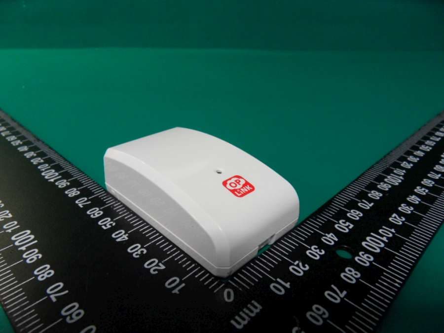
Click to zoom
Application Details
- Equipment Class
- DXX - Part 15 Low Power Communication Device Transmitter
- Date of Grant
- Apr 28, 2014
- Application Purpose
- Original Equipment
- Date of Application
- Apr 27, 2014
- Equipment Note
- Garage Door Sensor
- Frequency Range
- 433.92000000 - 433.92000000
- Country
- China
Documents & Files
Document Text
Text extracted from the exhibit documents filed with the FCC. Open a document above to read the original.
Users Manual
Operation 1. Opening the garage door sensor to change angle of detector will send the status of "Open"(1111 0010 1001 100X) to receiver, and the LED will flash once. 2. Closing the garage door sensor to change angle of detector will send the status of "Close"(1111 0010 1001 101X) to receiver, and the LED will flash once. 3. Normal operation, the LED will not light. 4. The GDS1300 detector equipped with tamper switch. If the cover of detector is removed, the garage door sensor will send an temper alarm report (1111 0010 1001 111X) to the receiver, and the LED will flash once. Federal Communications Commission Statement This equipment has been tested and found to comply with the limits for a Class B digital device, pursuant to Part 15 of the FCC Rules. These limits are designed to provide reasonable protection against harmful interference in a residential installation. This equipment generates, uses and can radiate radio frequency energy and, if not installed and used in accordance with the instruction, may cause harmful interference to radio communications. However, there is no guarantee that interference will not occur in a particular installation. If this equipment does cause harmful interference to radio or television reception, which can be determined by turning the equipment off and on, the user is encouraged to try and correct the interferene by one of the following measures: Reorient or relocate the receiving antenna, Increase the separation between the equipment and receiver, Connect the equipment into and outlet on a circuit different from that to which the receiver is connected. Consult the dealer or an experienced radio/TV technician for help. This device complies with Part 15 of the FCC Rules. Operation is subject to the following two conditions: (1) this device may not cause harmful interference, and (2) this device must accept any interference received, including interference that may cause undersired operation. FCC Caution: Any changes or modifications not expressly approved by the party responsible for compliance could void the user’s authority to operate this equipment. Limited Warranty OPLINK Guarantees that every garage door sensor is free from physical defects in material and workmanship under normal use for one year from the date of purchase. If the product proves defective during this two-year warranty period, OPLINK will replace it free of charge. OPLINK does not issue any refunds. This warranty is extended to the original end user purchase only and is not transferable. This warranty does not apply to : (1) damage to units caused by accident, dropping or abuse in handling, or any negligent use; (2) units which have been subject to unauthorized repair, taken apart, or otherwise modified; (3) units not used in accordance with instruction; (4) damages exceeding the cost of the product; (5) transit damage, initial installation costs, removal cost, or reinstallation cost. For information on addional devices, plesae visit us at www.oplink.com -3- Installation & Operation Manual GDS1300 Garage Door Sensor Introduction Thanks for choosing the OPLINK Garage door sensor of the home security device. This sensor monitors garage door open / closes status and send alarm report signal when angle is changed. Product Description and Specification *** For indoor use only*** Specification: Package Content: Frequency: 433.92MHz Operating Range: Up to 100 feet line of sight Operating Temp.: -15°C~ 60°C (5°F ~140°F) 1pc 1pc 2pc 3pcs 1pc 1pc GDS1300 Sensor Bracket Holder Adhesive tape for detector Screw for bracket CR123A Lithium Battery Installation & Operation manual Status/ Signal (Alarm report) Alarm Type Open Alarm 1111 0010 1001 100X Close Alarm 1111 0010 1001 101X Temper Alarm 1111 0010 1001 111X Low Battery Alarm 1111 0010 1001 110X Heart Beat 1111 0010 1010 001X Installation Notice: If you are installing the entire OPLINK Garage door sensor for the first time, please refer to the installation guide of OPLINK Garage door sensor. 1. Install Battery: Use care when installing the battery. Press the locking tab on the top sensor cover, and then gently pull up the cover. Observe the correct polarity before insert the battery. 2. After insert the battery, the LED will start to flashing, which means the sensor has monitors garage door open / close status and send alarm report signal. 3. Slide back the rear cover and screw fastening with the front cover. 4. Using the adhesive tape or fixing screws to fix the bracket holder with garage detector. For better operation, please install detector on top portion of garage door. -2-
Cover Letter(s)
Specification of Antenna Model No: GDS1300 Antenna Type: Helical Antenna Length Closed: N/A Length Open: 20mm Diameter: 45mm No. of element: N/A Antenna Gain: -10 dB Total Resistance: 1.5Ω Temperature: -20°C ~ 70°C
External Photos
Compliance Certification Services Inc. Report No.:T140403N10 Date of Issue: April 21, 2014 Page A1 / 5 External Photo (GDS1300) Compliance Certification Services Inc. Report No.:T140403N10 Date of Issue: April 21, 2014 Page A2 / 5
ID Label/Location Info
GDS1300 Diagram Label location Label location FCC ID:OS3GDS01
Internal Photos
Compliance Certification Services Inc. Report No.:T140403N10 Date of Issue: April 21, 2014 Page A3 / 5 Internal Photo (GDS1300) Compliance Certification Services Inc. Report No.:T140403N10 Date of Issue: April 21, 2014 Page A4 / 5 Antenna Compliance Certification Services Inc. Report No.:T140403N10 Date of Issue: April 21, 2014 Page A5 / 5
Operational Description
GDS1300 GARAGE DOOR SENSOR Operational Description The GDS1300 GARAGE DOOR SENSOR transmitter is a low powered, fixed unit for remote controlling the home security feature. See the function descriptions in attached. A 3VDC battery powers the transmitter. It is designed to operate on a single fixed frequency at 433.92MHz ± 150 kHz. See the attached block diagram and schematic. There are two triggers the integrated circuit (U2) that produces the digital control signals and will modulate the carrier signal (ASK). SAW Resonator generates the carrier signal / amplifier circuit comprised of X1 and transmitter IC (U1). The modulated output of the RF stage is coupled to the helical antenna. The Antenna is attached on helical antenna permanently around 20 mm. The transmitter is manually operated by the TILT switch (SW4) and TAMPER switch (SW3A) pushed momentarily within 0.2 second and will automatically deactivate send signal to receiver. This feature is incorporated by the U2 internally. All tuning and verification are performed by the manufacture and there are user can make no adjustments.
Test Report
Compliance Certification Services Inc. FCC ID: OS3GDS01 Report No.: T140403N10-RP1 Note: This report shall not be reproduced except in full, without the written approval of Compliance Certification Services Inc. This document may be altered or revised by Compliance Certification Services Inc. personnel only, and shall be noted in the revision section of the document. Page 1/ 28 FCC 47 CFR PART 15 SUBPART C ANSI C63.4: 2009 TEST REPORT For Garage Door Sensor Model : GDS1300 Brand : Oplink Issued to Zhuhai FTZ Oplink Communications, Inc. #29#30 Lianfeng Avenue, Free Trade Zone, Zhuhai City, Guangdong Province, China 519030 Issued by Compliance Certification Services Inc. Tainan Lab. No.8,Jiucengling, Xinhua Dist., Tainan City 712, Taiwan (R.O.C.) TEL: (06) 580-2201 FAX: (06) 580-2202 Issued Date: April 21, 2014 Compliance Certification Services Inc. FCC ID: OS3GDS01 Report No.: T140403N10-RP1 Page 2/32 REVISION HISTORY Rev. Issue Date Revisions Effect Page Revised By 00 April 21, 2014 Initial Issue ALL Eva Lin Compliance Certification Services Inc. FCC ID: OS3GDS01 Report No.: T140403N10 -RP1 Page 3/ 28 TABLE OF CONTENTS 1. TEST RESULT CERTIFICATION .....................................................................................4 2. EUT DESCRIPTION..........................................................................................................5 3. TEST METHODOLOGY....................................................................................................6 3.1 EUT CONFIGURATION .................................................................................................6 3.2 EUT EXERCISE .............................................................................................................6 3.3 GENERAL TEST PROCEDURES ..................................................................................6 3.4 FCC PART 15.205 RESTRICTED BANDS OF OPERATIONS ......................................7 3.5 DESCRIPTION OF TEST MODES .................................................................................7 4. INSTRUMENT CALIBRATION .........................................................................................8 4.1 MEASURING INSTRUMENT CALIBRATION.................................................................8 4.2 MEASUREMENT EQUIPMENT USED...........................................................................8 4.3 MEASUREMENT UNCERTAINTY .................................................................................9 5. FACILITIES AND ACCREDITATIONS ...........................................................................10 5.1 FACILITIES ..................................................................................................................10 5.2 EQUIPMENT ................................................................................................................10 5.3 TABLE OF ACCREDITATIONS AND LISTINGS ..........................................................10 5.4 TABLE OF ACCREDITATIONS AND LISTINGS ..........................................................11 6. SETUP OF EQUIPMENT UNDER TEST ........................................................................12 6.1 SETUP CONFIGURATION OF EUT ............................................................................12 6.2 SUPPORT EQUIPMENT ..............................................................................................12 7. FCC PART 15.231 REQUIREMENTS ............................................................................13 7.1 20 DB BANDWIDTH .....................................................................................................13 7.2 LIMIT OF TRANSMISSION TIME.................................................................................15 7.3 DUTY CYCLE...............................................................................................................17 7.4 CENTRAL FREQUNCY................................................................................................20 7.5 RADIATED EMISSIONS...............................................................................................22 7.6 POWERLINE CONDUCTED EMISSIONS ...................................................................37 8. APPENDIX 1 PHOTOGRAPHS OF TEST SETUP.........................................................38 Compliance Certification Services Inc. FCC ID: OS3GDS01 Report No.: T140403N10 -RP1 Page 4/ 28 1. TEST RESULT CERTIFICATION Product: Garage Door Sensor Model: GDS1300 Brand Name: Oplink Applicant: Zhuhai FTZ Oplink Communications, Inc. #29#30 Lianfeng Avenue, Free Trade Zone, Zhuhai City, Guangdong Province, China 519030 Manufacturer: Vision Automobile Electronics Industrial Co., Ltd. No. 78, Gongye 3rd Rd., Technology Industrial Park, Tainan 70955, Taiwan Tested: April 7, 2014 – April 17, 2014 APPLICABLE STANDARDS STANDARD TEST RESULT FCC 47 CFR Part 15 Subpart C: 2012 ANSI C63.4 : 2009 No non-compliance noted We hereby certify that: The above equipment was tested by Compliance Certification Services Inc. The test data, data evaluation, test procedures, and equipment configurations shown in this report were made in accordance with the procedures given in ANSI C63.4: 2009 and the energy emitted by the sample EUT tested as described in this report is in compliance with conducted and radiated emission limits of FCC Rules Part 15.207, 15.209 and Part 15.231(a). The test results of this report relate only to the tested sample identified in this report. Approved by: Reviewed by: Jeter Wu Assistant Manager Eric Huang Assistant Section Manager Compliance Certification Services Inc. FCC ID: OS3GDS01 Report No.: T140403N10 -RP1 Page 5/ 28 2. EUT DESCRIPTION Product Garage Door Sensor Model Number GDS1300 Brand Name Oplink Received Date April 03, 2014 Frequency Range 433.92 MHz ± 150 kHz Number of Channels 1 Channel Type of Modulation ASK Power Supply 3Vdc (Powered from battery) Antenna Type Helical antenna Gain: -10 dBi Temperature Range -20°C ~ …
Text truncated - open the document above for the full version.
Test Setup Photos
Compliance Certification Services Inc. FCC ID: OS3GDS01 Report No.: T140403N10 -RP1 Page 38/ 28 8. APPENDIX 1 PHOTOGRAPHS OF TEST SETUP Radiated Emission Setup Photo X-axis Compliance Certification Services Inc. FCC ID: OS3GDS01 Report No.: T140403N10 -RP1 Page 39/ 28 Compliance Certification Services Inc. FCC ID: OS3GDS01 Report No.: T140403N10 -RP1 Page 40/ 28 Y-axis Compliance Certification Services Inc. FCC ID: OS3GDS01 Report No.: T140403N10 -RP1 Page 41/ 28 Compliance Certification Services Inc. FCC ID: OS3GDS01 Report No.: T140403N10 -RP1 Page 42/ 28 Z-axis Compliance Certification Services Inc. FCC ID: OS3GDS01 Report No.: T140403N10 -RP1 Page 43/ 28 Compliance Certification Services Inc. FCC ID: OS3GDS01 Report No.: T140403N10 -RP1 Page 44/ 28 RADIATED EMISSION SETUP
Contact Information
Applicant
Lizhi Li(Engineer)
Technical Contact
Compliance Certification Services Inc.Daphne Liang
886-6-580-2201
Taiwan
Non-Technical Contact
Compliance Certification Services Inc.Daphne Liang
886-6-580-2201
Test Firm
Compliance Certification Services Inc.Daphne Liang
Technical Specifications
| # | Rule Parts | Frequency Range | Power Output |
|---|---|---|---|
| 1 | 15C | 433.92 MHz - 433.92 MHz | - |
Other Applications from Zhuhai FTZ Oplink Communications, Inc.
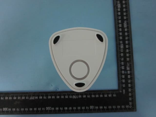
OS3OPU04
Sep 23, 2014Oplink Processing Unit Router
Equipment Class
DXX - Part 15 Low Power Communication Device Transmitter
OS3IPC05
Aug 10, 2014Wireless IP camera
Equipment Class
DTS - Digital Transmission System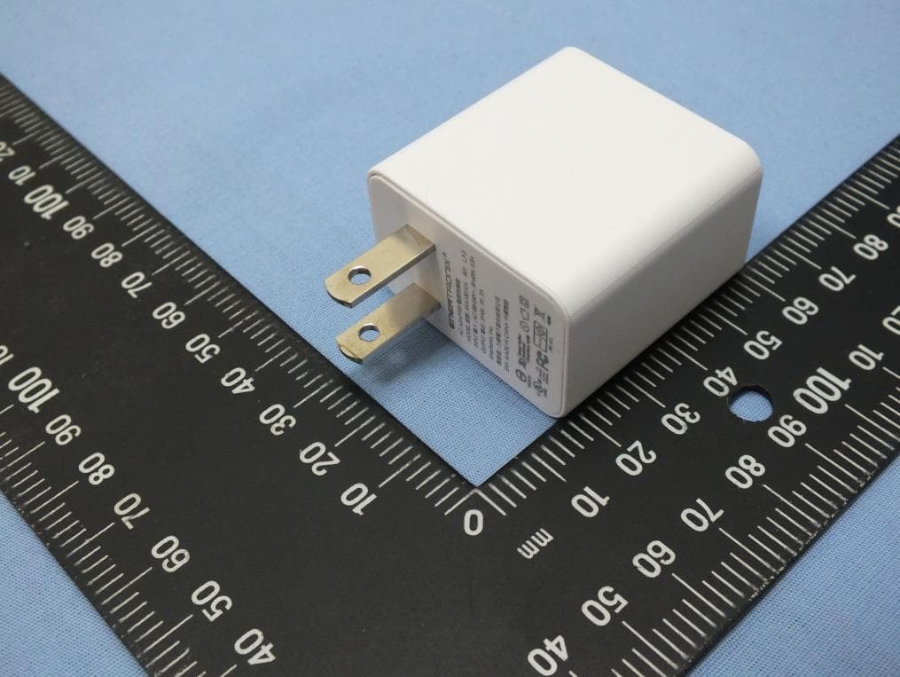
OS3IPC04
May 15, 2014Wireless IP Camera
Equipment Class
DTS - Digital Transmission System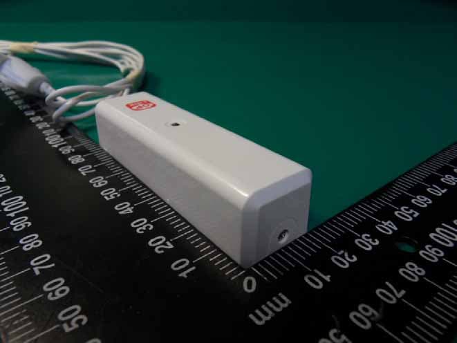
OS3WLS01
Apr 28, 2014Water Leak Sensor
Equipment Class
DXX - Part 15 Low Power Communication Device Transmitter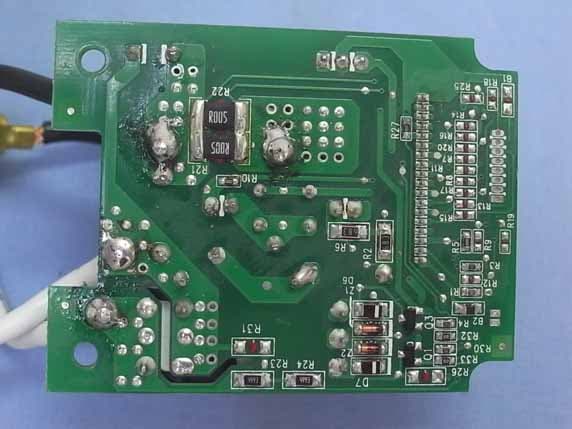
OS3WPS01
Nov 20, 2013WiFi Smart Plug
Equipment Class
DTS - Digital Transmission System