OS3SMH01Wireless Smoke +Heat Semsor
Zhuhai FTZ Oplink Communications, Inc.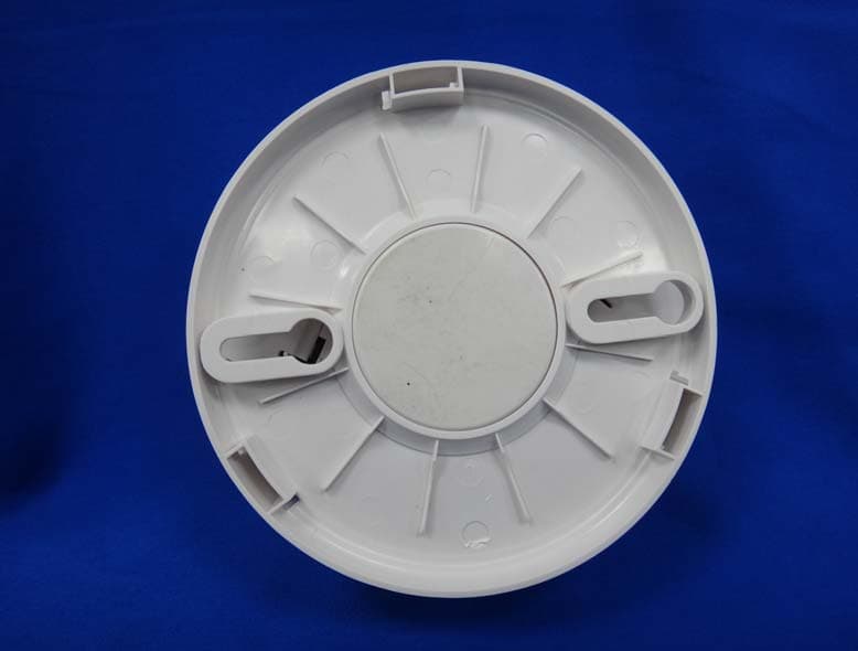
Click to zoom
Application Details
- Equipment Class
- DSC - Part 15 Security/Remote Control Transmitter
- Date of Grant
- Jun 09, 2013
- Application Purpose
- Original Equipment
- Date of Application
- Jun 09, 2013
- Equipment Note
- Wireless Smoke +Heat Semsor
- Frequency Range
- 433.92000000 - 433.92000000
- Country
- China
Documents & Files
Document Text
Text extracted from the exhibit documents filed with the FCC. Open a document above to read the original.
Users Manual
1 ISSUE NO. MSD0360-20120706 REV.A INTRODUCTION Everday’s single station photoelectric smoke detector SD360 series is designed to sense smoke that comes into the alarm chamber. It does not sense gas, or flame. This smoke alarm is designed to give early warning of developing fires by giving off the alarm sounds from its built-in alarm horn. It can provide precious time for you and your family to escape before a fire spreads. However, the smoke alarm makes such pre-warning of fire accident possible, only if the smoke alarm is located, installed, and maintained properly as described in this User's Manual. WARNING: This smoke alarm is designed for use in a single residential unit only, which means that it should be used inside a single family home or apartment. It is not meant to be used in lobbies, hallways, basements, or another apartment in multi-family buildings, unless there are already working alarms in each family unit. Smoke alarms , placed in common areas outside of the individual living unit, such as on porches or in hallways, may not provide early warning to residents. In multi-family buildings, each family living unit should set up its own smoke alarms. WARNING: This alarm is not meant to be used in non-residential buildings. W arehouses, industrial or commercial buildings, and special purpose non-residential buildings require special fire detection and alarm systems. This smoke alarm alone is not a suitable substitute for complete fire detection systems for places where many people live or work, such as hotels or motels. The same is true of dormitories, hospitals, nursing homes or group homes of any kind, even if they were once single family homes. Please refer NFPA 101, the Life Safety Code, NFPA 72A for smoke alarm requirements for fire protection in buildings not defined as “households”. WARNING: This smoke alarm will not alert people who are hard of hearing. It is strongly recommended that the special-purpose smoke alarms, using lights or vibrating devices, should be installed to alert occupants who are hard of hearing. LOCATIONS TO INSTALL YOUR SMOKE ALARM Smoke alarms should be installed in accordance with the NFPA Standard 72 (National Fire Protection Association, Battery march Park, Quincy, MA 02169). For complete coverage in residential units, smoke alarms should be installed in all rooms, halls, storage areas, basements, and attics in each family living unit. Minimum coverage is one alarm on each floor and one in each sleeping area. Here, we have useful tips for you: Ԧ Install a smoke alarm in the hallway outside every separate bedroom area, as shown in Figure 1. Two alarms are required in homes with two bedroom areas, as shown in Figure 2. Ԧ Install a smoke alarm on every floor of a multi-floor home or apartment, as shown in Figure 3. Ԧ Install a minimum of two alarms in any household. Ԧ Install a smoke alarm inside every bedroom. Ԧ Install smoke alarms at both ends of a bedroom hallway if the hallway is more than 40 feet (12 meters) long. Ԧ Install a smoke alarm inside every room where one sleeps with the door partly or completely closed, since smoke could be blocked by the closed door and a hallway alarm may not wake up the sleeper if the door is closed. Ԧ Install basement alarms at the bottom of the basement stairwell. Ԧ Install second-floor alarms at the top of the first-to-second floor stairwell. Be sure no door or other obstruction blocks the path of smoke to the alarm. ԦInstall additional alarms in your living room, dining room, family room, attic, utility and storage rooms. Ԧ Install smoke alarms as close to the center of the ceiling as possible. If this is not practical, put the alarm on the ceiling, no closer than 4 inches (10 cm) from any wall or corner, as shown in Figure 4. Ԧ If ceiling mounting is not possible and wall mounting is permitted by your local and state codes, put wall-mounted alarms between 4 and 6 inches (10 ~ 15 cm) from the ceiling, also see Figure 4. Ԧ If some of your rooms have sloped, peaked, or gabled ceilings, try to mount alarms 3 feet (0.9 meter) measured horizontally from the highest point of the ceiling as shown in Figure 5. Figure 4: RECOMMENDED BEST AND ACCEPTABLE LOCATIONS TO MOUNT SMOKE ALARMS Figure 5: RECOMMENDED LOCATION TO MOUNT SMOKE ALARMS IN ROOMS W ITH SLOPED, GABLED, OR PEAKED CEILING CAUTION (As required by the California State Fire Marshall) “Early warning fire” detection is best achieved by the installation of fire detection equipment in all rooms and areas of the household as follows: (1) A smoke alarm installed in each separate sleeping area (in the vicinity, but outside of the bedrooms), and (2) Heat or smoke alarms in the living rooms, dining rooms, bedrooms, kitchens, hallways, attics, furnace rooms, closets, utility and, storage rooms, basements and attached garages.” For your information, NFPA Standard 72, Section 29 reads as follows: “29.5.1 Smoke alarms shall be installed outside of each separate sleeping area in the immediate vicinity of the bedrooms and on each additional story of the family living unit including basements and excluding crawl spaces and unfinished attics. The provisions of 29.5.1 represent the minimum number of alarms required by this standard. It is recommended that the householder consider the use of additional smoke alarms for increased protection for those areas separated by a door from the areas protected by the required smoke alarms under 29.5.1 above. The recommended additional areas are living room, dining room, bedroom(s), kitchen, attic (finished or unfinished), furnace rooms, utility room, basement, integral or attached garage, and hallways not included in 29.5.1 above. However, the use of additional alarms remains the option of the householder.” W e recommend complete coverage and use of additional smoke alarms. LOCATIONS NOT TO INSTALL YOUR SMOKE ALARMS Nuisance alarms take place when smoke alarms are installed where they will not work properly. To avoid nuisance alarms, do …
Text truncated - open the document above for the full version.
External Photos
Report No.: 135017R-RFUSP04V01 Page : 1 of 10 Attachment 2 : EUT Detailed Photographs (1) EUT Photo (2) EUT Photo Report No.: 135017R-RFUSP04V01 Page : 2 of 10 (3) EUT Photo (4) EUT Photo
ID Label/Location Info
Zhuhai FTZ Oplink Communications, Inc. FCC ID.: OS3SMH01 #29, #30 Lianfeng Avenue, Free Trade Zone, Zhuhai, Guangdong Province, China 519030 Tel : (86 756) 8819682 The FCC ID Label will be placed on the equipment as shown in the photograph below.
Internal Photos
Report No.: 135017R-RFUSP04V01 Page : 3 of 10 (5) EUT Photo (6) EUT Photo Report No.: 135017R-RFUSP04V01 Page : 4 of 10 (7) EUT Photo (8) EUT Photo Report No.: 135017R-RFUSP04V01 Page : 5 of 10 (9) EUT Photo (10) EUT Photo Report No.: 135017R-RFUSP04V01 Page : 6 of 10 (11) EUT Photo (12) EUT Photo Report No.: 135017R-RFUSP04V01 Page : 7 of 10 (13) EUT Photo (14) EUT Photo Report No.: 135017R-RFUSP04V01 Page : 8 of 10 (15) EUT Photo (16) EUT Photo Report No.: 135017R-RFUSP04V01 Page : 9 of 10 (17) EUT Photo (18) EUT Photo Report No.: 135017R-RFUSP04V01 Page : 10 of 10 (19) EUT Photo
Test Report
Report No:135017R-RFUSP04V01 Page: 1 of 24 FCC Test Report Product Name Wireless Smoke +Heat Sensor Model No. SMH1300 FCC ID. OS3SMH01 Applicant Zhuhai FTZ Oplink Communications, Inc. Address #29, #30 Lianfeng Avenue, Free Trade Zone, Zhuhai, Guangdong Province, China 519030 Date of Receipt Apr. 26, 2013 Issued Date May 07, 2013 Report No. 135017R-RFUSP04V01 Report Version V1.0 The test results relate only to the samples tested. The test report shall not be reproduced except in full without the written approval of QuieTek Corporation. This report must not be used to claim product endorsement by NVLAP any agency of the U.S. Government Report No:135017R-RFUSP04V01 Page: 2 of 24 Test Report Certification Issued Date : May 07, 2013 Report No. : 135017R-RFUSP04V01 Product Name Wireless Smoke + Heat Sensor Applicant Zhuhai FTZ Oplink Communications, Inc. Address #29, #30 Lianfeng Avenue, Free Trade Zone, Zhuhai, Guangdong Province, China 519030 Manufacturer EVERDAY Technology Co., Ltd. Model No. SMH1300 FCC ID. OS3SMH01 EUT Rated Voltage DC 3V(Power by Battery) EUT Test Voltage DC 3V(Power by Battery) Trade Name N/A Applicable Standard FCC CFR Title 47 Part 15 Subpart C: 2012 ANSI C63.4: 2003, ANSI C63.10: 2009 Test Result Complied Test results relate only to the samples tested. The test report shall not be reproduced except in full without the written approval of QuieTek Corporation. This report must not be used to claim product endorsement by NVLAP any agency of the U.S. Government Documented By : (Senior Engineering Adm. Specialist / Anita Chou) Tested By : ( Engineer / Nowal Kuo ) Approved By : ( Manager / Vincent Lin) Report No:135017R-RFUSP04V01 Page: 3 of 24 TABLE OF CONTENTS Description Page 1. General Information ...................................................................................................................4 1.1. EUT Description............................................................................................................................4 1.2. Operation Description ...................................................................................................................5 1.3. Tested System Details....................................................................................................................6 1.4. Configuration of tested System .....................................................................................................6 1.5. EUT Exercise Software .................................................................................................................6 1.6. Test Facility ...................................................................................................................................7 2. Conducted Emission....................................................................................................................8 2.1. Test Equipment..............................................................................................................................8 2.2. Test Setup ......................................................................................................................................8 2.3. Limits ............................................................................................................................................9 2.4. Test Procedure ...............................................................................................................................9 2.5. Test Specification ..........................................................................................................................9 2.6. Uncertainty ....................................................................................................................................9 2.7. Test Result ...................................................................................................................................10 3. Radiated Emission ..................................................................................................................... 11 3.1. Test Equipment............................................................................................................................11 3.2. Test Setup ....................................................................................................................................12 3.3. Limits ..........................................................................................................................................13 3.4. Test Procedure .............................................................................................................................14 3.5. Test Specification ........................................................................................................................14 3.6. Uncertainty ..................................................................................................................................14 3.7. Test Result ...................................................................................................................................15 4. Transmit time.............................................................................................................................21 4.1. Test Equipment............................................................................................................................21 4.2. Test Setup ....................................................................................................................................21 4.3. Limits ..........................................................................................................................................21 4.4. Test Specification ........................................................................................................................21 4.5. Uncertainty ..................................................................................................................................21 …
Text truncated - open the document above for the full version.
Test Setup Photos
Report No.: 135017R-RFUSP04V01 Page : 1 of 2 Attachment 1: EUT Test Setup Photographs Front View of Radiated Test Back View of Radiated Test Report No.: 135017R-RFUSP04V01 Page : 2 of 2 Front View of Radiated Test (Horn) Back View of Radiated Test (Horn)
Contact Information
Applicant
Lizhi Li(Engineer)
Technical Contact
QuieTek CorporationSabina Chen
[email protected]886-2-8601-3788
No. 5-22, Rueishu Keng, Linkou Dist., · New Taipei City · Taiwan
Test Firm
DEKRA Testing and Certification Co., Ltd.Sky Hsu
Technical Specifications
| # | Rule Parts | Frequency Range | Power Output |
|---|---|---|---|
| 1 | 15.231 | 433.92 MHz - 433.92 MHz | - |
Other Applications from Zhuhai FTZ Oplink Communications, Inc.
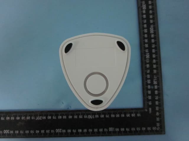
OS3OPU04
Sep 23, 2014Oplink Processing Unit Router
Equipment Class
DXX - Part 15 Low Power Communication Device Transmitter
OS3IPC05
Aug 10, 2014Wireless IP camera
Equipment Class
DTS - Digital Transmission System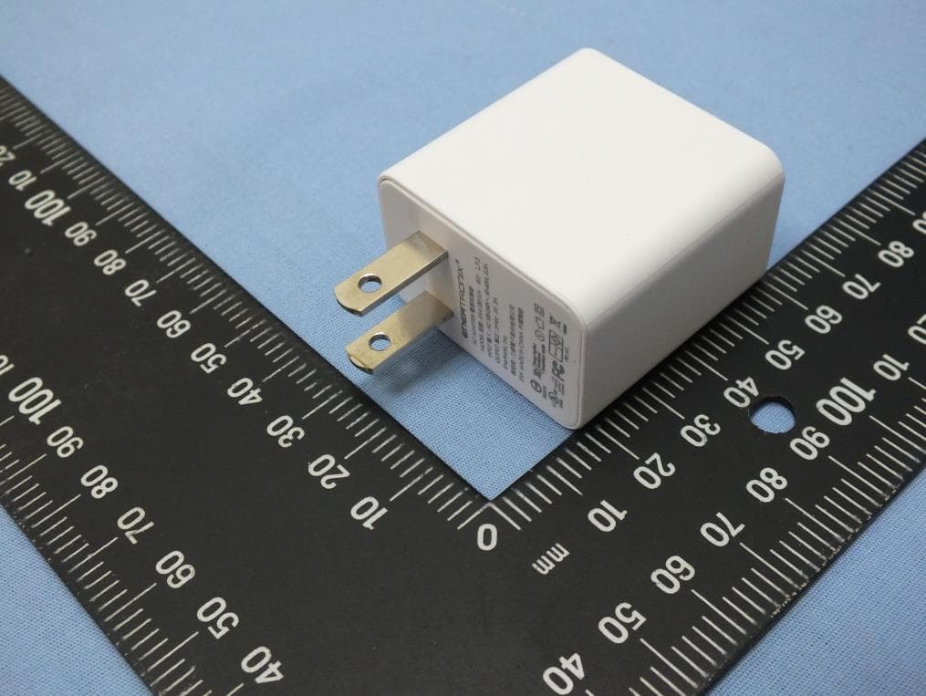
OS3IPC04
May 15, 2014Wireless IP Camera
Equipment Class
DTS - Digital Transmission System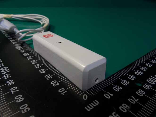
OS3WLS01
Apr 28, 2014Water Leak Sensor
Equipment Class
DXX - Part 15 Low Power Communication Device Transmitter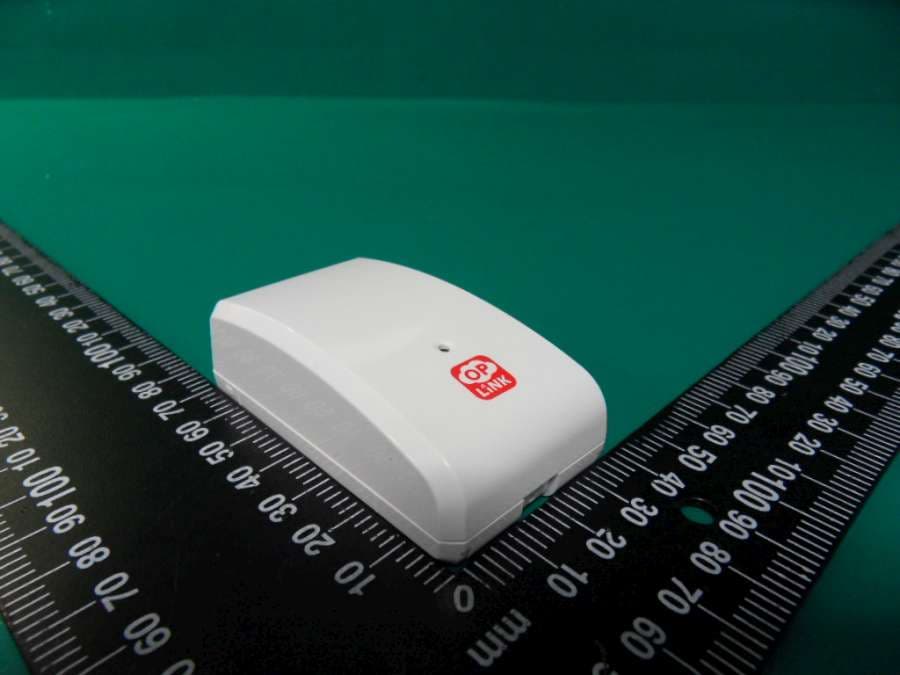
OS3GDS01
Apr 28, 2014Garage Door Sensor
Equipment Class
DXX - Part 15 Low Power Communication Device Transmitter