OS3SOK01Shock Sensor
Zhuhai FTZ Oplink Communications, Inc.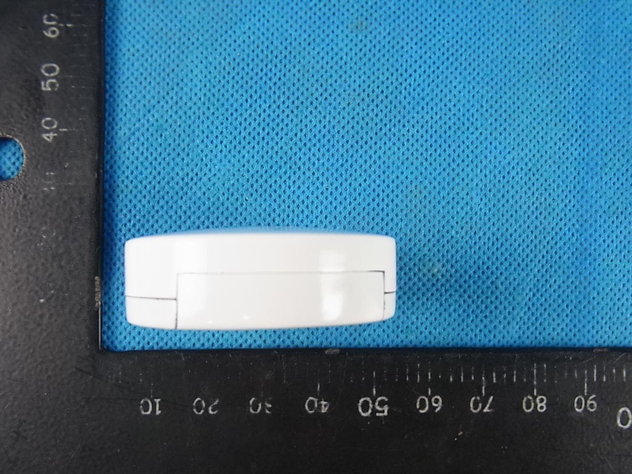
Click to zoom
Application Details
- Equipment Class
- DSC - Part 15 Security/Remote Control Transmitter
- Date of Grant
- Mar 06, 2013
- Application Purpose
- Original Equipment
- Date of Application
- Mar 06, 2013
- Equipment Note
- Shock Sensor
- Frequency Range
- 433.92000000 - 433.92000000
- Country
- China
Documents & Files
Document Text
Text extracted from the exhibit documents filed with the FCC. Open a document above to read the original.
Users Manual
Oplink Communications User Guide I. Product Introduction Shock sensor is a 433MHz wireless remote control. When the monitor device shock exceed 1 G, and it will send arm/disarm/panic signal to the system. Stand by Montor device Was strongly impact Vibration strength more than trigger threshold Transmit RF singal Receiver Y N Oplink Communications II. Installation (1) Usage scenario: • Indoors or windows and away from direct sunlight. • Away from extreme temperature sources and large metal objects. (2) Operation: • push the locker of Remote control. • Insert the battery noting the polarity (A23 battery); Oplink Communications FCC Statement This device complies with part 15 of the FCC Rules. Operation is subject to the following two conditions: (1) This device may not cause harmful interference, and (2) This device must accept any interference received, including interference that may cause undesired operation. Warning: Changes or modifications to this unit not expressly approved by the party responsible for compliance could void the user’s authority to operate the equipment. NOTE: This equipment has been tested and found to comply with the limits for a Class B digital device, pursuant to Part 15 of the FCC Rules. These limits are designed to provide reasonable protection against harmful interference in a residential installation. This equipment generates uses and can radiate radio frequency energy and, if not installed and used in accordance with the instructions, may cause harmful interference to radio communications. However, there is no guarantee that interference will not occur in a particular installation. If this equipment does cause harmful interference to radio or television reception, which can be determined by turning the equipment off and on, the user is encouraged to try to correct the interference by one or more of the following measures: Reorient or relocate the receiving antenna. Increase the separation between the equipment and receiver. Connect the equipment into an outlet on a circuit different from that to which the receiver is connected. Consult the dealer or an experienced radio/TV technician for help. Oplink Communications Europe – EU Declaration of Conformity This device complies with the essential requirements of the R&TTE Directive 1999/5/EC. The following test methods have been applied in order to prove presumption of conformity with the essential requirements of the R&TTE Directive 1999/5/EC: - EN 60950-1: 2006+A11:2009 +A1:2010+A12:2011 - EN 300 220-1 V2. 4.1 (2012-05) - EN 300 220-2 V2. 4.1 (2012-05) - EN 301 489-1 V1.9.2 (2011-09) - EN 301 489-3 V1.4.1 (2002-08) - EN 62479: 2010 - In Italy the end-user should apply for a license at the national spectrum authorities in order to obtain authorization to use the device for setting up outdoor radio links and/or for supplying public access to telecommunications and/or network services. - This device may not be used for setting up outdoor radio links in France and in some areas the RF output power may be limited to 10 mW EIRP in the frequency range of 2454 – 2483.5 MHz. For detailed information the enduser should contact the national spectrum authority in France. DEVICE DISPOSAL 1. Dispose of batteries properly and in accordance with applicable local laws. Do not burn batteries. They may explode. 2. Recycle electrical products. Check with your local authority for recycling information. Do not dispose electrical products with household waste. OPERATING AND STORAGE - Operating and storage: 0º to 50º C
Users Manual
Oplink Communications User Guide I. Product Introduction Shock sensor is a 433MHz wireless remote control. When the monitor device shock exceed 1 G, and it will send arm signal to the system. Stand by Montor device Was strongly impact Vibration strength more than trigger threshold Transmit RF singal Receiver Y N Oplink Communications II. Installation (1) Usage scenario: • Indoors or windows and away from direct sunlight. • Away from extreme temperature sources and large metal objects. (2) Operation: • push the locker of Remote control. • Insert the battery noting the polarity (A23 battery); Oplink Communications FCC Statement This device complies with part 15 of the FCC Rules. Operation is subject to the following two conditions: (1) This device may not cause harmful interference, and (2) This device must accept any interference received, including interference that may cause undesired operation. Warning: Changes or modifications to this unit not expressly approved by the party responsible for compliance could void the user’s authority to operate the equipment. NOTE: This equipment has been tested and found to comply with the limits for a Class B digital device, pursuant to Part 15 of the FCC Rules. These limits are designed to provide reasonable protection against harmful interference in a residential installation. This equipment generates uses and can radiate radio frequency energy and, if not installed and used in accordance with the instructions, may cause harmful interference to radio communications. However, there is no guarantee that interference will not occur in a particular installation. If this equipment does cause harmful interference to radio or television reception, which can be determined by turning the equipment off and on, the user is encouraged to try to correct the interference by one or more of the following measures: Reorient or relocate the receiving antenna. Increase the separation between the equipment and receiver. Connect the equipment into an outlet on a circuit different from that to which the receiver is connected. Consult the dealer or an experienced radio/TV technician for help.
Cover Letter(s)
Authorization Letter We, (the approval holder) Company name Zhuhai FTZ Oplink Communications, Inc. Addresss #29, #30 Lianfeng Avenue, Free Trade Zone, City Zhuhai City, Guangdong Province Country China declare that the following representative (agent): Name (person) Bovey.yang Company name NTEK Testing Technology Co., Ltd. Addresss 1/F, Building E, Fenda Science Park Sanwei Community, Xixiang Street, Baoan District City Shenzhen Country China to act on our behalf on all matters concerning the application and documents submitted to PHOENIX TEST-LAB for product certification below Product Description OP Guard Unit Type or Model(s) Shock sensor Tradename or Brand(s) Oplink Attestation: City and Country: Date: Name: (this must be a person) Function: Signature: (or official company stamp) Zhuhai City, Guangdong Province,China 2013-1-9 Lizhi Li Engineer
Cover Letter(s)
FCC Confidentiality Request To the FCC and FCC TCB handling this application for certification Pursuant to 47 CFR Section 0.459(a) & (b), we, (the applicant / grantee) Company name Zhuhai FTZ Oplink Communications, Inc. Addresss #29, #30 Lianfeng Avenue, Free Trade Zone, City Zhuhai City, Guangdong Province Country China request non-disclosure and confidential treatment for our certification under: Grantee Code Product Number FCC ID: OS3 SOK01 of the following materials submitted within this certification application: (please cross what is applicable, or add other documents) X Operational Description X Block Diagrams X Schematics Diagrams Above materials contain secrets, proprietary and technical information, which would customarily be guarded from competitors under 47 CFR, section 0.457(d)(2). Disclosure or publication or any portion of this company confidential material to other parties could cause substantial competitive harm and provide unjustified benefits for competitors. We understand that pursuant to 47 CFR section 0.457(d)(1)(ii) disclosure of the applicant and all accompanying documentation will not be made before the date of the grant. Attestation: City and Country: Date: Name: (this must be a person) Function: Signature: (or official company stamp) Zhuhai City, Guangdong Province,China 2013-01-09 Lizhi Li Engineer
External Photos
APPENDIX-PHOTOGRAPHS OF EUT CONSTRUCTIONAL DETAILS Photo 1 Photo 2 Photo 3 Photo 4 Photo 5 Photo 6
ID Label/Location Info
Label
Internal Photos
Photo 7 Photo 8 Photo 9 Photo 10
Test Report
FCC RADIO TEST REPORT FCC ID: OS3SOK01 Product: Shock sensor Trade Name: OPLINK Model Name: SOK1300 Serial Model: N/A Report No.: NTEK-2013NT0225042F Prepared for Zhuhai FTZ Oplink Communications, Inc. #29, #30 Lianfeng Avenue, Free Trade Zone, Zhuhai City, Guangdong Province, China 519030 Prepared by NTEK Testing Technology Co., Ltd. 1/F, Building E, Fenda Science Park, Sanwei Community,Xixiang Street Bao’an District, Shenzhen P.R. China Tel.: +86-0755-61156588 Fax.: +86-0755-61156599 Website:www.ntek.org.cn Page 2 of 27 Report No.: NTEK-2013NT0225042F ` TEST RESULT CERTIFICATION Applicant’s name ................. : Zhuhai FTZ Oplink Communications, Inc. Address ................................. : #29, #30 Lianfeng Avenue, Free Trade Zone, Zhuhai City, Guangdong Province, China 519030 Product description Product name............................ : Shock sensor Model and/or type reference : SOK1300 Serial Model: N/A Rating(s) ................................ : DC 3V Standards ............................. : FCC Part15.231 Test procedure ............................... : ANSI C63.4-2003 This device described above has been tested by NTEK, and the test results show that the equipment under test (EUT) is in compliance with the FCC requirements. And it is applicable only to the tested sample identified in the report. This report shall not be reproduced except in full, without the written approval of NTEK, this document may be altered or revised by NTEK, personal only, and shall be noted in the revision of the document. Date of Test ........................................... : Date (s) of performance of tests ............. : 15 Feb. 2013 ~21 Feb. 2013 Date of Issue .......................................... : 22 Feb. 2013 Test Result.............................................. : Pass Testing Engineer : (Apple Huang) Technical Manager : (Tom Zhang) Authorized Signatory : (Bovey Yang) Page 3 of 27 Report No.: NTEK-2013NT0225042F ` Table of Contents Page 1 . SUMMARY OF TEST RESULTS 4 1.1 TEST FACILITY 5 1.2 MEASUREMENT UNCERTAINTY 5 2 . GENERAL INFORMATION 6 2.1 GENERAL DESCRIPTION OF EUT 6 2.2 DESCRIPTION OF TEST MODES 7 2.3 BLOCK DIGRAM SHOWING THE CONFIGURATION OF SYSTEM TESTED 8 2.4 DESCRIPTION OF SUPPORT UNITS(CONDUCTED MODE) 9 2.5 EQUIPMENTS LIST FOR ALL TEST ITEMS 10 3 . ANTENNA REQUIREMENT 11 3.1 STANDARD REQUIREMENT 11 3.2 EUT ANTENNA 11 3.3 CONDUCTED EMISSION MEASUREMENT 12 3.3.1 POWER LINE CONDUCTED EMISSION LIMITS 12 3.3.2 TEST PROCEDURE 13 3.3.3 DEVIATION FROM TEST STANDARD 13 3.3.4 TEST SETUP 13 3.2.5 TEST RESULT 14 3.4 RADIATED EMISSION MEASUREMENT 15 3.4.1 RADIATED EMISSION LIMITS 15 3.4.2 TEST PROCEDURE 16 3.4.3 DEVIATION FROM TEST STANDARD 16 3.4.4 TEST SETUP 17 3.4.5 TEST RESULTS (BLOW 30MHZ) 19 3.4.6 TEST RESULTS (BETWEEN 30 – 1000 MHZ) 20 4 . BANDWIDTH TEST 23 4.1 TEST PROCEDURE 23 4.2 DEVIATION FROM STANDARD 23 4.3 TEST SETUP 23 4.4 TEST RESULTS 24 5 . TRANSMITTER TIMEOUT 25 5.1 REQUIREMENTS 25 6 . EUT TEST PHOTO 27 APPENDIX-PHOTOGRAPHS OF EUT CONSTRUCTIONAL DETAILS Page 4 of 27 Report No.: NTEK-2013NT0225042F ` 1. SUMMARY OF TEST RESULTS Test procedures according to the technical standards: FCC Part15, Subpart C (15.231) Standard Section Test Item Judgment Remark 15.207 Conducted Emission N/A Note(1) 15.203 Antenna Requirement Pass 15.231 Radiated Spurious Emission Pass 15.231 Occupied Bandwidth Pass 15.231 Transmitter Timeout Pass NOTE: (1) ” N/A” denotes test is not applicable in this Test Report. Page 5 of 27 Report No.: NTEK-2013NT0225042F ` 1.1 TEST FACILITY NTEK Testing Technology Co., Ltd Add. : 1/F, Building E, Fenda Science Park, Sanwei Community, Xixiang Street, Bao’an District, Shenzhen P.R. China. FCC Registration No.:238937; IC Registration No.:9270A-1 CNAS Registration No.:L5516 1.2 MEASUREMENT UNCERTAINTY The reported uncertainty of measurement y ± U,where expended uncertainty U is based on a standard uncertainty multiplied by a coverage factor of k=2,providing a level of confidence of approximately 95 %。 No. Item Uncertainty 1 Conducted Emission Test ±1.38dB 2 RF power,conducted ±0.16dB 3 Spurious emissions,conducted ±0.21dB 4 All emissions,radiated(<1G) ±4.68dB 5 All emissions,radiated(>1G) ±4.89dB 6 Temperature ±0.5°C 7 Humidity ±2% Page 6 of 27 Report No.: NTEK-2013NT0225042F ` 2. GENERAL INFORMATION 2.1 GENERAL DESCRIPTION OF EUT Equipment Shock sensor Trade Name OPLINK Model Name SOK1300 Serial Model N/A Model Difference N/A Product Description The EUT is a Shock sensor Product Type Low Power Communication Device Transmitter Operation Frequency: 433.92MHz Modulation Type: ASK Number Of Channel 1CH. Antenna Designation: Built-in antenna Antenna Gain(Peak) 0.25 dBi Output Power: 73.40 dBuV/m (AV Max.) More details of EUT technical specification, please refer to the User's Manual. Channel List N/A Adapter N/A Battery DC 3.0V Note: 1. For a more detailed features description, please refer to the manufacturer’s specifications or the User's Manual. 2. Table for Filed Antenna Ant . Brand Model Name Antenna Type Connector Gain (dBi) NOTE 1 N/A N/A Built-in Antenna NA 0.25 Antenna Page 7 of 27 Report No.: NTEK-2013NT0225042F ` 2.2 DESCRIPTION OF TEST MODES To investigate the maximum EMI emission characteristics generates from EUT, the test system was pre-scanning tested base on the consideration of following EUT operation mode or test configuration mode which possible have effect on EMI emission level. Each of these EUT operation mode(s) or test configuration mode(s) mentioned above was evaluated respectively. Pretest Mode Description Mode 1 TX For Conducted Emission Final Test Mode Description Mode 1 N/A For Radiated Emission Final Test Mode Description Mode 1 TX Note: (1) The EUT use new battery. (2) The EUT is set to Continuous emission by short sensor. Page 8 of 27 Report No.: NTEK-2013NT0225042F ` 2.3 BLOCK DIGRAM SHOWING THE CONFIGURATION OF SYSTEM TESTED Radiated Spurious Emission Test E-1 EUT Page 9 of 27 Report No.: NTEK-2013NT0225042F ` 2.4 DESCRIPT…
Text truncated - open the document above for the full version.
Test Setup Photos
Page 26 of 26 Report No.: NTEK-2013NT0225042F ` 6. EUT TEST PHOTO Radiated Measurement Photos
Contact Information
Applicant
Lizhi Li(Engineer)
Test Firm
Shenzhen NTEK Testing Technology Co., Ltd.Jason Chen
Technical Specifications
| # | Rule Parts | Frequency Range | Power Output |
|---|---|---|---|
| 1 | 15.231 | 433.92 MHz - 433.92 MHz | - |
Other Applications from Zhuhai FTZ Oplink Communications, Inc.
OS3OPU04
Sep 23, 2014Oplink Processing Unit Router
Equipment Class
DXX - Part 15 Low Power Communication Device Transmitter
OS3IPC05
Aug 10, 2014Wireless IP camera
Equipment Class
DTS - Digital Transmission System
OS3IPC04
May 15, 2014Wireless IP Camera
Equipment Class
DTS - Digital Transmission System
OS3WLS01
Apr 28, 2014Water Leak Sensor
Equipment Class
DXX - Part 15 Low Power Communication Device Transmitter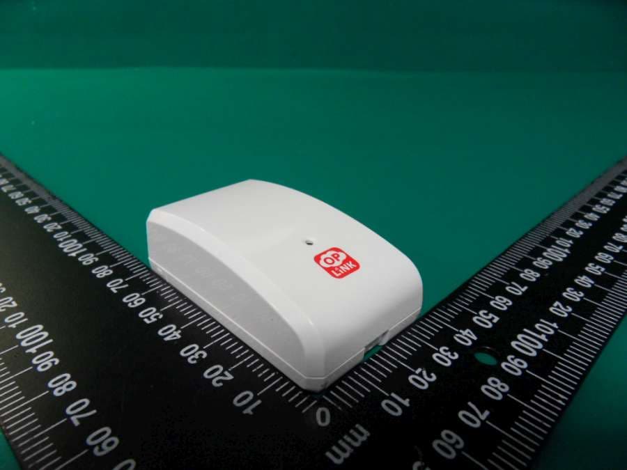
OS3GDS01
Apr 28, 2014Garage Door Sensor
Equipment Class
DXX - Part 15 Low Power Communication Device Transmitter