P2G-RDR-ICLDoor Lock with Proximity Reader Transmitter
Schlage Electronic Security
Click to zoom
Application Details
- Equipment Class
- DXX - Part 15 Low Power Communication Device Transmitter
- Date of Grant
- Feb 06, 2005
- Application Purpose
- Original Equipment
- Date of Application
- Feb 06, 2005
- Equipment Note
- Door Lock with Proximity Reader Transmitter
- Frequency Range
- 13.55300000 - 13.56700000
- Company
- Schlage Electronic Security
- Country
- United States
Documents & Files
Document Text
Text extracted from the exhibit documents filed with the FCC. Open a document above to read the original.
Users Manual
INSTALLATION INSTRUCTIONS MODULAR INTEGRATED READER LOCK (MIRL) STANDARD CYLINDRICAL ( ( i i n n c c l l u u d d i i n n g g d d r r i i l l l l j j i i g g & & s s c c a a r r / / p p u u s s h h p p l l a a t t e e i i n n s s t t r r u u c c t t i i o o n n s s ) ) The most current version of this document is available for download at: www.recognition-source.com 3820 Stern Avenue St. Charles, IL 60174 Phone: 630-762-4450 Fax: 630-762-4455 www.recognition-source.com P/N: M053-021-006 3820 Stern Avenue St. Charles, IL 60174 (630) 762-4450 P/N: M053-021-006 (630) 762-4444 fax Page 2 of 42 3820 Stern Avenue St Charles, IL 60174 (630) 762-4450 (630) 762-4455 Fax World Wide Web http://www.recognition-source.com Copyright © 2003-2004 Recognition Source, LLC, all rights reserved. No part of this document can be reproduced, transmitted, or transcribed in any form by electrical, mechanical, optical, manual, or otherwise without the prior written consent of Recognition Source. Recognition Source reserves the right to alter or revise the content of this document as needed to support future product revisions, without obligation to notify any persons of specific changes. The use of trademarks, trade names, or other product identification is solely for reference purposes. All other product brand names are trademarks or registered trademarks of their respective holders. Recognition Source believes the information in this document to be accurate and reliable. Recognition Source does not guarantee results from the use of this information. Recognition Source assumes no responsibility, obligation, or liability for the information presented in this document. 3820 Stern Avenue St. Charles, IL 60174 (630) 762-4450 P/N: M053-021-006 (630) 762-4444 fax Page 3 of 42 INSTALLATION INSTRUCTIONS Wyreless Access ™ MIRL Standard Cylindrical NOTE: These instructions are for installing the Modular Integrated Reader Lock (MIRL) Standard Cylindrical, a component of a Wyreless Access System. After completing this installation refer to the Configuring and Operating the Wyreless Access System manual. Table of Contents 1. Wyreless Access TM System Components ..................................................................................................... 4 1.1 Overview ............................................................................................................................................. 4 1.2 MIRL Standard Cylindrical Components & Sales Models ..................................................................... 5 2. Installing the MIRL Standard Cylindrical ................................................................................................. 7 2.1 Tools Required..................................................................................................................................... 7 2.2 Optional Installation Aids..................................................................................................................... 7 2.3 Determining the Best WPIM and MIRL Locations................................................................................ 8 2.4 Door Preparation .................................................................................................................................. 8 2.5 Marking Holes for Drilling ................................................................................................................... 9 2.6 Drilling Holes .................................................................................................................................... 20 2.7 Mortising for Latch ............................................................................................................................ 20 2.8 Installing the Optional Door Position Switch ...................................................................................... 21 2.9 Mounting Transceiver ........................................................................................................................ 22 2.10 Connecting Door Position Switch Wires ............................................................................................. 25 2.11 Mounting Reader ............................................................................................................................... 26 2.12 Adjusting Lockset to Door Thickness ................................................................................................. 30 2.13 Placing the Lock Chassis into the Chassis Hole and Then Engaging the Retractor in Latch .................. 32 2.14 Connecting & Dressing the Motor, Request to Exit, & Ground Wires.................................................. 33 2.15 Installing the Inside Rose Assembly & Cover .....................................................................................34 2.16 Installing the Inside Lever .................................................................................................................. 34 2.17 Installing Strike Plate ......................................................................................................................... 34 2.18 Installing the Optional Door Position Magnet ..................................................................................... 36 2.19 Install the Battery Pack & Transceiver Cover...................................................................................... 37 3. Troubleshooting ........................................................................................................................................ 39 4. Contacting Recognition Source................................................................................................................. 40 5. FCC/UL Compliance & Warnings............................................................................................................ 41 5.1 FCC Compliance.................................................................................................................…
Text truncated - open the document above for the full version.
Cover Letter(s)
www.HIDCorp.com 9292 Jeronimo Road • Irvine, CA 92618-1905 • Phone (949) 598-1600 Fax (949) 598-1680 (Administration) • Fax (949) 598-1690 (Customer Service) • Fax (949) 598-1692 (Manufacturing & Purchasing) An ASSA ABLOY Group company Request that submitted material be withheld from Public Inspection Pursuant to 47 CFR 0.457(d) and 0.459 Products: 31xxA iCLASS OEM Module Family It is requested that the following material be withheld from public inspection: Description of the iCLASS OEM Module, Circuit Functions, how the device operates, Ground System, and Antenna Block Diagram Schematic These materials are considered HID Corporation Proprietary and Confidential. Revealing the fundamental design for the product to the public, the OEM, and our competition would put us at a competitive disadvantage. We feel we have a product cost/design advantage over our competition with our iCLASS OEM Module family and therefore ask that the above-specified materials be withheld from public and OEM inspection. Frank de Vall Sr. Engineering Manager-Compliance HID Corporation Assa Abloy ITG Research and Development Center 11674 N. Huron Street Denver, CO 80234
External Photos
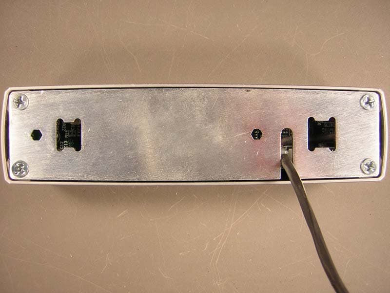
Authorized Agent: Radiometrics Midwest Corporation (815) 293-0772 – [email protected] External EUT Photographs FCC ID: P2G-RDR-ICL Reader Side of installation Authorized Agent: Radiometrics Midwest Corporation (815) 293-0772 – [email protected] Transceiver Side of installation
ID Label/Location Info
Authorized Agent: Radiometrics Midwest Cor poration (815) 293-0772 – [email protected] ID Label/Location FCC ID: P2G-RDR-ICL Dawing and details of FCC label: Radiometrics Midwest Corporation (815) 293-0772 – [email protected] Location of label on EUT:
Internal Photos
Authorized Agent: Radiometrics Midwest Corporation (815) 293-0772 – [email protected] Internal EUT Photographs FCC ID: P2G-RDR-ICL 13.56 MHz card reader with cover off Reader Installed in enclosure Authorized Agent: Radiometrics Midwest Corporation (815) 293-0772 – [email protected] 13.56 MHz card reader PCB 13.56 MHz card reader PCB Authorized Agent: Radiometrics Midwest Corporation (815) 293-0772 – [email protected] 13.56 MHz Card reader Antenna 13.56 MHz Card reader Antenna Authorized Agent: Radiometrics Midwest Corporation (815) 293-0772 – [email protected] Interface PCB Interface PCB Authorized Agent: Radiometrics Midwest Corporation (815) 293-0772 – [email protected] Inside of Cover Enclosure of reader Authorized Agent: Radiometrics Midwest Corporation (815) 293-0772 – [email protected] 902-928 MHz transceiver (previously approved)
Test Report
Radiometrics Midwest Corporation (815) 293-0772 – www.radiomet.com Page 1 of 11 Electromagnetic Compatibility Test Report Tests Performed on a Locknetics Security Engineering iClass Reader Series, Card Reader Radiometrics Document RP-5404 Product Detail: FCC ID: P2G-RDR-ICL Equipment type: DSR; Security/remote Control Transceiver Test Standards: US CFR Title 47, Chapter I, FCC Part 15 Subpart C FCC Part 15 CFR Title 47: 2004 This report concerns: Original Grant for Certification FCC Part 15.225 Tests Performed For: Test Facility: Locknetics Security Engineering 575 Birch St. Forestville, CT 06011-9337 Radiometrics Midwest Corporation 12 East Devonwood Romeoville, IL 60446 Phone: (815) 293-0772 e-mail: [email protected] Test Date(s): (Month-Day-Year) 10/26 & 11/5/04 Document RP-5404 Revisions: Rev. Issue Date Affected Pages Revised By Authorized Signature for Revision 0 November 8, 2004 1 November 10, 2004 1, 6 & 9 Joseph Strzelecki RADIOMETRICS MIDWEST CORPORATION - EMC Test Report Testing of the Locknetics Security Engineering, iClass Reader Series, Card Reader RP-5404 Rev. 0 Page 2 of 11 Table of Contents 1 ADMINISTRATIVE DATA ................................................................................................................... 3 2 TEST SUMMARY AND RESULTS .....................................................................................................3 3 EQUIPMENT UNDER TEST (EUT) DETAILS .................................................................................... 3 3.1 EUT Description ........................................................................................................................... 3 3.1.1 FCC Section 15.203 Antenna Requirements......................................................................... 3 3.2 Related Submittals ....................................................................................................................... 4 4 TESTED SYSTEM DETAILS .............................................................................................................. 4 4.1 Tested System Configuration ....................................................................................................... 4 4.2 Special Accessories ..................................................................................................................... 4 4.3 Equipment Modifications .............................................................................................................. 4 5 TEST SPECIFICATIONS AND RELATED DOCUMENTS.................................................................. 4 6 RADIOMETRICS’ TEST FACILITIES .................................................................................................5 7 DEVIATIONS AND EXCLUSIONS FROM THE TEST SPECIFICATIONS......................................... 5 8 CERTIFICATION ................................................................................................................................ 5 9 TEST EQUIPMENT TABLE ................................................................................................................ 6 10 TEST SECTIONS ............................................................................................................................. 6 10.1 Radiated RF Emissions .............................................................................................................. 6 10.1.1 Field Strength Calculation.................................................................................................... 7 10.1.2 Radiated Emissions Test Results ........................................................................................ 7 10.2 Magnetic Field Measurements and Decay Factor Calculations ................................................. 8 10.2.1 Magnetic Field Radiated Emissions Results (0.15 to 30 MHz) ............................................ 8 10.3 Frequency Stability Tests ........................................................................................................... 8 Figure 1. Drawing of Radiated Emissions Setup .......................................................................... 10 10.4 Occupied Bandwidth Data ........................................................................................................ 10 Figure 2. Occupied Bandwidth Plot...............................................................................................11 Notice: This report must not be reproduced (except in full) without the written approval of Radiometrics Midwest Corporation. RADIOMETRICS MIDWEST CORPORATION - EMC Test Report Testing of the Locknetics Security Engineering, iClass Reader Series, Card Reader RP-5404 Rev. 0 Page 3 of 11 1 ADMINISTRATIVE DATA Equipment Under Test: A Locknetics Security Engineering, iClass Card Reader Model: RDR-ICL Serial Number: None This will be referred to as the EUT in this Report Date EUT Received at Radiometrics: (Month-Day-Year) Test Date(s): (Month-Day-Year) 10/26/04 10/26 & 11/5/04 Test Report Written By: Test Witnessed By: Joseph Strzelecki Senior EMC Engineer The tests were not witnessed by Locknetics Security Engineering Locknetics Security Engineering Radiometrics’ Personnel Responsible for Test: Test Report Approved By Joseph Strzelecki Senior EMC Engineer NARTE EMC-000877-NE Chris W. Carlson Director of Engineering NARTE EMC-000921-NE 2 TEST SUMMARY AND RESULTS The EUT (Equipment Under Test) is an iClass Card Reader, Model iClass Reader Series, manufactured by Locknetics Security Engineering. The detailed test results are presented in a separate section. The following is a summary of the test results. Emissions Tests Results Environmental Phenomena Frequency Range Basic Standard Test Result RF Radiated Emissions E-Field 30-1000 MHz FCC Part 15 Pass Occupied Bandwidth Test Fundamental Freq. FCC Part 15 Pass RF Radiated Emissions H-Field 0.15 – 30 MHz FCC Part 15 Pass Frequency Stability Fundamental Freq. FCC Part 15 Pass 3 EQUIPMENT UNDER TEST (EUT…
Text truncated - open the document above for the full version.
Test Setup Photos
Authorized Agent: Radiometrics Midwest Corporation (815) 293-0772 – [email protected] Test Setup Photographs FCC ID: P2G-RDR-ICL Photographs of Radiated Emissions Test Setup
Contact Information
Applicant
Adam O'Day(Electronic Engineer)
Technical Contact
Radiometrics Midwest CorporationJoseph Strzelecki
[email protected]815-293-0772
12 East Devonwood Ave. · Romeoville, Illinois · United States
Non-Technical Contact
Radiometrics Midwest CorporationJoan Strzelecki
[email protected]815-293-0772
Test Firm
Radiometrics Midwest Corp.Joseph Strzelecki
Technical Specifications
| # | Rule Parts | Frequency Range | Power Output |
|---|---|---|---|
| 1 | 15C | 13.553 MHz - 13.567 MHz | - |
Other Applications from Schlage Electronic Security
P2GPXH
Oct 25, 2004Door Lock
Equipment Class
DXX - Part 15 Low Power Communication Device Transmitter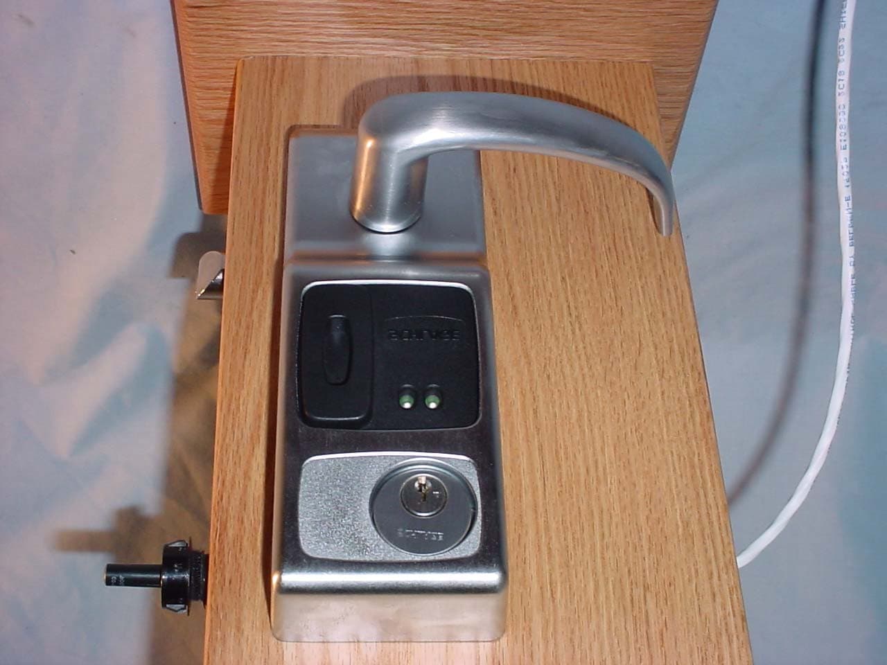
P2GVIP
Feb 09, 2004Door Lock
Equipment Class
DXX - Part 15 Low Power Communication Device Transmitter
P2GPX
Aug 25, 2003Door Lock
Equipment Class
DXX - Part 15 Low Power Communication Device Transmitter
P2G2PXI
Feb 04, 2003Door Lock
Equipment Class
DXX - Part 15 Low Power Communication Device Transmitter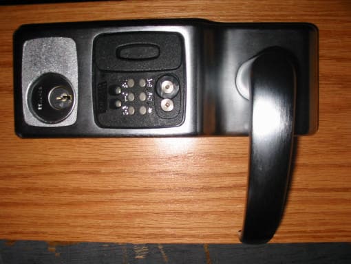
P2GPROXIF
Jan 15, 2003Door Lock
Equipment Class
DXX - Part 15 Low Power Communication Device Transmitter