P2GPROXIFDoor Lock
Schlage Electronic Security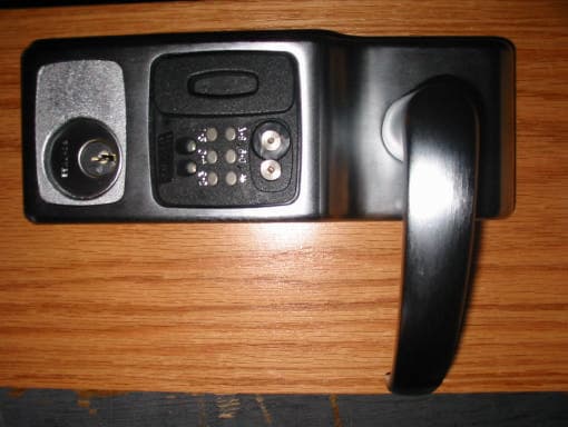
Click to zoom
Application Details
- Equipment Class
- DXX - Part 15 Low Power Communication Device Transmitter
- Date of Grant
- Jan 15, 2003
- Application Purpose
- Original Equipment
- Date of Application
- Jan 15, 2003
- Equipment Note
- Door Lock
- Frequency Range
- 0.12500000 - 0.12500000
- Company
- Schlage Electronic Security
- Country
- United States
Documents & Files
Document Text
Text extracted from the exhibit documents filed with the FCC. Open a document above to read the original.
Users Manual
Form 51005 Rev. D 12-02-2002 CM5100 COMPUTER MANAGED CYLINDRICAL LOCK INSTALLATION MANUAL CM5100-KPICM5100-IBO CM5100-MGKCM5100-MGI PRO5100 The 5100 series lock is a stand-alone, microprocessor controlled, electromechani- cal locking system. The 5100 employs a heavy-duty mechanical design with fewer moving parts than a standard cylindrical lockset, for ease of installation and high reliability. It is powered by four, standard AA batteries, providing up to 80,000 acti- vations. Operationally, the outside lever is normally locked and the inside lever is always free to allow egress. Electronic access control is achieved by entering an ”Access Credential” (magnetic stripe card, code, iButton Key, or Prox fob or card). Electronic access control capabilities are listed below by model. All models are designed to accommodate an emergency mechanical key override. Standard fea- tures of the CM models include up to 1000 user memory, real time features includ- ing time zones and holidays, and audit trail of up to 1000 events. Optional ATK (audit trail - key override) will note any use of the mechanical key on the audit trail report. Manual and computer programming is supported by all models. The PRO models are manually programmed to accept up to 100 codes. Functions : 5190: Office Function - has “Lock” and “Unlock” buttons on inside escutcheon - function not available on PRO 5196: Storeroom/Classroom Function - can be unlocked by “toggle” credential and relocked again by same. See programming guide for more information. 5198: Classroom Function with inside iButton reader - can be toggled unlocked by iButton plus pin (code). Can be relocked immediately from inside iButton reader in an emergency. Models : KPI:iButton reader and keypad IBO: iButton reader only MGK:Magnetic stripe card reader, iButton reader and keypad MGI:Magnetic stripe card reader and iButton reader PXK:HID Prox card reader, iButton reader, and keypad PXI:HID Prox card reader and iButton reader PPK:interflex ProxIF Prox card reader, iButton reader, and keypad PPI:interflex ProxIF Prox card reader and iButton reader PCK: Casi Rusco Prox card reader, iButton reader, and keypad PCI: Casi Rusco Prox card reader and iButton reader PRO: Keypad only - no computer programming, 100 code memory Options: ATK:Audit trail of mechanical key use (not available on PRO) HSS:High security screws on inside escutcheon SLB:2-3/4” backset, 1/2” latch bolt OLB:2-3/8” backset, 1/2” latch bolt ELB:2-3/4” backset, 3/4” latch bolt T3:Track 3 card reader (data on track 3 must be ABA track 2 format) - MGI/MGK only KD:Keyed Different, includes Schlage Everest cylinder LC:Less Cylinder 5100 CYLINDRICAL LOCKSET - STANDARD CM5198 SAFE SCHOOL LOCK WITH iBUTTON READER ON INSIDE CM5100-PXK CM5100-PPK CM5100-PCK CM5100-PXI CM5100-PPI CM5100-PCI Form 51005 Rev. D 12-02-20022 CM5100 COMPUTER MANAGED CYLINDRICAL LOCK INSTALLATION MANUAL 1. PREP DOOR AND FRAME: A. Determine door hand and correct backset. B. Mark the horizontal and vertical centerlines for the lockset, latch and strike. C. Place template on inside of door (opposite the side that the keypad/reader will be on). Line up the correct reference lines on the template with the edge of the door. The centerline on the door should line up with the vertical centerline of the tem- plate. D. Drill holes as described by template. BEFORE YOU BEGIN: Standard units are shipped from the factory to fit 1-3/4” doors. Verify that the door thickness. If the door is not 1-3/4” thick, verify that the door thickness option was ordered or consult factory. DOOR EDGE (LATCH) FRAME (STRIKE) DOOR FACE (LAY OUT ON INSIDE) Form 51005 Rev. D 12-02-20023 CM5100 COMPUTER MANAGED CYLINDRICAL LOCK INSTALLATION MANUAL 2. INSTALL CYLINDER (IF NOT ALREADY DONE), GASKET AND STANDOFFS: A. Install cam onto cylinder (if not already done.) Cam must be a straight, 11/16” design. See below for recommended cams. B. Insert mortise cylinder into outside escutcheon from front (keypad/reader) side with keyway down. C. Slide lock washer onto cylinder (tab on top facing out, as shown below.) D. Using nut tool (provided) tighten nut onto cylinder. E. Line up nearest notch on nut with tab on lock washer and bend tab using nut tool so nut is secure. F. Install exterior gasket (if used). G. Install standoffs. TEST KEY OPERATION NOW: Turning key clockwise until it stops (about 1/2 turn) should allow the lever to turn retractor. CYLINDER RECOMMENDED CAMS: SCHLAGE EVEREST: P/N B502-948 SCHLAGE CLASSIC: P/N B502-191 NUTTOOL RETRACTORASSEMBLY LOCKWASHER NUT STANDOFFS EXTERIORGASKET TAB NOTE: BLOCKINGRINGREQUIREDFORCYLINDER LENGTHGREATERTHAN1-1/8”. THICKNESS = CYLINDER LENGTH - 1 1/8” Form 51005 Rev. D 12-02-20024 CM5100 COMPUTER MANAGED CYLINDRICAL LOCK INSTALLATION MANUAL 3. CHANGE HAND (IF NECESSARY): NOTE:The locks are shipped handed as ordered from factory. If it is necessary to change the hand of the lock, follow the steps below: A. Remove retractor by loosening two 9/64” socket cap screws which attach it to the outside escutcheon. B. Remove outside spindle. C. Loosen 5/32” socket cap screw which secures handle to escutcheon. D. Remove, rotate and re-install handle (NOTE: some handle designs have an adapter.) E. Re-install outside spindle, making sure that the round end faces the handle, and the spindle is positioned with its edges vertical and horizontal as shown in detail below. Note that the cam (inside the escutcheon assembly) must be positioned such that the dot on it faces the 6 O’Clock position (see detail below). F. Rotate retractor and re-install it. G. Change the hand of the handle on the inside escutcheon (not show) the same way. Note that the inside escutcheon has no retractor. OUTSIDEESCUTCHEON OUTSIDESPINDLE (ROUNDSIDETOWARDLEVER) 9/64” SOCKETCAP SCREW 5/32” SOCKETCAP SCREW RETRACTOR OUTSIDEHANDLE DOT- FACES DOWN OUTSIDE SPINDLE POSITION CAM DETAIL ADAPTER LEVER NOTE: Some lever designs require an adapter. Form 51005 Rev. D 12-02-20025 CM5100 COMPUTER …
Text truncated - open the document above for the full version.
Users Manual
Form 55005 Rev. D 12-02-2002 CM5500 COMPUTER MANAGED MORTISE LOCK INSTALLATION MANUAL CM5500-KPICM5500-IBO CM5500-MGKCM5500-MGI PRO5500 The 5500 series lock is a stand-alone, microprocessor controlled, electromechanical locking system. The 5500 employs a heavy-duty mechanical design with fewer moving parts that a standard mechanical mortise lockset, for ease of installation and high reliability. It is pow- ered by four, standard AA batteries, providing up to 80,000 activations. Operationally, the outside lever is normally locked and the inside lever always retracts the bolt to allow egress. Electronic access control is achieved by entering an”Access Credential” (magnetic stripe card, code of iButton Key, or Prox fob or card). Electronic access control capabilities are listed below by model. All models are designed to accommodate an emergency mechanical key override. Standard features of the CM models include up to 1000 user memory, real time features including time zones and holidays, and audit trail of up to 1000 events. Optional ATK (audit trail - key override) will note any use of the mechanical key on the audit trail report. Manual and computer programming is supported by all models. The PRO models are manually programmed to accept up to 100 codes. Functions : 5590: Office Function (3/4” latch) - has “Lock” and “Unlock” buttons on inside escutcheon. Function not available on PRO 5596: Storeroom/Classroom Function (3/4” latch) - can be unlocked by “toggle” credential and relocked again by same. See programming guide for more information (form 57000). 5598: Classroom Function with inside iButton reader - can be toggled unlocked by iButton plus pin (code). Can be relocked immediately from inside iButton reader in an emergency. 5591: Office Function (1” Autobolt) - has “Lock” and “Unlock” buttons on inside escutcheon. Function not available on PRO 5594: Storeroom/Classroom Function (1” Autobolt) - can be unlocked by “toggle” credential and relocked again by same. See programming guide for more information (form 57000). Function not available on PRO 5593: Dormitory/Privacy Function (1” Autobolt) - Pushing “Privacy On” button on the inside escutcheon places lock in the “Privacy” mode: a “Lockout” credential or mechanical key is required to enter. Condition is cleared when the bolt is retracted from the inside or by pushing the “Privacy Off” button. Function not available on PRO. Models : KPI:iButton reader and keypad IBO: iButton reader only MGK:Magnetic stripe card reader, iButton reader and keypad MGI:Magnetic stripe card reader and iButton reader PXK:HID Prox card reader, iButton reader, and keypad PXI:HID Prox card reader and iButton reader PPK:interflex ProxIF Prox card reader, iButton reader, and keypad PPI:interflex ProxIF Prox card reader and iButton reader PCK: Casi Rusco Prox card reader, iButton reader, and keypad PCI: Casi Rusco Prox card reader and iButton reader PRO: Keypad only - Manual programming only, 100 code memory Options : ATK:Audit trail of mechanical key use (not available on PRO) HSS:High security screws on inside escutcheon T3:Track 3 card reader (data must be ABA track 2 for mat) - MGI/MGK only KD:Keyed Different, includes Schlage Everest cylinder LC:Less Cylinder 5500 MORTISE LOCK AUTOBOLT 5500 MORTISE LOCK STANDARD CM5598 SAFE SCHOOL LOCK WITH iBUTTON READER ON INSIDE CM5500-PXK CM5500-PPK CM5500-PCK CM5500-PXI CM5500-PPI CM5500-PCI Form 55005 Rev. D 12-02-20022 CM5500 COMPUTER MANAGED MORTISE LOCK INSTALLATION MANUAL 1. PREP DOOR AND FRAME (IF NOT ALREADY DONE): A. Determine door hand. B. Mark the horizontal and vertical centerlines for the lock case (on door edge), strike, lever, and inside escutcheon. Note that the backset is actually 2.813” (or 2 13/16”). This is very important for proper mounting. C. Place template on insideof door (opposite the side that the keypad/reader will be on). Line up the correct reference lines on the template with the edge of the door, depending on the hand (see paper template). The centerline on the door should line up with the vertical centerline of the template. Use the paper template to mark all holes. (Though the paper template is the preferred way to prep the door, the dimensions below may be used if a paper template is not available.) D. Drill required holes. Note that all holes are required except the 3/4” hole just below the 1” hole, this is only required if the lock has the privacy feature (model 5593). BEFORE YOU BEGIN: Standard units are shipped from the factory to fit 1-3/4” doors. Verify the door thickness. If the door is not 1-3/4” thick, verify that the door thickness option was ordered or consult factory. Form 55005 Rev. D 12-02-20023 CM5500 COMPUTER MANAGED MORTISE LOCK INSTALLATION MANUAL 2. INSTALL CYLINDER, GASKET AND STANDOFFS: A. Install cam onto cylinder. Cam can be either a cloverleaf (shown) or straight, 11/16” design (not shown). B. Insert standard, 1-1/8” mortise cylinder into outside escutcheon from front (keypad/reader) side with keyway down. C. Slide lock washer into place with tab on top facing out, as shown below. D. Using nut tool (provided) tighten nut onto cylinder. E. Line up nearest notch on nut with tab on lock washer and bend tab into notch using nut tool so nut is secure. F. Install exterior gasket (if used). G. Install upper and lower standoffs. CYLINDER RECOMMENDED CAM: SCHLAGE EVEREST: P/N B502-948 SCHLAGE CLASSIC: P/N B502-191 NUTTOOL EXTERIORGASKET LOCKWASHER NUT STANDOFFS- UPPER STANDOFFS- LOWER TAB NOTE: BLOCKINGRINGREQUIREDFORCYLINDER LENGTHGREATERTHAN1-1/8”. THICKNESS = CYLINDER LENGTH -1 1/8” Form 55005 Rev. D 12-02-20024 CM5500 COMPUTER MANAGED MORTISE LOCK INSTALLATION MANUAL 3. CHANGE HAND (IF NECESSARY): NOTE:The locks are shipped as ordered from factory. If it is necessary to change the hand of the lock, follow the steps below: TO CHANGE HAND OF LOCK CASE: A. With bolt fully extended, insert change pin (included in the hardware pack) into hole. (It will snap over a groove o…
Text truncated - open the document above for the full version.
Cover Letter(s)
Federal Communications Commission 7435 Oakland Mills Road Columbia, MD 21046 Gentlemen: This letter is to comply with 47 CFR 0.457(d)(2) pertaining to confidential material. Ingersoll-Rand/Locknetics requests that the following documents regarding this submission for FCC ID P2GPROXIF be kept confidential: 1. Schematic 2. Block Diagram 3. Circuit Description The material above contains technical data, which would customarily be guarded from competitors. We are requesting confidentiality with regards to the preceding documents. Sincerely, Roland D. Cyr Electronic Technician IR Security & Safety Solutions 20 Dolphin Road P.O. Box 9338 Forestville, CT 06011-9338 [email protected] 860-314-5357 (Direct) 860-582-8300 (Main) 860-582-8304 (Fax) Ingersoll-Rand Company Security & Safety Solutions 20 Dolphin Road PO Box 9338 Forestville, CT 06011-9338 (860) 582-8300 (860) 582-8304 Fax
Cover Letter(s)
Barry Quinlan From: "Michael Buchholz" <[email protected]> To: "Curtis-Straus Certification Dept." <[email protected]> Sent: Wednesday, January 15, 2003 4:18 PM Sub ject: Re: IR Security and Safety Solutions FCC ID: P2GPROXIF Page 1 of 1 1/16/2003 1) New form 731 has been sent. 2) A fresh battery was used for testing. 3) The magnetic loop antenna was rotated to fully maximize each emission. Regards, Mike ----- Original Message ----- From: Curtis -Straus Certification Dept. To: Mike Buchholz Sent: Wednesday, January 15, 2003 6:51 PM Subject: IR Security and Safety Solutions FCC ID: P2GPROXIF Hi Mike, Our reviewers have identified the following issues: 1. Grantee code P2G is assigned to Locknetics not IR Security and Safety Solutions as shown on the form 731. 2. Please confirm a new battery was used during the testing. 3. Please confirm that the loop antenna was rotated to maximize emissions. Best regards Barry C. Quinlan Certification Manager Curtis-Straus TCB
External Photos
External Photos Model: CM5100-PPK FCC ID: P2GPROXIF Model: CM5100-PPK FCC ID: P2GPROXIF
ID Label/Location Info
Label Placement
Internal Photos
Internal Photos Model: CM5100-PPK FCC ID: P2GPROXIF Model: CM5100-PPK FCC ID: P2GPROXIF Model: CM5100-PPK FCC ID: P2GPROXIF Model: CM5100-PPK FCC ID: P2GPROXIF Model: CM5100-PPK FCC ID: P2GPROXIF Model: CM5100-PPK FCC ID: P2GPROXIF Model: CM5100-PPK FCC ID: P2GPROXIF Model: CM5100-PPK FCC ID: P2GPROXIF Model: CM5100-PPK FCC ID: P2GPROXIF Model: CM5100-PPK FCC ID: P2GPROXIF Model: CM5100-PPK FCC ID: P2GPROXIF Model: CM5100-PPK FCC ID: P2GPROXIF Model: CM5100-PPK FCC ID: P2GPROXIF
Operational Description
Please note an additional part number that we also want included with this application, that of the Casi-Rusco prox cards. These use the exact same hardware as the ProxIF. The part numbers are: PROXIF: Cylindrical Series Proxif, iButton and keypad CM5100-PPK Cylindrical Series Proxif, iButton CM5100-PPI Mortise Series Proxif, iButton and keypad CM5500-PPK Mortise Series Proxif, iButton CM5500-PPI CASI-RUSCO: Cylindrical Series Casi-Rusco, iButton and keypad CM5100-PCK Cylindrical Series Casi-Rusco, iButton CM5100-PCI Mortise Series Casi-Rusco, iButton and keypad CM5500-PCK Mortise Series Casi-Rusco, iButton CM5500-PCI
Test Report
Curtis-Straus LLC is accredited by the American Association for Laboratory Accreditation for the specific scope of accreditation under Certificate Number 1627-01. This report may contain data which is not covered by the A2LA accreditation. _____________________________________________________________ Curtis-Straus LLC •• 527 Great Road •• Littleton, MA •• TEL (978) 486-8880 •• FAX (978) 486-8828 Test Report Report No EC0895-1 Client Locknetics 20 Dolphin Road P.O. Box 9338 Forestville, CT 06011-9338 Phone 860-582-8300 Fax 860-582-8304 FRN 0005178298 Models CM5100-PPK, CM5100-PPI, CM5500-PPK, CM5500-PPI CM5100-PCK, CM5100-PCI, CM5500-PCK, CM5500-PCI FCC ID P2GPROXIF Equipment Type Low Power Communication Device Transmitter Equipment Code DXX Results As detailed within this report Prepared by _____________________ Evan Gould – Test Engineer Authorized by __________________________ Michael Buchholz – EMC Manager Issue Date __12/12/02___ Conditions of issue This Test Report is issued subject to the conditions stated in ‘terms and conditions’ section of this report. REPORT: EC0895-1 FCC ID: P2GPROXIF Page 2 of 8 _____________________________________________________________ Curtis-Straus LLC •• 527 Great Road •• Littleton, MA •• TEL (978) 486-8880 •• FAX (978) 486-8828 Table Of Contents Summary.........................................................................................................................3 Test Methodology........................................................................................................3 Statement of Conformity..........................................................................................4 Fundamental Frequency Measurement............................................................5 Test Equipment Used................................................................................................6 Terms And Conditions..............................................................................................7 REPORT: EC0895-1 FCC ID: P2GPROXIF Page 3 of 8 _____________________________________________________________ Curtis-Straus LLC •• 527 Great Road •• Littleton, MA •• TEL (978) 486-8880 •• FAX (978) 486-8828 Summary This report is an application for Certification of a Transmitter operating pursuant to Part 15.209 of the FCC Rules, Code of Federal Regulations 47. The models covered by this report are: CM5100-PPK CM5100-PPI CM5100-PCK CM5100-PCI CM5500-PPK CM5500-PPI CM5500-PCK CM5500-PCI The model tested was the CM5100-PPK. This is considered to be the worst case representative of the models shown above. This report is designed to demonstrate the compliance of this device with the requirements outlined in 47 CFR Part 15 using the methods outlined in 47 CFR Part 2. Test Methodology Radiated emissions testing is performed according to the procedures specified in ANSI C63.4 (2000). Frequency range investigated: 9kHz – 1GHz Measurement distance: 1 Meter Maximization: EUT rotated around vertical axis REPORT: EC0895-1 FCC ID: P2GPROXIF Page 4 of 8 _____________________________________________________________ Curtis-Straus LLC •• 527 Great Road •• Littleton, MA •• TEL (978) 486-8880 •• FAX (978) 486-8828 Statement of Conformity The Locknetics CM5100-PPK has been found to conform with the following parts of the 47 CFR as detailed below: Part 2 Part 15 Comments 15.15(b) The product contains no user accessible controls that increase transmission power above allowable levels. 2.925 15.19 The label is shown in the label exhibit. 15.21 Information to the user is shown in the instruction manual exhibit. 15.27 No special accessories are required for compliance. 15.203 The antenna is not accessible to the user and therefore cannot be easily removed. (The antenna and its connector are underneath the keypad assembly which is in turn professionally installed in the door lock enclosure.) 15.205 15.209 The fundamental is not in a Restricted band and the spurious and harmonic emissions in the Restricted bands comply with the general emission limits of 15.209. 15.207 The unit is battery powered without the capability of being recharged or operated from the AC mains. REPORT: EC0895-1 FCC ID: P2GPROXIF Page 5 of 8 _____________________________________________________________ Curtis-Straus LLC •• 527 Great Road •• Littleton, MA •• TEL (978) 486-8880 •• FAX (978) 486-8828 Fundamental Frequency Measurement LIMITS Frequency (MHz) Limit (μV/m) Measurement Distance (meters) 0.009-0.49 2400/F(kHz) 300 0.49-1.705 24000/F(kHz) 30 1.705-30 30 30 30-88 100 3 88-216 150 3 216-960 200 3 Above 960 500 3 [47 CFR 15.209] MEASUREMENTS Fundamental and Harmonics (9kHz-1GHz) Curtis-Straus LLC Date:15-Nov-02Engineer:Evan GouldWork Order:C0895 Company:LockneticsEUT:CM5100 - PPKFundamental Frequency:125kHz Test Site:"F"Cable:65 ft RG8A/UPre-amp:Red Antennas:Small Loop (9kHz-30MHz)Filter/Attenuator:N/AAnalyzer:Yellow Blue (30MHz-1GHz) Measurement Distance:1 meterResolution BW:9kHz Detector Type:PeakVideo BW:1MHz Notes:No spurious emissions were detected. AntennaPreampAntennaCableFilter/AttenuatorDistanceAdjusted 47 CFR 15.209 PolarizationFrequencyReadingFactorFactorFactorFactorFactorReadingLimitMarginResult (0° / 90°)(MHz)(dBμV)(dB)(dB/m)(dB)(dB)(dB)(dBμV/m)(dBμV/m)(dB)(Pass/Fail) 0° 0.12559.421.762.70.00.099.01.425.6-24.2Pass 0° 0.2548.122.057.70.00.099.0-15.219.6-34.8Pass 0° 0.37533.922.055.40.00.099.0-31.716.1-47.8Pass 0° 0.533.922.153.10.00.059.05.933.6-27.7Pass 0° 0.62528.622.152.20.00.059.0-0.331.6-31.9Pass 0° (noise floor) 0.7516.022.151.50.00.059.0-13.630.0-43.6Pass 0° 0.87521.722.051.10.00.059.0-8.228.7-36.9Pass 0° (noise floor) 1.028.222.050.80.00.059.0-2.027.6-29.6Pass 0° (noise floor) 1.1325.222.055.50.00.059.0-0.326.5-26.8Pass 0° (noise floor) 1.2528.622.054.80.00.059.02.425.6-23.2Pass FUNDAMENTAL ANALYZER PLOT REPORT: EC0895-1 FCC ID: P2GPROXIF Page 6 of 8 _____________________________________________________________ Curtis-Straus LLC •• 527 Great Road •• Littleton, …
Text truncated - open the document above for the full version.
Contact Information
Applicant
Adam O'Day(Electronic Engineer)
Test Firm
Curtis-Straus LLCJonathan Stewart
Technical Specifications
| # | Rule Parts | Frequency Range | Power Output |
|---|---|---|---|
| 1 | 15C | 0.125 MHz - 0.125 MHz | - |
Other Applications from Schlage Electronic Security

P2G-RDR-ICL
Feb 06, 2005Door Lock with Proximity Reader Transmitter
Equipment Class
DXX - Part 15 Low Power Communication Device Transmitter
P2GPXH
Oct 25, 2004Door Lock
Equipment Class
DXX - Part 15 Low Power Communication Device Transmitter
P2GVIP
Feb 09, 2004Door Lock
Equipment Class
DXX - Part 15 Low Power Communication Device Transmitter
P2GPX
Aug 25, 2003Door Lock
Equipment Class
DXX - Part 15 Low Power Communication Device Transmitter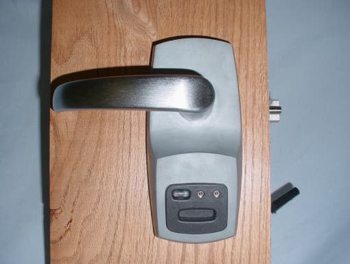
P2G2PXI
Feb 04, 2003Door Lock
Equipment Class
DXX - Part 15 Low Power Communication Device Transmitter