P2GIRCDoor Lock Low Power Proximity Transmitter
Schlage Electronic Security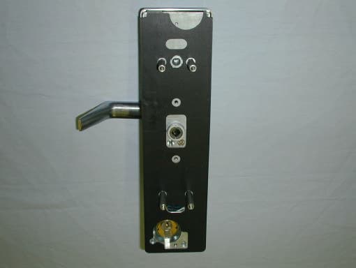
Click to zoom
Application Details
- Equipment Class
- DXX - Part 15 Low Power Communication Device Transmitter
- Date of Grant
- Jan 28, 2002
- Application Purpose
- Original Equipment
- Date of Application
- Jan 28, 2002
- Equipment Note
- Door Lock Low Power Proximity Transmitter
- Frequency Range
- 0.12500000 - 0.12500000
- Company
- Schlage Electronic Security
- Country
- United States
Documents & Files
Document Text
Text extracted from the exhibit documents filed with the FCC. Open a document above to read the original.
Users Manual
Form 55005 Rev. B 09-25-2001 CM5500 COMPUTER MANAGED MORTISE LOCK INSTALLATION MANUAL CM5500-KPICM5500-IBO CM5500-MGKCM5500-MGI CM5500-PXKCM5500-PXI PRO5500 The 5500 series lock is a stand-alone, microprocessor controlled, electromechani- cal locking system. The 5500 employs a heavy-duty mechanical design with fewer moving parts that a standard mechanical mortise lockset, for ease of installation and high reliability. It is powered by four, standard AA batteries, providing up to 80,000 activations. Operationally, the outside lever is normally locked and the inside lever always retracts the bolt to allow egress. Electronic access control is achieved by entering an”Access Credential” (magnetic stripe card, code of iButton Key, or HID Prox fob or card). Electronic access control capabilities are listed below by model. All mod- els are designed to accommodate an emergency mechanical key override. Standard features of the CM models include up to 1000 user memory, real time features including time zones and holidays, and audit trail of up to 1000 events. Optional ATK (audit trail - key override) will note any use of the mechanical key on the audit trail report. Manual and computer programming is supported by all mod- els. The PRO models are manually programmed to accept up to 100 codes. Functions: 5590: Office Function (3/4” latch) - has “Lock” and “Unlock” buttons on inside escutcheon. Function not available on PRO 5596: Storeroom/Classroom Function (3/4” latch) - can be unlocked by “toggle” credential and relocked again by same. See programming guide for more informa- tion (form 57000). 5598: Classroom Function with inside iButton reader - can be toggled unlocked by iButton plus pin (code). Can be relocked immediately from inside iButton reader in an emergency. 5591: Office Function (1” Autobolt) - has “Lock” and “Unlock” buttons on inside escutcheon. Function not available on PRO 5594: Storeroom/Classroom Function (1” Autobolt) - can be unlocked by “toggle” credential and relocked again by same. See programming guide for more informa- tion (form 57000). Function not available on PRO 5593: Dormitory/Privacy Function (1” Autobolt) - Pushing either button on the inside escutcheon places lock in the “Privacy” mode: a “Lockout” credential or mechanical key is required to enter. Condition is cleared when the bolt is retracted from the inside. Function not available on PRO Models : KPI:iButton reader and keypad IBO: iButton reader only MGK:Magnetic stripe card reader, iButton reader and keypad MGI:Magnetic stripe card reader and iButton reader PXK:Prox card reader, iButton reader, and keypad PXI:Prox card reader and iButton reader PRO:Keypad only - Manual programming only, 100 code memory Options: ATK:Audit trail of mechanical key use (not available on PRO) HSS:High security screws on inside escutcheon T3:Track 3 card reader (data must be ABA track 2 for- mat) - MGI/MGK only KD:Keyed Different, includes Schlage Everest cylinder LC:Less Cylinder 5500 MORTISE LOCK AUTOBOLT 5500 MORTISE LOCK STANDARD CM5598 SAFE SCHOOL LOCK WITH iBUTTON READER ON INSIDE Form 55005 Rev. B 09-25-20012 CM5500 COMPUTER MANAGED MORTISE LOCK INSTALLATION MANUAL 1. PREP DOOR AND FRAME (IF NOT ALREADY DONE): A. Determine door hand. B. Mark the horizontal and vertical centerlines for the lock case (on door edge), strike, lever, and inside escutcheon. Note that the backset is actually 2.813” (or 2 13/16”). This is very important for proper mounting. C. Place template on insideof door (opposite the side that the keypad/reader will be on). Line up the correct reference lines on the template with the edge of the door, depending on the hand (see paper template). The centerline on the door should line up with the vertical centerline of the template. Use the paper template to mark all holes. (Though the paper template is the preferred way to prep the door, the dimensions below may be used if a paper template is not available.) D. Drill required holes. Note that all holes are required except the 3/4” hole just below the 1” hole, this is only required if the lock has the privacy feature (model 5594). BEFORE YOU BEGIN: Standard units are shipped from the factory to fit 1-3/4” doors. Verify the door thickness. If the door is not 1-3/4” thick, verify that the door thickness option was ordered or consult factory. Form 55005 Rev. B 09-25-20013 CM5500 COMPUTER MANAGED MORTISE LOCK INSTALLATION MANUAL 2. INSTALL CYLINDER, GASKET AND STANDOFFS: A. Install cam onto cylinder. Cam can be either a cloverleaf (shown) or straight, 11/16” design (not shown). B. Insert standard, 1-1/4” mortise cylinder into outside escutcheon from front (keypad/reader) side with keyway down. C. Slide lock washer into place with tab on top facing out, as shown below. D. Using nut tool (provided) tighten nut onto cylinder. E. Line up nearest notch on nut with tab on lock washer and bend tab into notch using nut tool so nut is secure. F. Install exterior gasket (if used). G. Install upper and lower standoffs. CYLINDER RECOMMENDED CAM: SCHLAGE P/N B502-948 NUTTOOL EXTERIORGASKET LOCKWASHER NUT STANDOFFS- UPPER STANDOFFS- LOWER TAB Form 55005 Rev. B 09-25-20014 CM5500 COMPUTER MANAGED MORTISE LOCK INSTALLATION MANUAL 3. CHANGE HAND (IF NECESSARY): NOTE:The locks are shipped as ordered from factory. If it is necessary to change the hand of the lock, follow the steps below: TO CHANGE HAND OF LOCK CASE: A. With bolt fully extended, insert change pin (included in the hardware pack) into hole. (It will snap over a groove on the main shaft, holding it in place.) B. Remove set screw in bolt so bolt can be removed. C. Rotate bolt and reinstall on to shaft. Do not remove spring. D. Apply thread locking compound to set screw. Loctite 242 recommended. E. Install and tighten set screw (from other side, as shown). F. Remove change pin. 5/32” SOCKETCAPSCREW LOCTITE242 RECOMMENDED OUTSIDEESCUTCHEON ADAPTER LEVER OUTSIDEHANDLE CHANGEPIN LOCKCASE BOLT (AUTOBOLTSHOWN) TO CHANGE HAND OF LEV…
Text truncated - open the document above for the full version.
Cover Letter(s)
Curtis-Straus LLC 527 Great Road Littleton, Massachusetts 01460 Tel: 978.486.8880 Fax: 978.486.8828 Web: www.curtis-straus.com e-mail: [email protected] Worldwide Regulatory Approvals Experts ® Federal Communications Commission 7435 Oakland Mills Road Columbia, MD 21046 Gentlemen: This letter is to comply with 47 CFR 0.457(d)(2)(I) pertaining to confidential material. Locknetics Security Engineering requests that the following documents regarding this submission for FCC ID P2GIRC be kept confidential: 1. Schematic 2. Bill of Materials 3. Block Diagram 4. Circuit Description The material above contains technical data, which would customarily be guarded from competitors. We at Curtis-Straus LLC are acting as an Agent on behalf of Locknetics Security Engineering in requesting confidentiality with regards to the preceding documents. Sincerely, Michael Buchholz Senior EMC Manager Curtis-Straus LLC 527 Great Road Littleton, MA 01460
External Photos
External Photographs Locknetics CM5100, CM5500, CM5700, and CM993 Series FCC ID: P2GIRC Locknetics CM5100, CM5500, CM5700, and CM993 Series FCC ID: P2GIRC
ID Label/Location Info
Label Placement for Schlage locks
ID Label/Location Info
Label Placement for Von Duprin locks
Test Report
MEASUREMENT/TECHNICAL REPORT Company: Locknetics Security Engineering Models: CM5100, CM5500, CM5700 and CM993 Series FCC ID: P2GTBD November 21, 2001 Description: This is a report to support a request for an original grant of equipment authorization. Equipment Type: Low Power Communications Device Transmitter (DXX) Report prepared for: Locknetics Security Engineering 575 Birch Street Forestville, CT 06010 Phone: (860) 584-9158 Fax: (860) 585-2136 Report prepared by: Evan D. Gould Curtis-Straus LLC 527 Great Road Littleton, MA 01460 USA Phone: 978-486-8880 FAX: 978-486-8828 FCC Application for Locknetics Security Engineering •• FCC ID:P2GTBD •• Report No. EB1012-1 21-Nov-01 ______________________________________________________________________ _____________________________ ________________________________ Curtis-Straus LLC •• 527 Great Road •• Littleton, MA •• TEL (978) 486-8880 •• FAX (978) 486-8828 page 2 of 13 Introduction This report is an application for Certification of a Transmitter operating pursuant to Part 15.209 of the FCC Rules, Code of Federal Regulations 47. The model numbers covered by this report are the CM5100, CM5500, CM5700, and CM993 Series. This report is designed to demonstrate the compliance of this device with the requirements outlined in Part 15 of CFR 47 using the methods outlined in Part 2 of CFR 47. FCC Application for Locknetics Security Engineering •• FCC ID:P2GTBD •• Report No. EB1012-1 21-Nov-01 ______________________________________________________________________ _____________________________ ________________________________ Curtis-Straus LLC •• 527 Great Road •• Littleton, MA •• TEL (978) 486-8880 •• FAX (978) 486-8828 page 3 of 13 Statement of Conformity The Locknetics CM5100, CM5500, CM5700, and CM993 Series door locks have been found to conform with the following parts of the 47 CFR as detailed below: Part 2 Part 15 Comments 15.15(b) The product contains no user accessible controls that increase transmission power above allowable levels. 2.925 15.19 The label is shown in the label exhibit. 15.21 Information to the user is shown in the instruction manual exhibit. 15.27 No special accessories are required for compliance. 15.203 The antenna is not accessible to the user and therefore cannot be easily removed. (The antenna and its connector are underneath the keypad assembly which is in turn professionally installed in the door lock enclosure.) 15.205 15.209 The fundamental is not in a Restricted band and the spurious and harmonic emissions in the Restricted bands comply with the general emission limits of 15.209. 15.207 The unit is battery powered without the capability of being recharged or operated from the AC mains. FCC Application for Locknetics Security Engineering •• FCC ID:P2GTBD •• Report No. EB1012-1 21-Nov-01 ______________________________________________________________________ _____________________________ ________________________________ Curtis-Straus LLC •• 527 Great Road •• Littleton, MA •• TEL (978) 486-8880 •• FAX (978) 486-8828 page 4 of 13 Test Methodology Radiated emission testing was performed according to the procedures in ANSI C63.4 (1992). The testing was performed at an antenna to EUT distance of 3 or 1 meter(s). The actual test distance used is noted in the test data sheets. The device’s performance was investigated to 1GHz. The EUT was powered by four AA batteries. Fresh batteries were used for all testing. Since the device is normally installed in one orientation, the emissions were maximized around the vertical axis and the maximum reading was recorded. The integrated antenna cannot be maximized separately. All other performance tests were made in accordance with the procedures outlined in Part 15 of CFR 47. The applicable sections provided under Part 15 are provided in the measurement section of this report. FCC Application for Locknetics Security Engineering •• FCC ID:P2GTBD •• Report No. EB1012-1 21-Nov-01 ______________________________________________________________________ _____________________________ ________________________________ Curtis-Straus LLC •• 527 Great Road •• Littleton, MA •• TEL (978) 486-8880 •• FAX (978) 486-8828 page 5 of 13 Test Facility Curtis-Straus LLC All testing for the range 9kHz–1000MHz was performed at Curtis-Straus (A2LA Certificate Number 1627-01). The open area test site used to collect the radiated data is located at 527 Great Road, Littleton, MA 01460. Site “T” was used. FCC Application for Locknetics Security Engineering •• FCC ID:P2GTBD •• Report No. EB1012-1 21-Nov-01 ______________________________________________________________________ _____________________________ ________________________________ Curtis-Straus LLC •• 527 Great Road •• Littleton, MA •• TEL (978) 486-8880 •• FAX (978) 486-8828 page 6 of 13 Test Equipment Used SPECTRUM ANALYZERS x Analyzer Model No. Company Serial No. Calibration Due ORANGE 9kHz-26.5GHz E4407B HP US39440975 18-MAY-2002 OPEN AREA TEST SITES (OATS) x Site FCC Code IC Code VCCI Code Calibration Due “T” Texas 93448 IC 2762-T R-905/ C-480 09-SEP-2002 ANTENNAS x Antenna Model No. Company Serial No. Calibration Due GREEN-WHITE Bilog: 30MHz-2GHz CBL6112B Chase 2574 28-JUN-2002 LARGE LOOP Passive Loop: 20Hz-5MHz 6511 EMCO 9704-1154 06-NOV-2001 PREAMPLIFIERS x Preamplifier Model No. Company Serial No. Calibration Due GREEN 0.01-2000MHz ZFL-1000-LN MiniCircuits/ C-S n/a 24-MAR-2002 Unless otherwise noted the calibration interval is one year. All equipment is calibrated using standards traceable to NIST or other nationally recognized calibration standard. FCC Application for Locknetics Security Engineering •• FCC ID:P2GTBD •• Report No. EB1012-1 21-Nov-01 ______________________________________________________________________ _____________________________ ________________________________ Curtis-Straus LLC •• 527 Great Road •• Littleton, MA •• TEL (978) 486-8880 •• FAX (978) 486-8828 page 7 of 13 Measurement Results Operating Frequency This device operates at 125kH…
Text truncated - open the document above for the full version.
Test Setup Photos
Page 1 of 1 file://E:\Locknetic\B1011\Setup Photo.jpg10/10/01
Contact Information
Applicant
Adam O'Day(Electronic Engineer)
Test Firm
Curtis-Straus LLCJonathan Stewart
Technical Specifications
| # | Rule Parts | Frequency Range | Power Output |
|---|---|---|---|
| 1 | 15C | 0.125 MHz - 0.125 MHz | - |
Other Applications from Schlage Electronic Security

P2G-RDR-ICL
Feb 06, 2005Door Lock with Proximity Reader Transmitter
Equipment Class
DXX - Part 15 Low Power Communication Device Transmitter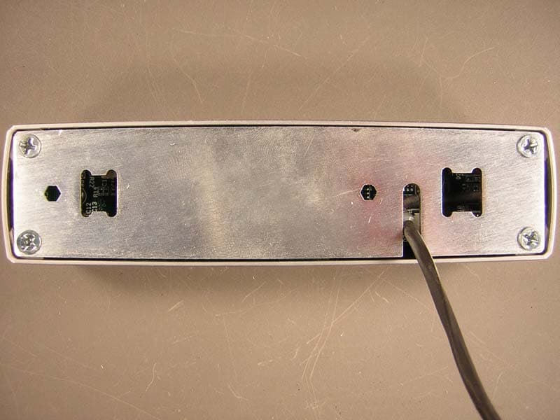
P2GPXH
Oct 25, 2004Door Lock
Equipment Class
DXX - Part 15 Low Power Communication Device Transmitter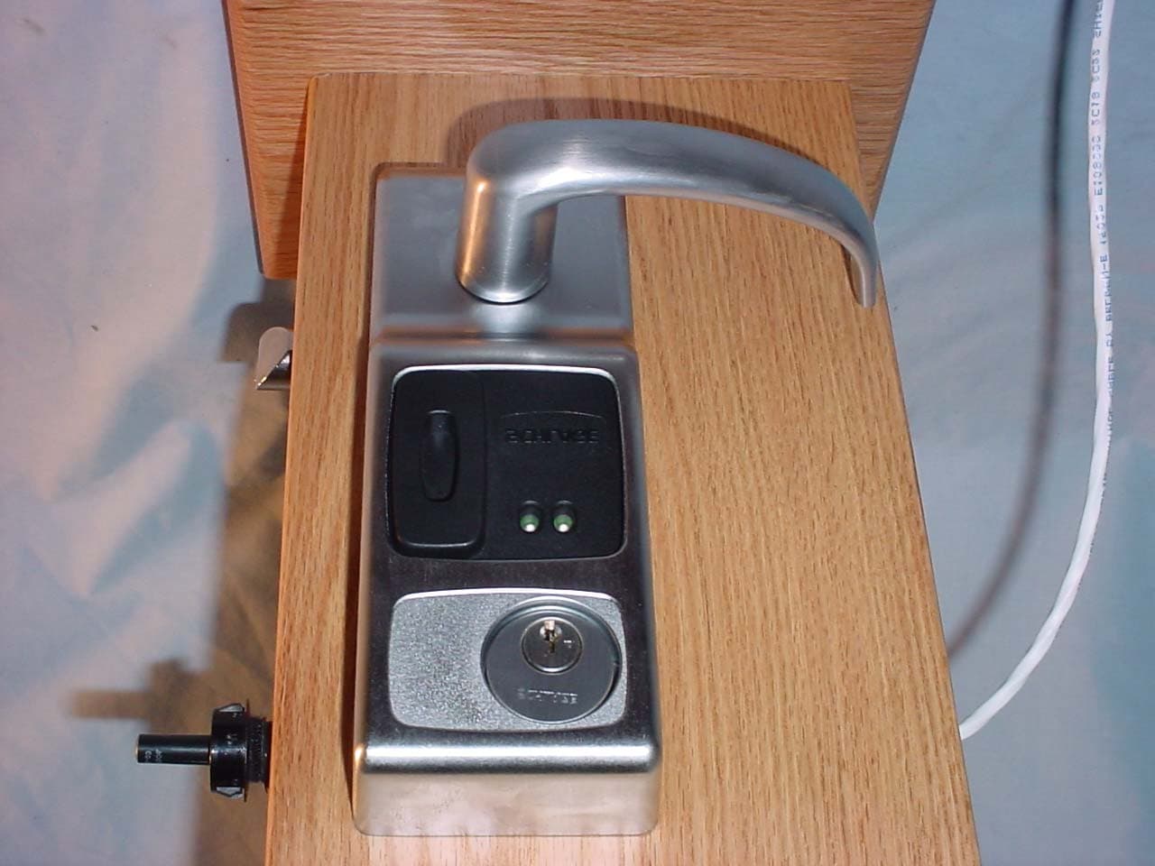
P2GVIP
Feb 09, 2004Door Lock
Equipment Class
DXX - Part 15 Low Power Communication Device Transmitter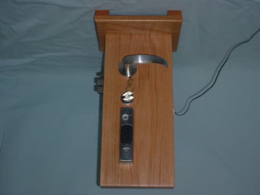
P2GPX
Aug 25, 2003Door Lock
Equipment Class
DXX - Part 15 Low Power Communication Device Transmitter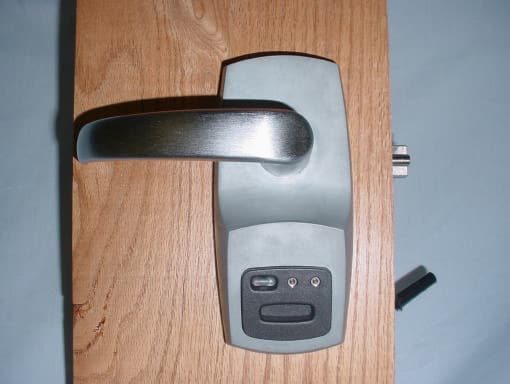
P2G2PXI
Feb 04, 2003Door Lock
Equipment Class
DXX - Part 15 Low Power Communication Device Transmitter