P4YSMT-500PMiBUS OBE (BUS Management System)
Samsung SDS Co., Ltd.
Click to zoom
Application Details
- Equipment Class
- JBC - Part 15 Class B Computing Device/Personal Computer
- Date of Grant
- Nov 19, 2013
- Application Purpose
- Original Equipment
- Date of Application
- Nov 19, 2013
- Equipment Note
- MiBUS OBE (BUS Management System)
- Company
- Samsung SDS Co., Ltd.
- Country
- South Korea
Documents & Files
Document Text
Text extracted from the exhibit documents filed with the FCC. Open a document above to read the original.
Users Manual
MiBUS OBE(SMT-500P) USER MANUAL User should uses in a distance over 20 cm 2 Copyright ⓒ 2013 Samsung SDS Co., LTD. All rights reserved | Confidential -1- 1. MiBUS OBE (BUS Management System C omposition Copyright ⓒ 2013 Samsung SDS Co., LTD. All rights reserved | Confidential -2- 2. MiBUS OBE System Block Diagram Copyright ⓒ 2013 Samsung SDS Co., LTD. All rights reserved | Confidential -3- 3. MiBUS OBE A. OBE OBE as the core device of the OBE system with 7-inch LCD with all of the inf ormation collected and processed is a device that performs. OBE coordinates of the GPS Module is based on the current location and status information of the bus created, and also through various car devices and interfaces, the st ate of the car (fuel state, RPM, etc.) and information (Turnstile, speed, cumul ative distance, etc.) collect. In addition, the control center for voice communi cation and Microphone, in the car to send to the emergency control center, p erforms for the Panic Button and interface. Information for passengers in the passenger terminal (PID) and external infor mation terminal (EID) provides information on the text, the driver of the vehi cle through a LCD monitor current service status (planned contrast variation, the current stops, etc.) and provides various alarms and messages should. B. OBE Shape Copyright ⓒ 2013 Samsung SDS Co., LTD. All rights reserved | Confidential -4- C. Specification Items Contents CPU SAMSUNG S3C6410 ARM11/MAX 667MHz Memory NAND Flash : 2GByte SDRAM : 128MByte OS Embedded Linux 2.6 Audio AC 97 Audio CODEC, External 30W Audio AMP(Stereo), Internal Speaker * 2 External Handy MIC Display 7” LCD Touch Screen (4-wire) with outdoor brightness(400nits) GPS Accuracy : 5 meters, Availability : 98%, 51 channel Key 8 Keys: Left * 4, Right * 4 Network J1939 * 1 UART * 7CH USB * 2CH(MODEM) 10/100 Ethernet(IEEE802.3) * 1 Wi-Fi(IEEE802.11b,g) Environment condition Temperature Operating Temperature: -5 ~ 85°C Humidity Operating Humidity: 5% to 95% Power Supply voltage range : DC 12 ~ 30V/Max 50W, External Battery 12V/4Ah Size 232(W) * 145(H) * 56.5(D) mm Copyright ⓒ 2013 Samsung SDS Co., LTD. All rights reserved | Confidential -5- 4. GPS Module 1. shape . Specification Items Contents CPU GPS DSP with integrated real time clock(RTC) ARM7EJ-S CPU Memory 4Mbit FLASH memory Specifications Built-in regulators (LDO) GPS receiver With Patch Antenna Patch Antenna Size : 25(W) * 25(H) * 4(D)mm Size 48(W) * 57(H) * 15(D) mm Copyright ⓒ 2013 Samsung SDS Co., LTD. All rights reserved | Confidential -6- 5.Breakout Box 1. Shape 1.1 Specification Items Contents CPU ST STM32F103 ARM Cortex-M3 72MHz Memory Internal 256kByte FLASH Internal 64Kbyte RAM Specifications Operating Temperature: -5 ~ 85°C Operating Humidity: 5% to 95% Supply voltage range : DC 12-30V/MAX 50W, External Battery 12V Size 155(W) * 80(H) * 40(D) mm Copyright ⓒ 2013 Samsung SDS Co., LTD. All rights reserved | Confidential -7- 6. Warning FCC RF INTERFERENCE STATEMENT NOTE : This equipment has been tested and found to comply with the limits for a Class B digital device, pursuant to Part 15 of the FCC Rules. These limits are designed to provide reasonable protection against harmful interference in a residential installation. This equipment generates, uses and can radiate radio frequency energy and, if not installed and used in accordance with the instructions, may cause harmful interference to radio communications. However, there is no guarantee that interference will not occur in a particular installation. If this equipment does cause harmful interference to radio or television reception which can be determined by turning the equipment off and on, the user is encouraged to try to correct the interference by one or more of the following measures. - Reorient or relocate the receiving antenna. - Increase the separation between the equipment and receiver. - Connect the equipment into an outlet on a circuit different from that to which the receiver is connected. - Consult the dealer or an experienced radio, TV technical for help. - Only shielded interface cable should be used. Finally, any changes or modifications to the equipment by the user not expressly approved by the grantee or manufacturer could void the users authority to operate such equipment Copyright ⓒ 2013 Samsung SDS Co., LTD. All rights reserved | Confidential -8- The user’s manual or instruction manual for an intentional or unintentional radiator shall caution the user that changes or modifications not expressly approved by the party responsible for compliance could void the user's authority to operate the equipment. In cases where the manual is provided only in a form other than paper, such as on a computer disk or over the Internet, the information required by this section may be included in the manual in that alternative form, provided the user can reasonably be expected to have the capability to access information in that form. For a Class B digital device or peripheral, the instructions furnished the user shall include the following or similar statement, placed in a prominent location in the text of the manual: NOTE: This equipment has been tested and found to comply with the limits for a Class B digital device, pursuant to Part 15 of the FCC Rules. These limits are designed to provide reasonable protection against harmful interference in a residential installation. This equipment generates, uses and can radiate radio frequency energy and, if not installed and used in accordance with the instructions, may cause harmful interference to radio communications. However, there is no guarantee that interference will not occur in a particular installation. If this equipment does cause harmful interference to radio or television reception, which can be determined by turning the equipment off and on, the user is encouraged to try to correct the interference by one or more of the following measures: -- Reo…
Text truncated - open the document above for the full version.
Cover Letter(s)
Samsung SDS Co., Ltd. 707-19, Youksam2-dong, Kangnam-gu, Seoul, 135-918, Korea Tel : +82-2-6484-0557 Fax. +82-2-6484-0688 Federal Communications Commission 7435 Oakland Mills Road Columbia, MD 21046 Gentlemen: This letter is to comply with Sections 0.457 and 0.459 pertaining to confidential material. Samsung SDS Co., Ltd. would like the following documents regarding this submission for FCC ID : P4YSMT-500P to be kept confidential. 1. Document {Circuit Diagram}. 2. Document {Operating Description}. 3. Document {Block Diagram} The above material contains trade secrets or technical data, which would customarily be guarded from competitors. We do not want these documents to be accessible to the general public. Sincerely, Myoung kue, Lee / SIE Group Manager
External Photos
X axis-22 cm Y axis-14 cm Z axis-5 cm SMT-500P_Front View SMT-500P_Rear View SMT-500P_Leftside View SMT-500P_Rightside View SMT-500P_Top View SMT-500P_Bottom View SMT-500P_Breakout Box_Front View SMT-500P_Breakout Box_Rear View SMT-500P_Breakout Box_Leftside View SMT-500P_Breakout Box_Rightside View SMT-500P_Breakout Box_Top View SMT-500P_Breakout Box_Bottom View SMT-500P_Battery Pack_Front View SMT-500P_Battery Pack_Rear View SMT-500P_Battery Pack_Leftside View SMT-500P_Battery Pack_Rightide View SMT-500P_Battery Pack_Top View SMT-500P_Battery Pack_Bottom View
ID Label/Location Info
ID Label Location Information
Internal Photos
SMT-500P_inner View SMT-500P_Main Board Front SMT-500P_Main Board Front-1 SMT-500P_Main Board Front-2 SMT-500P_Main Board Front-3 SMT-500P_Main Board Front-4 SMT-500P_Main Board Rear SMT-500P_Main Board Rear-1 SMT-500P_Main Board Rear-2 SMT-500P_Main Board Rear-3 SMT-500P_Main Board Rear-4 SMT-500P_RF Module SMT-500P_Core Board Front SMT-500P_Core Board Rear SMT-500P_RFID Board Front SMT-500P_RFID Board Rear SMT-500P_USB Board Front SMT-500P_USB Board Rear SMT-500P_Breakout Box_Main Board Front SMT-500P_Breakout Box_Main Board Rear SMT-500P_Battery Pack_Main Board Front SMT-500P_Battery Pack_Main Board Rear
Test Report
1 of 35 Report No.: E13WD-191 It is not allowed to reproduce in full or part, without the written approval of standardbank Co., Ltd. EMC-FCC-002(Rev. 0) Head Office & EMC Testing Dept: #507,508, Dongyoung Central Tower, 847-2 Kumjung-Dong, Gunpo-Si, Kyunggi-Do, Korea 435-050 Tel: (82)31-393-9394 Fax:(82)31-393-9392 FCC EVALUATION REPORT FOR CERTIFICATION Test Report No. E13WD-191 Date of test Oct. 18, 2013 Date of Issuing Oct. 18, 2013 Applicant Samsung SDS Co., Ltd. Address 707-19, Youksam 2-dong, Kangnam-gu, Seoul, 135-918, Korea Manufacturer Samsung SDS Co., Ltd. Address 707-19, Youksam 2-dong, Kangnam-gu, Seoul, 135-918, Korea Telephone No. +82-2-6484-0557 Fax No. +82-2-6484-0688 Type of Equipment MiBUS (BUS Management System) Model Name SMT-500P Serial Number N/A Multi Model Name N/A Brand Name N/A The device bearing the brand name and FCC is specified about has been shown to comply with the applicable, Technical standard as indicated in the measurement report and was tested in accordance with measurement procedures specified in ANSI (C63.4: 2003) The equipment complies with the regulation; FCC Part 15 Subpart B (Class B Unintentional Radiators) This test report contains only the results of a single test of the sample supplied for the examination. Tested by: Reviewed by: Seon-Mi, Mun / Engineer Chang-Woo, Kim / Assistan Manager StandardBank / EMC Testing Team StandardBank / EMC Testing Team 2 of 35 Report No.: E13WD-191 It is not allowed to reproduce in full or part, without the written approval of standardbank Co., Ltd. EMC-FCC-002(Rev. 0) Head Office & EMC Testing Dept: #507,508, Dongyoung Central Tower, 847-2 Kumjung-Dong, Gunpo-Si, Kyunggi-Do, Korea 435-050 Tel: (82)31-393-9394 Fax:(82)31-393-9392 CONTENTS PAGE 1. CERTIFICATION OF COMPLIANCE ........................................................................................................................ 3 2. GENERAL INFORMATION ....................................................................................................................................... 4 2.1 PRODUCT DESCRIPTION ......................................................................................................................................................................... 4 2.2 FAMILY MODEL DESCRIPTIONS .............................................................................................................................................................. 4 2.3 RELATED SUBMITTAL(S) / GRANT(S) .................................................................................................................................................. 4 2.4 TEST SYSTEM DETAILS ............................................................................................................................................................................ 5 2.5 TEST METHODOLOGY .............................................................................................................................................................................. 5 2.6 TEST FACILITY ............................................................................................................................................................................................ 5 3. SYSTEM TEST CONFIGURATION ........................................................................................................................... 6 3.1 MODE OF OPERATION DURING THE TEST ........................................................................................................................................... 6 3. 2 CABLE DESCRIPTION............................................................................................................................................................................... 6 3.3 TEST SET-UP CONFIGURATION FOR EUT ............................................................................................................................................ 7 3.4 EQUIPMENT MODIFICATIONS ................................................................................................................................................................ 8 3.5 CONFIGURATION OF TEST SYSTEM ...................................................................................................................................................... 8 4. PRELIMINARY TEST ................................................................................................................................................. 9 4.1 CONDUCTED EMISSION TEST ................................................................................................................................................................ 9 4.2 RADIATED EMISSION TEST ..................................................................................................................................................................... 9 5. FINAL RESULT OF MEASUREMENT ................................................................................................................... 10 5.1 CONDUCTED EMISSION TEST ............................................................................................................................................................. 10 5.2 RADIATED EMISSION TEST [30 MHZ ~ 1 000 MHZ] ............................................................................................................... 12 5.3 RADIATED EMISSION TEST [1 000 MHZ ~ 6 000 MHZ] ........................................................................................................ 18 6. FIELD STRENGTH CALCULATION ....................................................................................................................... 20 7. LIST OF TEST EQUIPMENT .................................................................................................................................. 21 8. TEST SET-UP PHOTOS (CONDUCTED EMISSION) .......................................................................................... 22…
Text truncated - open the document above for the full version.
Test Setup Photos
RF_SMT-500P_Radiated 9 kHz to 30 MHz_Front RF_SMT-500P_Radiated 9 kHz to 30 MHz_Rear RF_SMT-500P_Radiated 30 MHz to 1 GHz_Front RF_SMT-500P_Radiated 30 MHz to 1 GHz_Rear RF_SMT-500P_Radiated Above 1 GHz (1 GHz to 18 GHz)_Front RF_SMT-500P_Radiated Above 1 GHz (1 GHz to 18 GHz)_Rear RF_SMT-500P_Radiated Above 1 GHz (18 GHz to 26.5 GHz)_Front RF_SMT-500P_Radiated Above 1 GHz (18 GHz to 26.5 GHz)_Rear RF_SMT-500P_Radiated Above 1 GHz (18 GHz to 26.5 GHz) EMC_SMT-500P_RE_DEMO_Front EMC_SMT-500P_RE_DEMO_Rear EMC_SMT-500P_RE_GPS_Front EMC_SMT-500P_RE_GPS_Rear EMC_SMT-500P_RE_Key Check_Front EMC_SMT-500P_RE_Key Check_Rear EMC_SMT-500P_RE_Ping_Front EMC_SMT-500P_RE_Ping_Rear EMC_SMT-500P_RE_Video Play_Front EMC_SMT-500P_RE_Video Play_Rear EMC_SMT-500P_Test Rear Photo (Detail View) EMC_SMT-500P_RE (6 GHz)_DEMO_Front EMC_SMT-500P_RE (6 GHz)_DEMO_Rear EMC_SMT-500P_RE (6 GHz)_GPS_Front EMC_SMT-500P_RE (6 GHz)_GPS_Rear EMC_SMT-500P_RE (6 GHz)_Key Check_Front EMC_SMT-500P_RE (6 GHz)_Key Check_Rear EMC_SMT-500P_RE (6 GHz)_Ping_Front EMC_SMT-500P_RE (6 GHz)_Ping_Rear EMC_SMT-500P_RE (6 GHz)_Video Play_Front EMC_SMT-500P_RE (6 GHz)_Video Play_Rear
Contact Information
Applicant
Myoung Kue Lee(Advisory Engineer)
Test Firm
Standard bank Co., LTD.Sang Hee Lee
Technical Specifications
| # | Rule Parts | Frequency Range | Power Output |
|---|---|---|---|
| 1 | 15B | - | - |
Other Applications from Samsung SDS Co., Ltd.
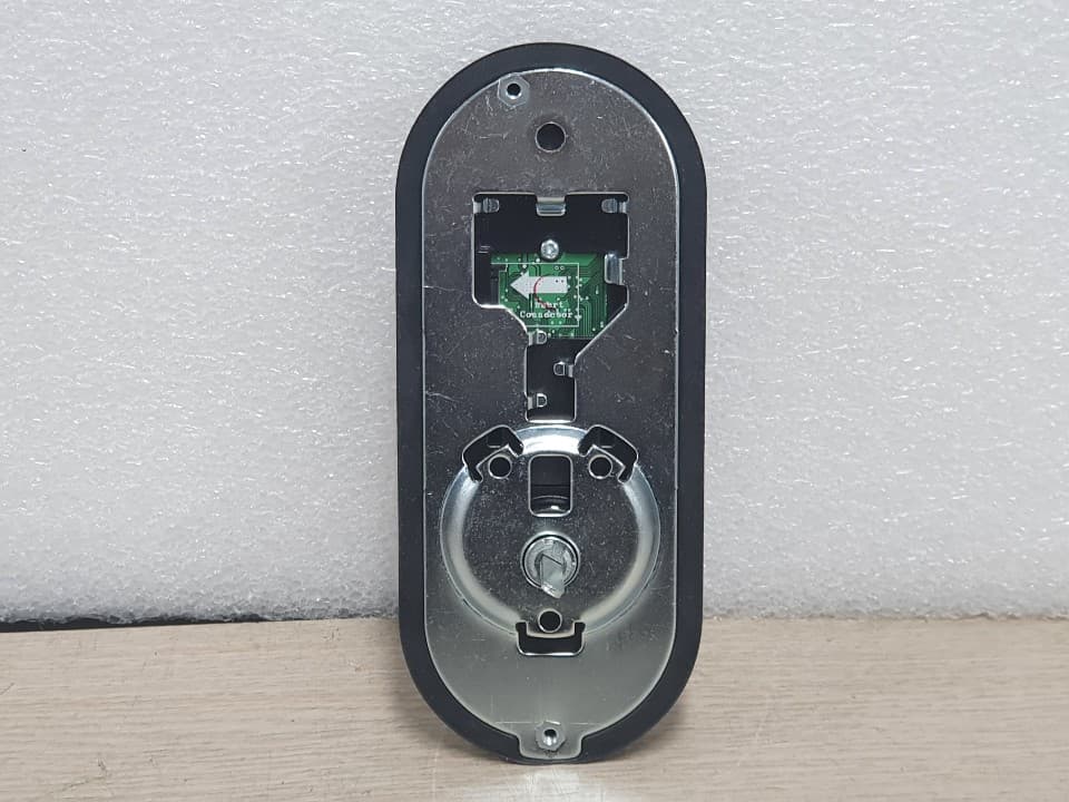
P4YSHP-A30
Jan 16, 2020Digital Doorlock
Equipment Class
DTS - Digital Transmission System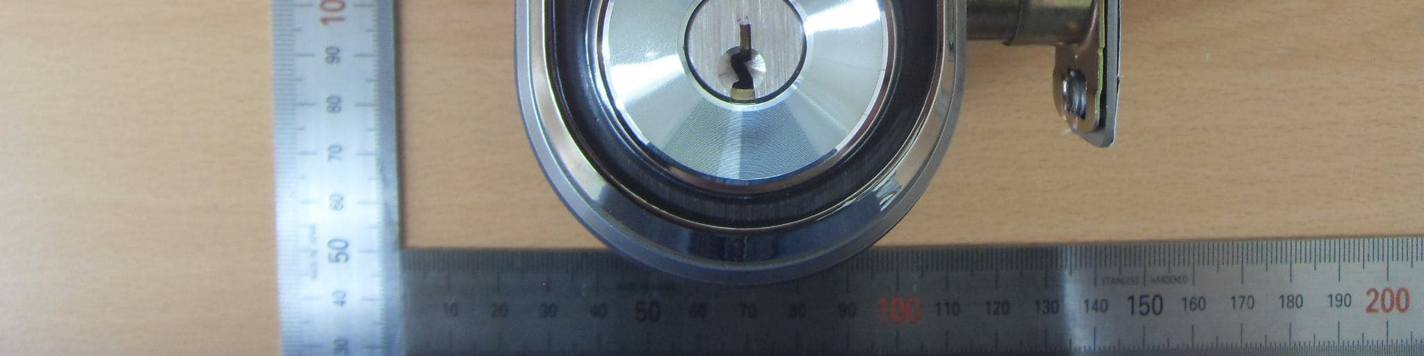
P4YSHP-DS510
Apr 16, 2015Digital door lock
Equipment Class
DXX - Part 15 Low Power Communication Device Transmitter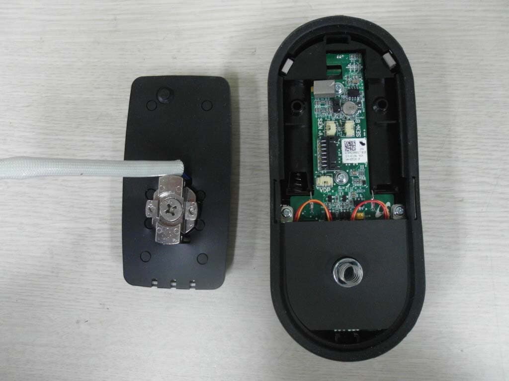
P4Y365PLUS
Mar 26, 2015Digital door lock
Equipment Class
DTS - Digital Transmission System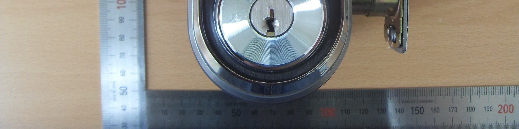
P4YSHN-WDD510
Oct 05, 2014Digital door lock
Equipment Class
DTS - Digital Transmission System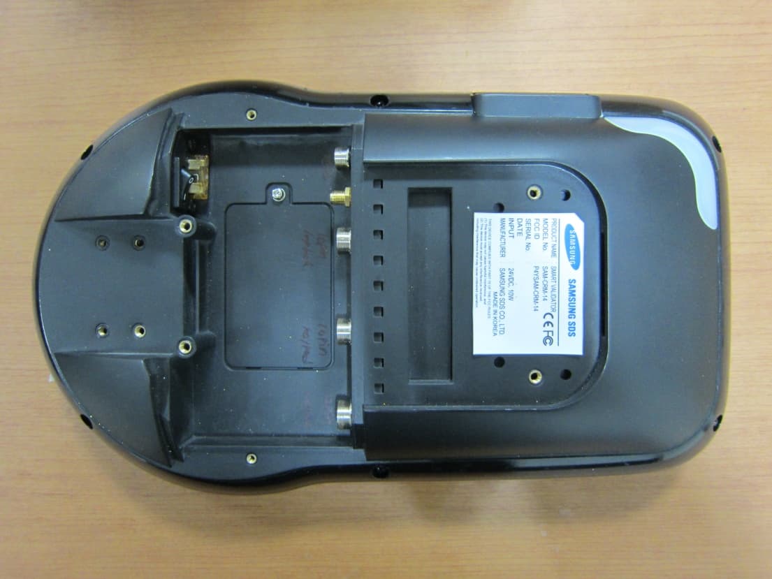
P4YSAM-CRM-14
Jan 19, 2014SMART VALIDATOR
Equipment Class
DSS - Part 15 Spread Spectrum Transmitter