P4YSPS-700BElectric Payment System
Samsung SDS Co., Ltd.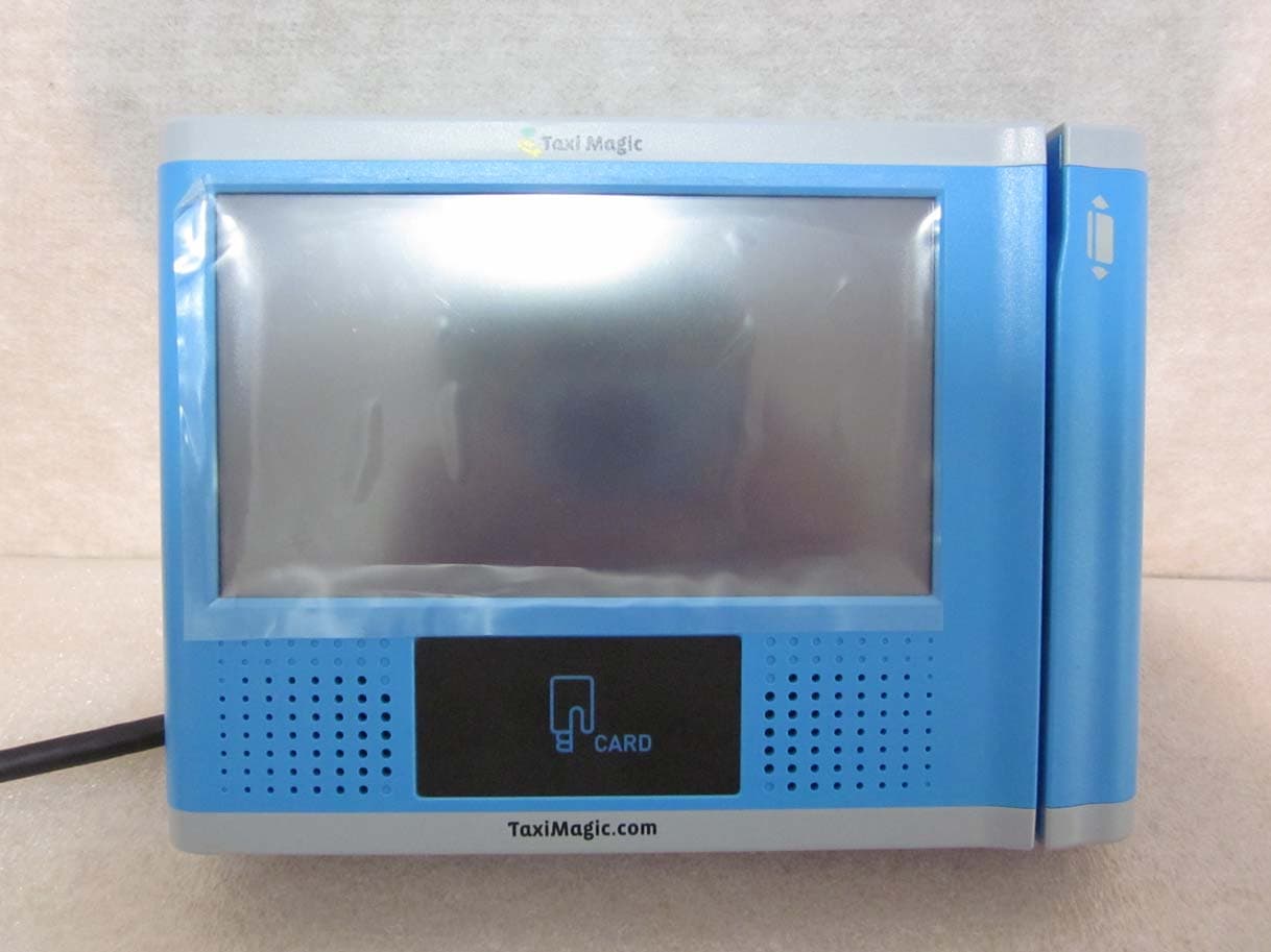
Click to zoom
Application Details
- Equipment Class
- DSS - Part 15 Spread Spectrum Transmitter
- Date of Grant
- May 14, 2012
- Application Purpose
- Original Equipment
- Date of Application
- May 14, 2012
- Equipment Note
- Electric Payment System
- Frequency Range
- 2402.00000000 - 2480.00000000
- Company
- Samsung SDS Co., Ltd.
- Country
- South Korea
Documents & Files
Document Text
Text extracted from the exhibit documents filed with the FCC. Open a document above to read the original.
Users Manual
SPS-700B USER MANUAL SPS-700B User Manual FCCID:P4YSPS-700B Page: 2 / 11 1 PIM CONSTRUCTION SPS-700B User Manual FCCID:P4YSPS-700B Page: 3 / 11 2 SPECIFICATIONS Category Specifications CPU SAMSUNG Arm11 667MHz Memory RAM SDRAM 128M Byte NAND Flash 2G Byte RTC Real Time Clock With Back-up Battery DISPLAY 7" LCD Touch screen , 800 X 480 , 400Nits , Outdoor RF & Smart CARD Card Type MIFARE, ISO14443 A/B, (No support for Contact Smart Card) Reading Distance Max 60mm Security Algorithm Triple-DES MS CARD MSR ISO TRACK 1,2 , Dual Head SAM Slot SIMM Type 4 Slot Video/Audio codec Audio : Wolfson AC 97 Rev 2.2 Codec Video : H.264 , H.263, MPEG4 SP, WMV9 ,VC1, GPU (built in) Sound Speaker 8Ohm 2W X 2/Line Out Audio Jack Interfaces LAN 10/100 Base-T LAN Wifi 802.11 b/g Wireless LAN USB Host 1.1 [2ch] -. 1ch = Expansion( Included Breakout box ) RS232 5ch-5ports -. 1port = GPS only -. 1port = MDT only -. 1port = Taxi Meter only -. 2port = Expansion SD Card Socket SDHC support (32G support) GPS Included ( The 51-channel,5 positioning engine boasts ), cable length : 2.5m RFID RFID (13.56 MHz) Bluetooth Bluetooth standard O/S Embedded Linux 2.6.xx.x Input Power DC 12 V SPS-700B User Manual FCCID:P4YSPS-700B Page: 4 / 11 3 CONTENTS Mounting Bracket PIM M5 x 10mm Set Bolt - 4EA Breakout Box Harness GPS Breakout Box Mounting k PIM GPS Harness SPS-700B User Manual FCCID:P4YSPS-700B Page: 5 / 11 4 INSTALLATION Product outline What is Taxi Magic? Taxi magic is credit card reader and you may pay in a card by yourself after you arrive your destination. [MAIN SCREEN] Wireless LAN GPS Taxi Meter MDT SPS-700B User Manual FCCID:P4YSPS-700B Page: 6 / 11 As you can see above screen, you may see taxi fare on the left/ middle side on the screen. Also, you can find time, temperature and the cab number on the bottom side. And you can select tip amount on the [SETTINGS] menu. [SETTINGS] You may directly select the tip amount ($1, 2$, $3 or other) on the screen as showed on above screen and there are also flat rate mode(10%, 15%, 20%) you may select at ease. [TOTAL PAYMENT INFO] SPS-700B User Manual FCCID:P4YSPS-700B Page: 7 / 11 You can find total amount after choosing the tip as above. And you may continue the payment by pressing [Pay] button if the total amount is correct. Or if the total amount is incorrect, you may return previous screen by pressing CANCEL button. [AUTHORIZING PAYMENT] You will see the message “Please pass your card” after tapping the [Pay] button. Then, please pass your card for authorizing payment. [RECEIPT PRINTOUT] SPS-700B User Manual FCCID:P4YSPS-700B Page: 8 / 11 After your card payment is done correctly, you may get a receipt by choosing “Yes” button on above screen. [HARDWARE SERIAL] You can find each serial information of H/W part [as showed above]. Also, volume control is available. SPS-700B User Manual FCCID:P4YSPS-700B Page: 9 / 11 1. SYSTEM DEVELOPMENT CONECTION DIAGRAM SPS-700B User Manual FCCID:P4YSPS-700B Page: 10 / 11 TAXI TERMINAL 1 : TFTP LCD ( 800 X 480 ) 2 : SPEAKER 3 : RF CARD ANTENNA 4 : MSR SPS-700B User Manual FCCID:P4YSPS-700B Page: 11 / 11 FCC RF INTERFERENCE STATEMENT NOTE : This equipment has been tested and found to comply with the limits for a Class B digital device, pursuant to Part 15 of the FCC Rules. These limits are designed to provide reasonable protection against harmful interference in a residential installation. This equipment generates, uses and can radiate radio frequency energy and, if not installed and used in accordance with the instructions, may cause harmful interference to radio communications. However, there is no guarantee that interference will not occur in a particular installation. If this equipment does cause harmful interference to radio or television reception which can be determined by turning the equipment off and on, the user is encouraged to try to correct the interference by one or more of the following measures. - Reorient or relocate the receiving antenna. - Increase the separation between the equipment and receiver. - Connect the equipment into an outlet on a circuit different from that to which the receiver is connected. - Consult the dealer or an experienced radio, TV technical for help. - Only shielded interface cable should be used. Finally, any changes or modifications to the equipment by the user not expressly approved by the grantee or manufacturer could void the users authority to operate such equipment
Cover Letter(s)
Samsung SDS Co.,Ltd. 707-19, Youksam2-Dong, Kangnam-Gu, Seoul, Korea Tel : +82-2-6484-0557 Fax. +82-2-6484-0688 Federal Communications Commission 7435 Oakland Mills Road Columbia, MD 21046 Gentlemen: This letter is to comply with Sections 0.457 and 0.459 pertaining to confidential material. Samsung SDS Co.,Ltd. would like the following documents regarding this submission for FCC ID : P4YSPS-700B to be kept confidential. 1. Document {Schematics}. 2. Document {Operating Description}. 3. Document{Block Diagram} The above material contains trade secrets or technical data, which would customarily be guarded from competitors. We do not want these documents to be accessible to the general public. Sincerely, Myoung kue Lee / SIE group manager
Cover Letter(s)
Samsung SDS Co.,Ltd. 707-19, Youksam2-Dong, Kangnam-Gu, Seoul, Korea Operating Frequencies Operating Channels 2.4 GHz ~ 2.4835 GHz (13 /79CH) --------------------------------------------------------------------------------------------------------------- Attestation FCC ID : P4YSPS-700B Product : Electric Payment System Model : SPS-700B We don’t provide any controls or software to allow operation outside the USA frequency bands when we sell this product in USA --------------------------------------------------------------------------------------------------------------- May 11, 2012 Myoungkue-Lee / SIE group manager
External Photos
Front of view Rear of view Right of view Left of view Top of view Bottom of view
ID Label/Location Info
ID LABEL LOCATION INFORMATION
Internal Photos
Inner view Main PCB_Front of view Main PCB_Rear of view Sub PCB_Front of view Sub PCB_Rear of view LCD Pannel_Front of view LCD Pannel_Rear of view LCD Pannel_label of view RFID Antenna_Front of view RFID Antenna_Rear of view Antenna
Test Report
Report No. : E12WD-077 Page: 1 of 133 This report shall not be reproduced, in whole or in part without the written approval of Standard Bank Co.,Ltd. Standard Bank Inc. #507,508, Dongyoung Central Tower, 847-2 Kumjung-Dong, Gunpo-Si, Kyunggi-Do, Korea 435-050 Tel: (82) 31-393-9394 Fax: (82) 31-393-9392 www.Standardbank.co.kr Certification of Compliance CFR 47 Part 15 Subpart C Order No. : SB-1204042 Test Report No. : E12WD-077 Applicant : Samsung SDS Co.,Ltd. Address of Applicant : 707-19, Youksam2-Dong, Kangnam-Gu, Seoul, Korea Equipment Under Test (EUT) Kind of Product : Electric Payment System Model Name : SPS-700B FCC ID : P4YSPS-700B Buyer Model(s) : N/A Standards : FCC Part 15 Subpart C (15.247 & 15.225):2010 ANSI C63.4:2009 Date of Receipt : 30 April, 2012 Date of Test : 01 ~ 09 May, 2012 Date of Issue : 11 May, 2012 Test Result : ■Positive □Negative Ji Hwan Kim / Testing By Engineer Chang Woo, Kim / General Manager In the configuration tested, the EUT complied with the standards specified above. Remarks : This report details the results of the testing carried out on one sample, the results contained in this test report do not relate to other samples of the same product. The manufacturer should ensure that all products in series production are in conformity with the product sample detailed in this report. This report may only be reproduced and distributed in full. If the product in this report is used in any configuration other than that detailed in the report, the manufacturer must ensure the new system complies with all relevant standards. Report No. : E12WD-077 Page: 2 of 133 This report shall not be reproduced, in whole or in part without the written approval of Standard Bank Co.,Ltd. Standard Bank Inc. #507,508, Dongyoung Central Tower, 847-2 Kumjung-Dong, Gunpo-Si, Kyunggi-Do, Korea 435-050 Tel: (82) 31-393-9394 Fax: (82) 31-393-9392 www.Standardbank.co.kr Contents 1. GENERAL INFORMATION .............................................................. 6 1.1 INFORMATION OF TEST LABORATORY. ....................................................... 6 1.2 DESCRIPTION OF TEST .................................................................... 7 1.3 MEASUREMENT UNCERTAINTY CALCULATIONS ............................................... 10 1.4 MANUFACTURER INFORMATION ........................................................... 11 1.5 GENERAL DESCRIPTION OF EUT ........................................................... 11 1.6 DETAILS OF EUT ....................................................................... 11 1.7 DESCRIPTION OF SUPPORT UNITS .......................................................... 12 N OTE : .................................................................................. 12 1.8 CABLE LIST ........................................................................... 13 1.10 TEST SET-UP CONFIGURATION ........................................................... 14 1.11 TEST METHODOLOGY AND CONFIGURATION ................................................ 14 1.12 STANDARDS APPLICABLE FOR TESTING .................................................... 14 2. SUMMARY ........................................................................... 15 3. EQUIPMENT UNDER TEST CONDITION A(WIFI OPERATION) ............................ 17 3.1 RADIETED EMISSION ................................................................ 17 3.1.1 TEST INSTRUMENTS ................................................................... 17 3.1.2 TEST AREA .......................................................................... 17 3.1.3 OPERATION OF EUT ................................................................... 17 3.1.4 TEST DATE .......................................................................... 17 3.1.5 RADIATED EMISSION LIMIT ............................................................. 18 3.1.5.1 RADIATED EMISSION RESULT(30 TO 1000 MHZ) ........................................... 19 3.1.5.2 FUNDAMENTAL & HARMONICS RADIATED EMISSION RESULT(1 TO 26 GHZ) ..................... 25 3.3 PEAK POWER OUTPUT ............................................................... 49 3.3.1 TEST INSTRUMENTS ................................................................... 49 3.3.2 LIMIT .............................................................................. 49 3.3.3 TEST CONFIGURATION ................................................................. 49 3.3.4 TEST PROCEDURE ..................................................................... 49 3.3.5 PEAK POWER TEST RESULT ............................................................. 49 3.4 BAND EDGE ......................................................................... 54 3.4.1 TEST INSTRUMENTS ................................................................... 54 3.4.2 LIMIT .............................................................................. 54 Report No. : E12WD-077 Page: 3 of 133 This report shall not be reproduced, in whole or in part without the written approval of Standard Bank Co.,Ltd. Standard Bank Inc. #507,508, Dongyoung Central Tower, 847-2 Kumjung-Dong, Gunpo-Si, Kyunggi-Do, Korea 435-050 Tel: (82) 31-393-9394 Fax: (82) 31-393-9392 www.Standardbank.co.kr 3.4.3 TEST CONFIGURATION ................................................................. 55 3.4.4 TEST PROCEDURE ..................................................................... 55 3.4.5 TEST RESULT METHOD OF BAND EDGE TEST RESULT OF RADIATED TEST. ......................... 55 3.4.6 BAND EDGE TEST RESULT .............................................................. 56 3.5 6 DB BAND .......................................................................... 64 3.5.1 TEST INSTRUMENTS ................................................................... 64 3.5.2 LIMIT .............................................................................. 64 3.5.3 TEST CONFIGURATION ................................................................. 64 3.5.4 TEST PROCEDURE ............…
Text truncated - open the document above for the full version.
Test Setup Photos
Below 30 MHz 30 to 1000 MHz Above 1 GHz Conducted Test
Contact Information
Applicant
Myoung Kue Lee(Advisory Engineer)
Test Firm
Standard bank Co., LTD.Sang Hee Lee
Technical Specifications
| # | Rule Parts | Frequency Range | Power Output |
|---|---|---|---|
| 1 | 15C | 2.40 GHz - 2.48 GHz | 5.89 mW |
Other Applications from Samsung SDS Co., Ltd.
P4YSHP-A30
Jan 16, 2020Digital Doorlock
Equipment Class
DTS - Digital Transmission System
P4YSHP-DS510
Apr 16, 2015Digital door lock
Equipment Class
DXX - Part 15 Low Power Communication Device Transmitter
P4Y365PLUS
Mar 26, 2015Digital door lock
Equipment Class
DTS - Digital Transmission System
P4YSHN-WDD510
Oct 05, 2014Digital door lock
Equipment Class
DTS - Digital Transmission System
P4YSAM-CRM-14
Jan 19, 2014SMART VALIDATOR
Equipment Class
DSS - Part 15 Spread Spectrum Transmitter