PDCILM-2500iLM 2500 Internet Location Modem
At Road, Incorporated
Click to zoom
Application Details
- Equipment Class
- TNB - Licensed Non-Broadcast Station Transmitter
- Date of Grant
- Feb 25, 2001
- Application Purpose
- Original Equipment
- Date of Application
- Nov 21, 2000
- Equipment Note
- iLM 2500 Internet Location Modem
- Frequency Range
- 824.04000000 - 848.97000000
- Company
- At Road, Incorporated
- Country
- United States
Documents & Files
Document Text
Text extracted from the exhibit documents filed with the FCC. Open a document above to read the original.
Users Manual
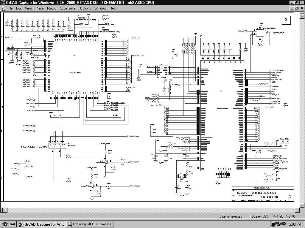
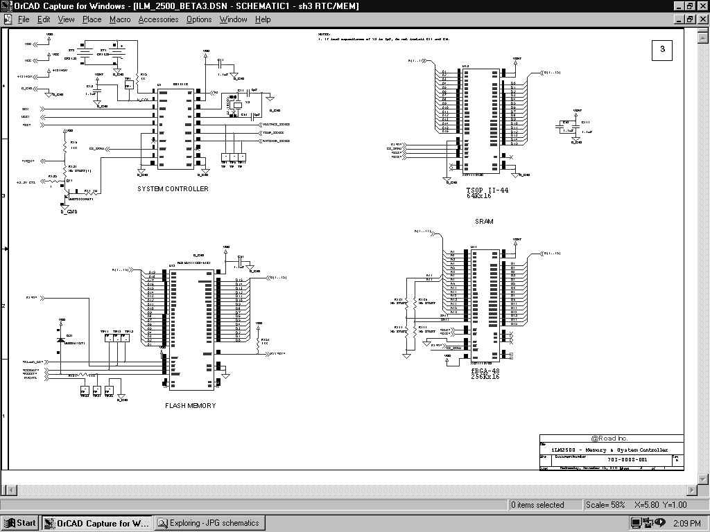
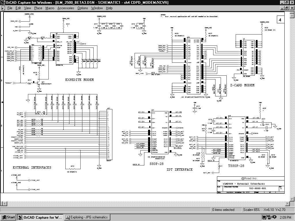
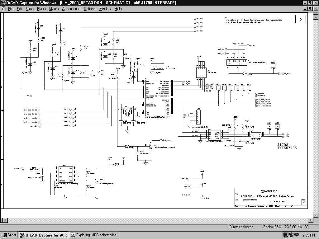
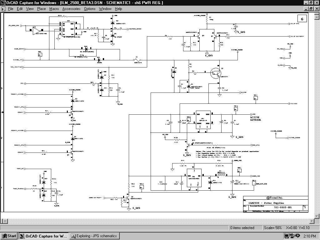
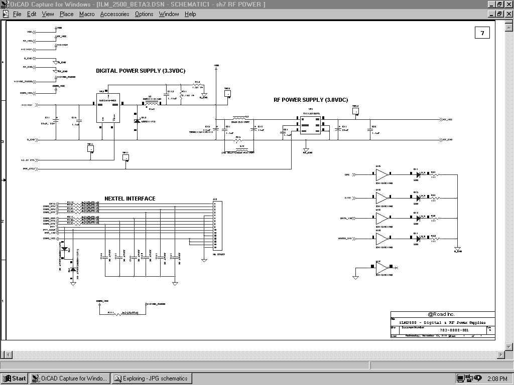
iLM 2500 Operational Description The iLM 2500 Internet Location Modem combines GPS with a wireless data modem to provide vehicle location specific information. The intended use is to monitor location, speed and travel direction of vehicles. It is also designed to monitor PTO and activity based events such as ignition status, door open/close and tow lifts. It provides a serial interface for computers and peripheral devices like a printer, smart card reader, bar code scanner and temperature sensor. Automatic Vehicle Location (AVL) System Diagram System Description The iLM2500 has a GPS receiver, which receives location specific information from satellites. The GPS engine translates the receiving signal into data information and passes it on to the CPU. The CPU computes vehicle location, based on the information received. The location data is sent to the Rover Server/Database over the CDPD network. The information is retrieved via the Internet. The data is updated at intervals defined by the user. Hardware Description The Main components used in iLM2500 design include Motorola’s MC68331 processor, Flash, SRAM, Vista chip set from @Road, RTC/System Controller, and various different 3 rd party CDPD OEM modules. Power to the system is drawn from a vehicles +12VDC source. A few voltage regulators use this source to generate power and supply it to different areas on the PCB. The iLM2500 has a backup battery feature. The backup battery kicks in automatically when the main power falls below operating voltage or is absent. The power supplied to external devices via Data Port 1 and Data Port 2 can be switched ON/OFF by the CPU. This was added to enhance power management. System Architecture CPU Motorola’s MC68331 processor is used as the main controller of the system. It runs at 16Mhz, which is generated from an external 32.768Khz crystal. The CPU interfaces with flash memory, SRAM, GPS Asic and other I/Os in the system. An internal watchdog timer is used to generate the system reset. Flash Memory Flash ROM is used to store all the firmware and other information such as manufactures ID, user code, and other permanent codes. The board layout can be configured to use 4Mbit or 8Mbit Flash. Flash Memory contains the following key components: 1. Boot block (OTAP capable in 96 and above firmware version) 2. Configuration data (IP addresses, device ID etc.) 3. GPS lookup tables. 4. Main program executable. SRAM SRAM is used to store all volatile and non-volatile data including PVT (Position, Velocity, Time) points and retain the data through use of a small battery. Vista GPS Chipset An @Road proprietary chipset comprised of two chips, GPS Signal Processing ASIC (VGP-12) and RF ASIC (VRF-12). GPS Signal Processing ASIC VGP-12 is the GPS Digital ASIC that combines twelve satellite correlator channels with other GPS system control peripherals. VGP-12 is designed to work with L1-CA dual bit down converter RF ASIC chip, VRF-12 by @Road. VGP-12 is designed to process up to 4 VRF-12 down converted signals for applications requiring multiple antenna connections. Concurrent processing of multiple antenna signals: a) Delta phase measurements between down converted signals. b) Independently down converted signal processing, c) Cross strapping for redundancy. VGP-12 contains six types of functional blocks: A CPU interface, GPS clock controller, GPS correlator channels with their common control logic, receiver magnitude gain control, 8-bit parallel port and two serial ports (UART). The VGP-12 device is packaged in 100-pin PQFP and operates from 2.7 to 3.7 volt supply. RF ASIC VRF-12 has an integrated dual conversion front end for a Global Positioning System (GPS) receiver application. The input is L1 (1575.42 Mhz) GPS signal. Output is a down converted, band pass 2-bit quantized signal, ready for digital processing. VRF-12 is a dual conversion super-heterodyne receiver featuring an on-chip low noise amplifier (LNA), an image-reject front end, voltage-controlled-oscillator (VCO) with on-chip resonator, phase lock loop (PLL) synthesizer, automatic gain control (AGC), reference oscillator, 2-bit A/D and power control. VRF-12 device is packaged in 48-pin TQFP and operates from 2.7 to 3.7 volt supply. CDPD Modem The CDPD modem is used to transmit location specific information from the iLM2500 to @Road’s Server. The data is sent over periodic intervals defined by users and governed by different cost plans. The CDPD modem interface is through the UART from the Digital ASIC, VGP-12. The supply power to the modem can be turned ON/OFF via CPU control. RTC and System Controller A DS1670E IC from Dallas Semiconductor is used for real time clock and NVRAM control, including automatic battery backup. It also has three A/D inputs. The CPU uses an 8-bit A/D Converter to monitor supply voltage, temperature and GPS antenna. External Interfaces There are two external interface connectors available. One 26 pin for data and one 16 pin for power and high current I/O interface. The supported interfaces are Data Port1, Data Port2, PTO I/Os, Relay Drivers, Nextel Modem, and power I/Os. There are also two RF connectors for GPS and CDPD Modem antennas. Data Port1 Data Port1 is solely used for the iDT, manufacturing, configuring, and debugging. Data Port2 Data Port2 can be treated as the auxiliary data port. It interfaces with external devices such as a temperature sensor, smart card reader, printer, barcode scanner and magnetic stripe reader. PTO I/Os These I/Os allow a customer to monitor up to 4 contact-based switch events. The iLM can be programmed to transmit additional points when a switch transition occurs. Each time a switch transition, ON!OFF or OFF!ON occurs, an update is transmitted to the server. Relay Drivers There are two +12VDC relay drivers that can be used to turn ON/OFF the external relays. Nextel Modem Allows the user to interface an iLM2500 with an iDEN700 Nextel phone. The phone is data capable for communicating with …
Text truncated - open the document above for the full version.
Users Manual
iLM 2500 Operational Description The iLM 2500 Internet Location Modem combines GPS with a wireless data modem to provide vehicle location specific information. The intended use is to monitor location, speed and travel direction of vehicles. It is also designed to monitor PTO and activity based events such as ignition status, door open/close and tow lifts. It provides a serial interface for computers and peripheral devices like a printer, smart card reader, bar code scanner and temperature sensor. Automatic Vehicle Location (AVL) System Diagram System Description The iLM2500 has a GPS receiver, which receives location specific information from satellites. The GPS engine translates the receiving signal into data information and passes it on to the CPU. The CPU computes vehicle location, based on the information received. The location data is sent to the Rover Server/Database over the CDPD network. The information is retrieved via the Internet. The data is updated at intervals defined by the user. Hardware Description The Main components used in iLM2500 design include Motorola’s MC68331 processor, Flash, SRAM, Vista chip set from @Road, RTC/System Controller, and various different 3 rd party CDPD OEM modules. Power to the system is drawn from a vehicles +12VDC source. A few voltage regulators use this source to generate power and supply it to different areas on the PCB. The iLM2500 has a backup battery feature. The backup battery kicks in automatically when the main power falls below operating voltage or is absent. The power supplied to external devices via Data Port 1 and Data Port 2 can be switched ON/OFF by the CPU. This was added to enhance power management. System Architecture CPU Motorola’s MC68331 processor is used as the main controller of the system. It runs at 16Mhz, which is generated from an external 32.768Khz crystal. The CPU interfaces with flash memory, SRAM, GPS Asic and other I/Os in the system. An internal watchdog timer is used to generate the system reset. Flash Memory Flash ROM is used to store all the firmware and other information such as manufactures ID, user code, and other permanent codes. The board layout can be configured to use 4Mbit or 8Mbit Flash. Flash Memory contains the following key components: 1. Boot block (OTAP capable in 96 and above firmware version) 2. Configuration data (IP addresses, device ID etc.) 3. GPS lookup tables. 4. Main program executable. SRAM SRAM is used to store all volatile and non-volatile data including PVT (Position, Velocity, Time) points and retain the data through use of a small battery. Vista GPS Chipset An @Road proprietary chipset comprised of two chips, GPS Signal Processing ASIC (VGP-12) and RF ASIC (VRF-12). GPS Signal Processing ASIC VGP-12 is the GPS Digital ASIC that combines twelve satellite correlator channels with other GPS system control peripherals. VGP-12 is designed to work with L1-CA dual bit down converter RF ASIC chip, VRF-12 by @Road. VGP-12 is designed to process up to 4 VRF-12 down converted signals for applications requiring multiple antenna connections. Concurrent processing of multiple antenna signals: a) Delta phase measurements between down converted signals. b) Independently down converted signal processing, c) Cross strapping for redundancy. VGP-12 contains six types of functional blocks: A CPU interface, GPS clock controller, GPS correlator channels with their common control logic, receiver magnitude gain control, 8-bit parallel port and two serial ports (UART). The VGP-12 device is packaged in 100-pin PQFP and operates from 2.7 to 3.7 volt supply. RF ASIC VRF-12 has an integrated dual conversion front end for a Global Positioning System (GPS) receiver application. The input is L1 (1575.42 Mhz) GPS signal. Output is a down converted, band pass 2-bit quantized signal, ready for digital processing. VRF-12 is a dual conversion super-heterodyne receiver featuring an on-chip low noise amplifier (LNA), an image-reject front end, voltage-controlled-oscillator (VCO) with on-chip resonator, phase lock loop (PLL) synthesizer, automatic gain control (AGC), reference oscillator, 2-bit A/D and power control. VRF-12 device is packaged in 48-pin TQFP and operates from 2.7 to 3.7 volt supply. CDPD Modem The CDPD modem is used to transmit location specific information from the iLM2500 to @Road’s Server. The data is sent over periodic intervals defined by users and governed by different cost plans. The CDPD modem interface is through the UART from the Digital ASIC, VGP-12. The supply power to the modem can be turned ON/OFF via CPU control. RTC and System Controller A DS1670E IC from Dallas Semiconductor is used for real time clock and NVRAM control, including automatic battery backup. It also has three A/D inputs. The CPU uses an 8-bit A/D Converter to monitor supply voltage, temperature and GPS antenna. External Interfaces There are two external interface connectors available. One 26 pin for data and one 16 pin for power and high current I/O interface. The supported interfaces are Data Port1, Data Port2, PTO I/Os, Relay Drivers, Nextel Modem, and power I/Os. There are also two RF connectors for GPS and CDPD Modem antennas. Data Port1 Data Port1 is solely used for the iDT, manufacturing, configuring, and debugging. Data Port2 Data Port2 can be treated as the auxiliary data port. It interfaces with external devices such as a temperature sensor, smart card reader, printer, barcode scanner and magnetic stripe reader. PTO I/Os These I/Os allow a customer to monitor up to 4 contact-based switch events. The iLM can be programmed to transmit additional points when a switch transition occurs. Each time a switch transition, ON!OFF or OFF!ON occurs, an update is transmitted to the server. Relay Drivers There are two +12VDC relay drivers that can be used to turn ON/OFF the external relays. Nextel Modem (Optional) Allows the user to interface an iLM2500 with an iDEN700 Nextel phone. The phone is data capable for communic…
Text truncated - open the document above for the full version.
Users Manual
iLM 2500 Operational Description The iLM 2500 Internet Location Modem combines GPS with a wireless data modem to provide vehicle location specific information. The intended use is to monitor location, speed and travel direction of vehicles. It is also designed to monitor PTO and activity based events such as ignition status, door open/close and tow lifts. It provides a serial interface for computers and peripheral devices like a printer, smart card reader, bar code scanner and temperature sensor. Automatic Vehicle Location (AVL) System Diagram System Description The iLM2500 has a GPS receiver, which receives location specific information from satellites. The GPS engine translates the receiving signal into data information and passes it on to the CPU. The CPU computes vehicle location, based on the information received. The location data is sent to the Rover Server/Database over the CDPD network. The information is retrieved via the Internet. The data is updated at intervals defined by the user. Hardware Description The Main components used in iLM2500 design include Motorola’s MC68331 processor, Flash, SRAM, Vista chip set from @Road, RTC/System Controller, and various different 3 rd party CDPD OEM modules. Power to the system is drawn from a vehicles +12VDC source. A few voltage regulators use this source to generate power and supply it to different areas on the PCB. The iLM2500 has a backup battery feature. The backup battery kicks in automatically when the main power falls below operating voltage or is absent. The power supplied to external devices via Data Port 1 and Data Port 2 can be switched ON/OFF by the CPU. This was added to enhance power management. System Architecture CPU Motorola’s MC68331 processor is used as the main controller of the system. It runs at 16Mhz, which is generated from an external 32.768Khz crystal. The CPU interfaces with flash memory, SRAM, GPS Asic and other I/Os in the system. An internal watchdog timer is used to generate the system reset. Flash Memory Flash ROM is used to store all the firmware and other information such as manufactures ID, user code, and other permanent codes. The board layout can be configured to use 4Mbit or 8Mbit Flash. Flash Memory contains the following key components: 1. Boot block (OTAP capable in 96 and above firmware version) 2. Configuration data (IP addresses, device ID etc.) 3. GPS lookup tables. 4. Main program executable. SRAM SRAM is used to store all volatile and non-volatile data including PVT (Position, Velocity, Time) points and retain the data through use of a small battery. Vista GPS Chipset An @Road proprietary chipset comprised of two chips, GPS Signal Processing ASIC (VGP-12) and RF ASIC (VRF-12). GPS Signal Processing ASIC VGP-12 is the GPS Digital ASIC that combines twelve satellite correlator channels with other GPS system control peripherals. VGP-12 is designed to work with L1-CA dual bit down converter RF ASIC chip, VRF-12 by @Road. VGP-12 is designed to process up to 4 VRF-12 down converted signals for applications requiring multiple antenna connections. Concurrent processing of multiple antenna signals: a) Delta phase measurements between down converted signals. b) Independently down converted signal processing, c) Cross strapping for redundancy. VGP-12 contains six types of functional blocks: A CPU interface, GPS clock controller, GPS correlator channels with their common control logic, receiver magnitude gain control, 8-bit parallel port and two serial ports (UART). The VGP-12 device is packaged in 100-pin PQFP and operates from 2.7 to 3.7 volt supply. RF ASIC VRF-12 has an integrated dual conversion front end for a Global Positioning System (GPS) receiver application. The input is L1 (1575.42 Mhz) GPS signal. Output is a down converted, band pass 2-bit quantized signal, ready for digital processing. VRF-12 is a dual conversion super-heterodyne receiver featuring an on-chip low noise amplifier (LNA), an image-reject front end, voltage-controlled-oscillator (VCO) with on-chip resonator, phase lock loop (PLL) synthesizer, automatic gain control (AGC), reference oscillator, 2-bit A/D and power control. VRF-12 device is packaged in 48-pin TQFP and operates from 2.7 to 3.7 volt supply. CDPD Modem The CDPD modem is used to transmit location specific information from the iLM2500 to @Road’s Server. The data is sent over periodic intervals defined by users and governed by different cost plans. The CDPD modem interface is through the UART from the Digital ASIC, VGP-12. The supply power to the modem can be turned ON/OFF via CPU control. RTC and System Controller A DS1670E IC from Dallas Semiconductor is used for real time clock and NVRAM control, including automatic battery backup. It also has three A/D inputs. The CPU uses an 8-bit A/D Converter to monitor supply voltage, temperature and GPS antenna. External Interfaces There are two external interface connectors available. One 26 pin for data and one 16 pin for power and high current I/O interface. The supported interfaces are Data Port1, Data Port2, PTO I/Os, Relay Drivers, Nextel Modem, and power I/Os. There are also two RF connectors for GPS and CDPD Modem antennas. Data Port1 Data Port1 is solely used for the iDT, manufacturing, configuring, and debugging. Data Port2 Data Port2 can be treated as the auxiliary data port. It interfaces with external devices such as a temperature sensor, smart card reader, printer, barcode scanner and magnetic stripe reader. PTO I/Os These I/Os allow a customer to monitor up to 4 contact-based switch events. The iLM can be programmed to transmit additional points when a switch transition occurs. Each time a switch transition, ON!OFF or OFF!ON occurs, an update is transmitted to the server. Relay Drivers There are two +12VDC relay drivers that can be used to turn ON/OFF the external relays. Nextel Modem (Optional) Allows the user to interface an iLM2500 with an iDEN700 Nextel phone. The phone is data capable for communic…
Text truncated - open the document above for the full version.
Cover Letter(s)
__________________________USA Facility Europe Facility 9959 Calaveras Road, PO Box 543 Robert -Bosch-St raße 2-4 Sunol, CA 94586-0543 61184 Karben, Germany Tel: (925) 862-2944 Tel: (011) 49-6039-9182-0 Fax: (925) 862-9013 Fax: (011) 49-6039-9182-29 E-mail: it [email protected] E-mail: [email protected] International Technology Company (ITC) over 20 years experience in compliance testing and engineering consulting services 9959 Calaveras Road Box 543, Sunol, CA 94586-0543 phone: (925) 862-2944 • fax: (925) 862-9013 • internet: www.itcemc.com ———————— EN 45001, NVLAP and VCCI Accredited Laboratory ———————————— Certified by Rockford Engineering Services GmbH (A Competent Body) Date: Monday November 27, 2000 Attn.: Authorization and Standards Division Federal Communications Commission Authorization and Evaluation Division 7435 Oakland Mills Road Columbia, MD 21046 File Number: FCC ID: PDCILM-2500 Subject: Application for Grant of Equipment Authorization To Whom It May Concern, The enclosed documents constitute a formal submittal and application for a Grant of Equipment Authorization pursuant to Part 22.901(d), of the Rules and Regulations of the FCC. The data in this report demonstrate that the equipment tested complies with the FCC Part 15, SubPart B, Open Field Radiated Emissions Test limits for Class B devices. The CDPD Modem contained in the device; which falls under Part 22.901(d) is manufactured by Novaltel Wireless and already certified under FCC ID: NBZNRM-6832. Application and report submitted on behalf of At Road, Inc., was prepared by International Technology Company (ITC). If there are any questions or if further information is needed, please call us at (925) 862-2944 or fax (925) 862-9013. Thank you. ITC __________________________USA Facility Europe Facility 9959 Calaveras Road, PO Box 543 Robert -Bosch-St raße 2-4 Sunol, CA 94586-0543 61184 Karben, Germany Tel: (925) 862-2944 Tel: (011) 49-6039-9182-0 Fax: (925) 862-9013 Fax: (011) 49-6039-9182-29 E-mail: it [email protected] E-mail: [email protected] Yours sincerely, Miss Olufunke Aderibigbe Documentation/Publication International Technology Company (ITC). [Sunol-CA]
External Photos
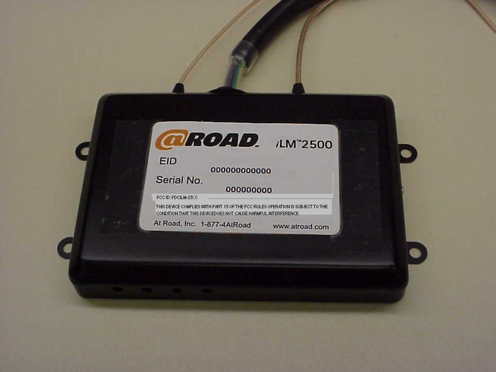
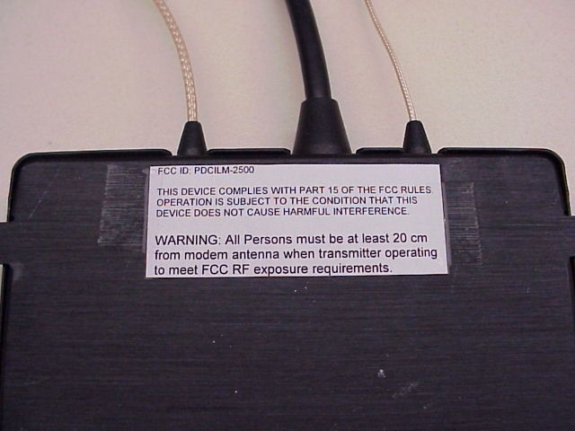
EUT Photographs EUT Layout External Layout External Layout
Internal Photos
Internal Photographs Internal Layout Internal Layout
Operational Description
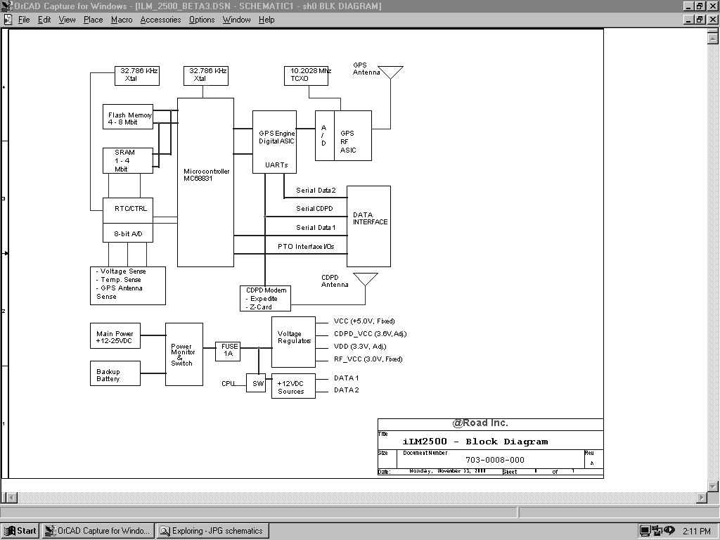
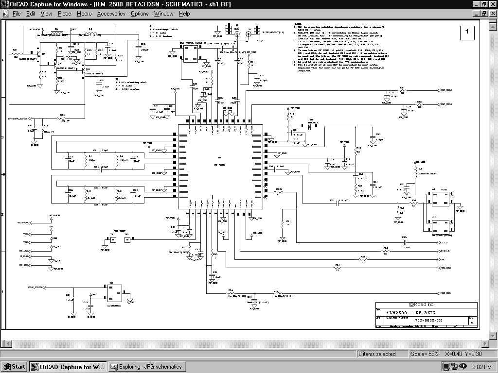
iLM 2500 Operational Description The iLM 2500 Internet Location Modem combines GPS with a wireless data modem to provide vehicle location specific information. The intended use is to monitor location, speed and travel direction of vehicles. It is also designed to monitor PTO and activity based events such as ignition status, door open/close and tow lifts. It provides a serial interface for computers and peripheral devices like a printer, smart card reader, bar code scanner and temperature sensor. Automatic Vehicle Location (AVL) System Diagram System Description The iLM2500 has a GPS receiver, which receives location specific information from satellites. The GPS engine translates the receiving signal into data information and passes it on to the CPU. The CPU computes vehicle location, based on the information received. The location data is sent to the Rover Server/Database over the CDPD network. The information is retrieved via the Internet. The data is updated at intervals defined by the user. Hardware Description The Main components used in iLM2500 design include Motorola’s MC68331 processor, Flash, SRAM, Vista chip set from @Road, RTC/System Controller, and various different 3 rd party CDPD OEM modules. Power to the system is drawn from a vehicles +12VDC source. A few voltage regulators use this source to generate power and supply it to different areas on the PCB. The iLM2500 has a backup battery feature. The backup battery kicks in automatically when the main power falls below operating voltage or is absent. The power supplied to external devices via Data Port 1 and Data Port 2 can be switched ON/OFF by the CPU. This was added to enhance power management. System Architecture CPU Motorola’s MC68331 processor is used as the main controller of the system. It runs at 16Mhz, which is generated from an external 32.768Khz crystal. The CPU interfaces with flash memory, SRAM, GPS Asic and other I/Os in the system. An internal watchdog timer is used to generate the system reset. Flash Memory Flash ROM is used to store all the firmware and other information such as manufactures ID, user code, and other permanent codes. The board layout can be configured to use 4Mbit or 8Mbit Flash. Flash Memory contains the following key components: 1. Boot block (OTAP capable in 96 and above firmware version) 2. Configuration data (IP addresses, device ID etc.) 3. GPS lookup tables. 4. Main program executable. SRAM SRAM is used to store all volatile and non-volatile data including PVT (Position, Velocity, Time) points and retain the data through use of a small battery. Vista GPS Chipset An @Road proprietary chipset comprised of two chips, GPS Signal Processing ASIC (VGP-12) and RF ASIC (VRF-12). GPS Signal Processing ASIC VGP-12 is the GPS Digital ASIC that combines twelve satellite correlator channels with other GPS system control peripherals. VGP-12 is designed to work with L1-CA dual bit down converter RF ASIC chip, VRF-12 by @Road. VGP-12 is designed to process up to 4 VRF-12 down converted signals for applications requiring multiple antenna connections. Concurrent processing of multiple antenna signals: a) Delta phase measurements between down converted signals. b) Independently down converted signal processing, c) Cross strapping for redundancy. VGP-12 contains six types of functional blocks: A CPU interface, GPS clock controller, GPS correlator channels with their common control logic, receiver magnitude gain control, 8-bit parallel port and two serial ports (UART). The VGP-12 device is packaged in 100-pin PQFP and operates from 2.7 to 3.7 volt supply. RF ASIC VRF-12 has an integrated dual conversion front end for a Global Positioning System (GPS) receiver application. The input is L1 (1575.42 Mhz) GPS signal. Output is a down converted, band pass 2-bit quantized signal, ready for digital processing. VRF-12 is a dual conversion super-heterodyne receiver featuring an on-chip low noise amplifier (LNA), an image-reject front end, voltage-controlled-oscillator (VCO) with on-chip resonator, phase lock loop (PLL) synthesizer, automatic gain control (AGC), reference oscillator, 2-bit A/D and power control. VRF-12 device is packaged in 48-pin TQFP and operates from 2.7 to 3.7 volt supply. CDPD Modem The CDPD modem is used to transmit location specific information from the iLM2500 to @Road’s Server. The data is sent over periodic intervals defined by users and governed by different cost plans. The CDPD modem interface is through the UART from the Digital ASIC, VGP-12. The supply power to the modem can be turned ON/OFF via CPU control. RTC and System Controller A DS1670E IC from Dallas Semiconductor is used for real time clock and NVRAM control, including automatic battery backup. It also has three A/D inputs. The CPU uses an 8-bit A/D Converter to monitor supply voltage, temperature and GPS antenna. External Interfaces There are two external interface connectors available. One 26 pin for data and one 16 pin for power and high current I/O interface. The supported interfaces are Data Port1, Data Port2, PTO I/Os, Relay Drivers, Nextel Modem, and power I/Os. There are also two RF connectors for GPS and CDPD Modem antennas. Data Port1 Data Port1 is solely used for the iDT, manufacturing, configuring, and debugging. Data Port2 Data Port2 can be treated as the auxiliary data port. It interfaces with external devices such as a temperature sensor, smart card reader, printer, barcode scanner and magnetic stripe reader. PTO I/Os These I/Os allow a customer to monitor up to 4 contact-based switch events. The iLM can be programmed to transmit additional points when a switch transition occurs. Each time a switch transition, ON!OFF or OFF!ON occurs, an update is transmitted to the server. Relay Drivers There are two +12VDC relay drivers that can be used to turn ON/OFF the external relays. Nextel Modem Allows the user to interface an iLM2500 with an iDEN700 Nextel phone. The phone is data capable for communicating with …
Text truncated - open the document above for the full version.
RF Exposure Info
Prepared By: International Technology Company 9959Calaveras Road, Box 543 Sunol, CA 94586-0543 Tel: 925-862-2944 Fax: 925-862-9013 Email: [email protected] Web: www.itcemc.com Applicant:At Road, Incorporated FCC ID:PDCILM-2500 Confirmation NumberEA99345 Test: RF Power Output Radiated Specification: 47 CFR 2.1046(a) Guide: EIA/IS-19-B-1988 TIA/EIA/IS-137-A-1996 Radiated Measurement Procedure The EUT was placed on an open-field site and its radiated field strength at a known distance was measured by means of a spectrum analyzer. Using freshly charged batteries, data packets were transmitted numerous times, while the receiving antenna placed 3 meters from the transmit antenna captured the signal power. Equivalent loading was calculated from the equation. Only 3 data frequencies are used for ERP Calculation as represented in this rep ort. P t = ((E x R) 2 /49.2) watts, where R = 3m. E = Signal amplitude in v/m Measurement accuracy is +1.5dB Frequency MHzdBuV/ m Corr. Factor dBuV/m Corr. Amp. dBuV/m uV/m @ 3m V/m @ 3m ERP Watts 847.04000072.7225.66 98.38829850.08290.005 845.40300073.0326.90 99.93991970.09910.006 848.97000072.1525.61 97.76772680.07720.005 20 Log X=Z uV/mLog X=Z uV/m 20 X=10 (Z uV/m)/20 EUT CPDP Modem Control Battery 3m Spectrum Analyzer Prepared By: International Technology Company 9959Calaveras Road, Box 543 Sunol, CA 94586-0543 Tel: 925-862-2944 Fax: 925-862-9013 Email: [email protected] Web: www.itcemc.com Prepared By: International Technology Company 9959Calaveras Road, Box 543 Sunol, CA 94586-0543 Tel: 925-862-2944 Fax: 925-862-9013 Email: [email protected] Web: www.itcemc.com RF Safety Exposure per FCC Requirement The Maximum Permissible Exposure (MPE) distance per ANSI C95.1 table 2 for uncontrolled cellular phone environment is f(MHz)/1500 [mW/cm 2 ]. The numeric value of the gain for both antennas is 2(3dBi). Therefore the power density is 850mW x 2.0/(4 π r 2 ) =848/1500[mW/cm 2 ] r = [ (848MHz/1500mW/cm 2 ) (4 π ) / 850mW] ½ r = 4.1cm Therefore, the maximum calculated MPE distance r is 4.1cm. The installation instructions shall indicate that at least 6.1cm (4.1 + 2 margin) separation shall be provided between the antennas and the people. Prepared By: Michael Gbadebo, PE Chief Engineer
Test Report
FCC Part 15 Sub-Part B Declaration of Conformity Report on iLM 2500 Internet Location Modem model iLM 2500 provided for evaluation by At Road, Incorporated 47370 Fremont Boulevard Fremont, California 94538 USA tests and evaluation performed by International Technology Company (ITC) 9959 Calaveras Road, Box 543 Sunol, California 94586-0543 Tel: (925) 862-2944 Fax: (925) 862-9013 Email: [email protected] Web Site: www.itcemc.com Applicant: SMART Modular Technologies, Incorporated File No. : 0003RS529-1/F Page 2 of 39 Prepared By: International Technology Company (ITC) Tel: (925) 862-2944 Fax: (925) 862-9013 Ema il: itc e mc @ a o l. c o m Web: www.itcemc.com 33.6K PalmModem Model: 3C10320U Rev. No 1.0 FCC Part 15 SubPart B EN45001 Accredited Compliance Laboratory (RES-GmbH) Registration number: TTI-P-G 159/98-00 (RES-GmbH) Applicant: At Road, Incorporated File No.: 0011FRS102-3/F Prepared By: International Technology Company (ITC) 9959 Calaveras Road, PO Box 543 Sunol, CA 94586-0543 Tel: (925) 862-2944 Fax: (925) 862- 9013 Email: [email protected] Web: www.itcemc.com ILM 2500 Internet Location Modem Model: iLM 2500 Rev. No 1.0 FCC Part 15 SubPart B, Class B Page 2 of 30 Test Summary FCC Part 15 Sub-Part B, Class B EMI General Information Product Name Model i LM 2500 Internet Location Modem i LM 2500 Applicant’s Name Address Contact At Road, Incorporated 47370 Fremont Boulevard Fremont, California 94538 USA ! Tel: [510] 668-1638 ! Fax: [510] 353-6021 Messrs. Mike Walker & Hung Phan…
Text truncated - open the document above for the full version.
Contact Information
Applicant
Anil Tiwari
Technical Contact
International Technology CompanyMichael Gbadebo
[email protected]925-862-2944
9959 Calaveras Road · Sunol, California · United States
Non-Technical Contact
International Technology CompanyOlufunke Aderibigbe
[email protected]925-862-2944
Technical Specifications
| # | Rule Parts | Frequency Range | Power Output | Emission | Tolerance |
|---|---|---|---|---|---|
| 1 | 22.901(d) | 824.04 MHz - 848.97 MHz | 6.00 mW | 28K8FXW | 2.5000000000 ppm |
Other Applications from At Road, Incorporated

PDC-ILM4X30GS
May 21, 2007Internet Location Manager
Equipment Class
PCB - PCS Licensed Transmitter
PDC-IWM314XSW
Jun 16, 2005Mobile Internet Location MGR
Equipment Class
DTS - Digital Transmission System
PDC-IWM315XEG
Apr 18, 2005GSM 850/1900 & 802.11b WLAN Transmitter
Equipment Class
PCB - PCS Licensed Transmitter
PDC-IWM313XSM
Dec 19, 2004GSM 850/1900 & 802.11b WLAN Transmitter
Equipment Class
DTS - Digital Transmission System
PDC-IWM3130XSM
Dec 14, 2004GSM 850/1900 & 802.11b WLAN Transmitter
Equipment Class
PCB - PCS Licensed Transmitter