PEQ745290403433MHz RF Transmitter
Electronics Tomorrow Ltd.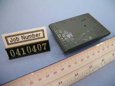
Click to zoom
Application Details
- Equipment Class
- DSC - Part 15 Security/Remote Control Transmitter
- Date of Grant
- Aug 18, 2004
- Application Purpose
- Original Equipment
- Date of Application
- Aug 18, 2004
- Equipment Note
- 433MHz RF Transmitter
- Frequency Range
- 433.92000000 - 433.92000000
- Company
- Electronics Tomorrow Ltd.
- Country
- Hong Kong
Documents & Files
Document Text
Text extracted from the exhibit documents filed with the FCC. Open a document above to read the original.
Users Manual
INSTRUCTION MANUAL Locations of Control Main Unit (Receiver) HR/RE-SYNC BUTTON MINUTE/CLEAR BUTTON YEAR/ MAX/MIN BUTTON MONTH/ 12/24 BUTTON DATE/ ∞C/∞F BUTTON SNOOZE/ALARM ON/OFF SWITCH RESET BUTTON LOCK/ALARM/TIME/CAL SWITCH SNOOZE/LIGHT BUTTON A B C D E F G H I Model 724A Feature • Calendar with day of the week display from January 1, 2003 to December 31, 2069 • Hour and minute display • 12 or 24-hour format • Indoor temperature and remote temperature • Centigrade or Fahrenheit readout • Clock operating temperature from 0∞C to 50∞C ( 32∞F to 122∞F ) • Indoor, Outdoor Temperature measuring range from -50∞C to 70∞C (-58∞F to 158∞F )* • Temperature resolution 0.1∞C * If using the wireless transmitter with temperature below 32∞F or above 122∞F, user are recommended to use Lithium battery to enhance batteries life. Before You Begin To ensure proper functioning of the RF Thermo Clock, please follow this set up procedure. • Insert batteries for main unit ( Refer to instructions for battery installation ). • Place the main unit as close as possible next to the remote unit and insert batteries for the remote unit. • Position the remote unit and main unit within effective transmission range, which in usual circumstances is 20 to 30 meters. Note that the effective range is affected by the building materials and where the main and remote unit are positioned. Try various setup for the best results. Batteries Installation Batteries installation of the main unit • Insert 2 "AA" batteries in polarity (+) and (-) as indicated • Close the battery cover • The low battery icon will show in the clock window when your batteries need replacing Batteries installation of remote unit • Insert 2 "AA" size batteries in proper polarity (+) and (-) as indicated • Close the battery door Warning : Do not mix old and new batteries Do not mix alkaline, standard (carbon-zinc), or rechargeable (nickel cadmium) batteries. Size: 140mm(W) x 177mm(H) total 8 pages (M059) #9306P.2M059P.1 • The configuration of your clock may differ somewhat from that shown in the illustration. • "AA" or "AAA" size battery. This clock may use more than one piece of battery. Please refer to the engraved battery marks inside the battery compartment for the correct battery type. A Model 7452 Remote Unit (Transmitter) SNOOZE/LIGHT H B C DE G F I M059M059 Do not touch any other buttons or settings on your clock. It will automatically receive the remote temperature. Getting Started Upon power up of the remote unit ( or pressing the reset button ), the temperature RF signal is immediately sent to the main unit. The main unit attempts to receive the RF temperature signal for 5 minutes. The main unit refreshes the RF temperature every 3 minutes. Check IN / REMOTE Temperature The indoor temperature is displayed on the IN temperature field and the remote temperature will be displayed on the REMOTE temperature field. If the RF temperature signal is not received within 5 minutes after power up of the main unit (or pressing the reset button), blank "---" will appear in the outdoor temperature window of the main unit. In this case, press the HR/SYNC button of the main unit. The main unit will attempt outdoor temperature reception for another 6 minutes. After the remote temperature shows in the lower LCD panel, place the remote unit outside in a shaded, dry area to protect it as if under an umbrella. Try relocating the unit if the main unit does not display the remote temperature after 6 minutes. Maximum and Minimum IN / REMOTE Temperature The maximum and minimum recorded temperature readings will automatically be stored in the memory. Press the Max/Min button once to display the indoor maximum and minimum record. Press the button again to show the REMOTE maximum and minimum record. The respective indicators, IN and REMOTE will be displayed. To clear the memory, press CLEAR when the maximum and minimum temperature records are shown, it will clear the record of the shown temperature field. Clock Set 1. Slide the LOCK/ALM/TIME/CAL switch to TIME position. The clock time blinks. 2. To set the time, press the HR/SYNC and MIN/CLEAR buttons until the desired time appear on the display. 3. Slide the switch to LOCK position. Alarm Set 1. Slide the LOCK/ALM/TIME/CAL switch to ALM position. The alarm time blinks. 2. To set the alarm time, press the HR/SYNC and MIN/CLEAR buttons until the desired alarm time appear on the display. 3. Slide the switch to LOCK position. Calendar Set 1. Slide the LOCK/ALM/TIME/CAL switch to CAL position. The calendar date blinks. 2. To set the calendar date, press the MONTH 12/24, DATE/∞C/∞F and YEAR/MAX/MIN button until the desired calendar date appear on the display. 3. Slide the switch to LOCK position. To Activate Alarm Function 1. Slide the SNZ/ALARM ON/OFF switch to ON position, the sign will appear on the time display. The alarm function is activated. 2. When the alarm sounds, press the Snooze/Light button. The alarm will sound the same time of the next day. 3. To deactivate the alarm function, slide the SNZ/ALARM ON/OFF switch to OFF position. To Activate the snooze alarm 1. Slide the SNZ/ALARM ON/OFF switch to SNZ position. The sign and Zz will appear on the time display. 2. When the alarm sounds, press the Snooze/Light button. The alarm will sound again in approximately 5 minutes. You may repeat this function for 10 minutes. 3. To deactivate the snooze alarm, slide the SNZ/ALARM ON/OFF switch to the OFF position. 12HR/24HR International Time Display Set Press the 12HR/24HR button to choose the desired display format. "AM" or "PM" will be displayed only in 12HR format. Centigrade (∞C) or Fahrenheit (∞F) set Press the ∞C/∞F button to choose the Centigrade or Fahrenheit readout. Note that the remote temperature display on the main unit is dominated by the selection on the main unit. Whatever the display unit of the remote unit is, it will be automatically converted to the chosen one of the main unit. P.4P.3 Trouble-Shooting • Press t…
Text truncated - open the document above for the full version.
Block Diagram
Block Diagram of 7452/3 ( Tx ) Power Control System Frequency (iii) System Frequency System Frequency 433.92MHz L.O. : 433.92 (ii) 32.768kHz (i) Raw Data Low Pass Filter MCU IC: TM8712 LCD (7452 only) Temperature sensor RF Circuit IC : U2745 Key Matrix (i) The 32.768kHz is the MCU clock frequency for normal operation. (ii) The 13.56MHz is the frequency reference of the RF circuit since it use PLL to generate 433.92MHz (iii) The 433.92MHz is the output of the RF circuit
External Photos
INTERTEK TESTING SERVICES FCC ID: PEQ745290403 External Photo (Model No.: 7452) Front View Rear View INTERTEK TESTING SERVICES FCC ID: PEQ745290403 External Photo (Model No.: 7453) Front View Rear View
ID Label/Location Info
Page 1 of 1 6/9/2004file://C:\Documents%20and%20Settings\cho\Local%20Settings\Temp\7452%20FCC%20.j
Internal Photos
INTERTEK TESTING SERVICES FCC ID: PEQ745290403 Internal Photo (Model No.: 7453) Photo-1 Photo-2 INTERTEK TESTING SERVICES FCC ID: PEQ745290403 Internal Photo (Model No.: 7453) Photo-3 Photo-4 INTERTEK TESTING SERVICES FCC ID: PEQ745290403 Internal Photo (Model No.: 7453) Photo-5 Photo-6 INTERTEK TESTING SERVICES FCC ID: PEQ745290403 Internal Photo (Model No.: 7453) Photo-7 Photo-8 INTERTEK TESTING SERVICES FCC ID: PEQ745290403 Internal Photo (Model No.: 7453) Photo-9 INTERTEK TESTING SERVICES FCC ID: PEQ745290403 Internal Photo (Model No.: 7452) Photo-1
Operational Description
Block Diagram of 7452/3 ( Tx ) Power Control System Frequency (iii) System Frequency System Frequency 433.92MHz L.O. : 432.12 (ii) 32.768kHz (i) Raw Data (i) The 32.768kHz is the MCU clock frequency for normal operation. (ii) The 13.56MHz is the frequency reference of the RF circuit since it use PLL to generate 433.92MHz (iii) The 433.92MHz is the output of the RF circuit Technical Description of the Circuit: The circuit is a RF thermometer transmitter part, the MCU TM8712 will measure the temperature and code the data. Afterward, the data is transferred to the RF circuit, it is a fully integrated IC based OOK transmitter, the IC U2745B include a VCO, PLL and a power amplifier circuit. The IC U2745B will generate the frequency by the VCO and the PLL, the frequency is controlled by the reference crystal frequency, the reference frequency is 13.56MHz, then the PLL will multiple the frequency by 32 and it will generate the 433.92MHz. When the data from the MCU TM8712 transferred to the RF IC is high, it will turn on the power amplifier inside the IC U2745B and the IC U2745B will output the 433.92MHz. If the data transferred is low, it will turn off the power amplifier and the IC U2745B will not output the RF signal. Also there is a low pass filter at the output stage of the RF IC U2745B transmitter, it will suppress the harmonic and spurious emission. Low Pass Filter MCU IC: TM8712 LCD (7452 only) Key Matrix RF Circuit IC : U2745 Te mp er atur e sensor
Test Report
• The test results reported in this test report shall refer only to the sample actually tested and shall not refer or be deemed to refer to bulk from which such a sample may be said to have been obtained. • This report shall not be reproduced except in full without prior authorization from Intertek Testing Services Hong Kong Limited. • For Terms And Conditions of the services, it can be provided upon request. • The evaluation data of the report will be kept for 3 years from the date of issuance. Intertek Testing Services Hong Kong Ltd. 2/F., Garment Centre, 576 Castle Peak Road, Kowloon, Hong Kong. Tel: (852) 2173 8888 Fax: (852) 2371 0521 Website: www.hk.intertek-etlsemko.com Electronics Tomorrow Ltd. Application For Certification (FCC ID: PEQ745290403) Transmitter 0410407 TL/ Sandy Lee August 17, 2004 INTERTEK TESTING SERVICES FCC ID: PEQ745290403 i LIST OF EXHIBITS INTRODUCTION EXHIBIT 1: General Description EXHIBIT 2: System Test Configuration EXHIBIT 3: Emission Results EXHIBIT 4: Equipment Photographs EXHIBIT 5: Product Labelling EXHIBIT 6: Technical Specifications EXHIBIT 7: Instruction Manual EXHIBIT 8: Miscellaneous Information INTERTEK TESTING SERVICES FCC ID: PEQ745290403 ii MEASUREMENT/TECHNICAL REPORT Electronics Tomorrow Ltd. MODEL: Electronics Tomorrow Ltd. 7452 (with LCD Display) Electronics Tomorrow Ltd. 7453 (without LCD Display) FCC ID: PEQ745290403 August 17, 2004 This report concerns (check one:) Original Grant X Class II Change Equipment Type: Low Power Transmitter (example: computer, printer, modem, etc.) Deferred grant requested per 47 CFR 0.457(d)(1)(ii)? Yes No X If yes, defer until: date Company Name agrees to notify the Commission by: date of the intended date of announcement of the product so that the grant can be issued on that date. Transition Rules Request per 15.37? Yes No X If no, assumed Part 15, Subpart C for intentional radiator - the new 47 CFR [12-08-03 Edition] provision. Report prepared by: Tommy Leung Intertek Testing Services 2/F., Garment Center, 576, Castle Peak Road, HONG KONG. Phone: 852-2173-8538 Fax: 852-2371-0521 INTERTEK TESTING SERVICES FCC ID: PEQ745290403 iii Table of Contents 1.0 General Description..............................................................................................2 1.1 Product Description ..............................................................................................2 1.2 Related Submittal(s) Grants .................................................................................2 1.3 Test Methodology.................................................................................................3 1.4 Test Facility ..........................................................................................................3 2.0 System Test Configuration ...................................................................................5 2.1 Justification ..........................................................................................................5 2.2 EUT Exercising Software .....................................................................................5 2.3 Special Accessories .............................................................................................5 2.4 Equipment Modification ........................................................................................6 2.5 Measurement Uncertainty ....................................................................................6 2.6 Support Equipment List and Description ..............................................................6 3.0 Emission Results ..................................................................................................8 3.1 Field Strength Calculation ....................................................................................9 3.2 Radiated Emission Configuration Photograph ....................................................11 3.3 Radiated Emission Data.....................................................................................12 4.0 Equipment Photographs .....................................................................................16 5.0 Product Labelling ................................................................................................18 6.0 Technical Specifications ....................................................................................20 7.0 Instruction Manual ..............................................................................................22 8.0 Miscellaneous Information .................................................................................24 8.1 Measured Bandwidth .........................................................................................25 8.2 Discussion of Pulse Desensitization ...................................................................26 8.3 Calculation of Average Factor ............................................................................27 8.4 Emissions Test Procedures................................................................................28 INTERTEK TESTING SERVICES FCC ID: PEQ745290403 iv List of attached file Exhibit type File Description filename Test Report Test Report report.pdf Operation Description Technical Description descri.pdf Test Setup Photo Radiated Emission radiated photos.doc Test Report Bandwidth Plot bw.pdf External Photo External Photo external photos.doc Internal Photo Internal Photo internal photos.doc Block Diagram Block Diagram block.pdf Schematics Circuit Diagram circuit.pdf ID Label/Location Label Artwork and Location label.pdf User Manual User Manual manual.pdf Test Report Timing Diagram timing.pdf INTERTEK TESTING SERVICES FCC ID: PEQ745290403 1 EXHIBIT 1 GENERAL DESCRIPTION INTERTEK TESTING SERVICES FCC ID: PEQ745290403 2 1.0 General Description 1.1 Product Description The Equipment Under Test (EUT) is a transmitter operating at 433.92MHz. The EUT is powered by 3.0V d.c. (2 x 1.5V “AA” size batteries). During the normal usage,…
Text truncated - open the document above for the full version.
Test Setup Photos
INTERTEK TESTING SERVICES FCC ID: PEQ745290403 Radiated Emissions Test Setup (Model No.: 7452) Front View Rear View INTERTEK TESTING SERVICES FCC ID: PEQ745290403 Radiated Emissions Test Setup (Model No.: 7453) Front View Rear View
Contact Information
Applicant
Steve Lam(Senior Engineering Manager)
Technical Contact
Intertek Testing Services Hong Kong Ltd.Tommy Leung
[email protected]852-2173-8538
2/F., Garment Centre, · Kowloon · Hong Kong
Non-Technical Contact
Intertek Testing Services Hong Kong Ltd.Tommy Leung
[email protected]852-2173-8538
Test Firm
Intertek Testing Services Hong KongBilly Chow
Technical Specifications
| # | Rule Parts | Frequency Range | Power Output |
|---|---|---|---|
| 1 | 15.231(e) | 433.92 MHz - 433.92 MHz | - |
Other Applications from Electronics Tomorrow Ltd.
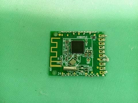
PEQA55000515
Jul 11, 2015Bluetooth Cooking Thermometer
Equipment Class
DTS - Digital Transmission System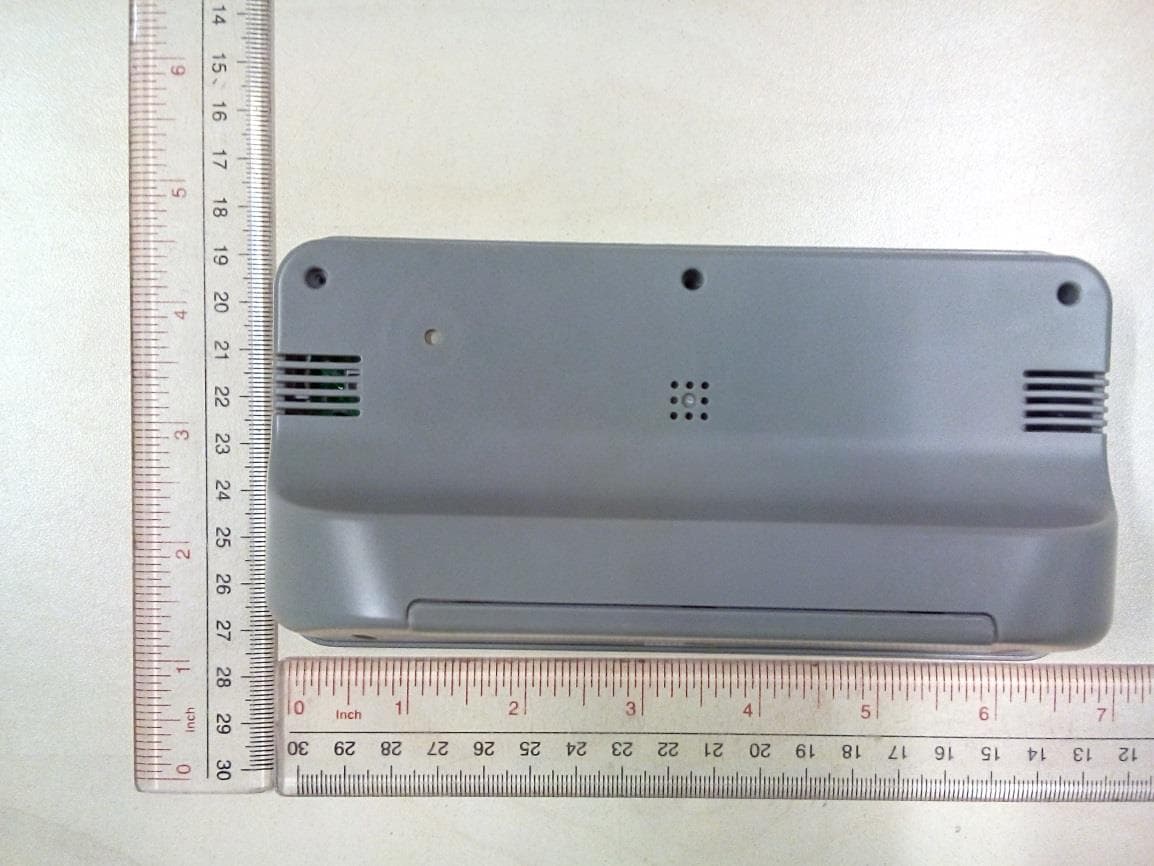
PEQ964F110813
Sep 16, 2014BLE Alarm Clock
Equipment Class
DTS - Digital Transmission System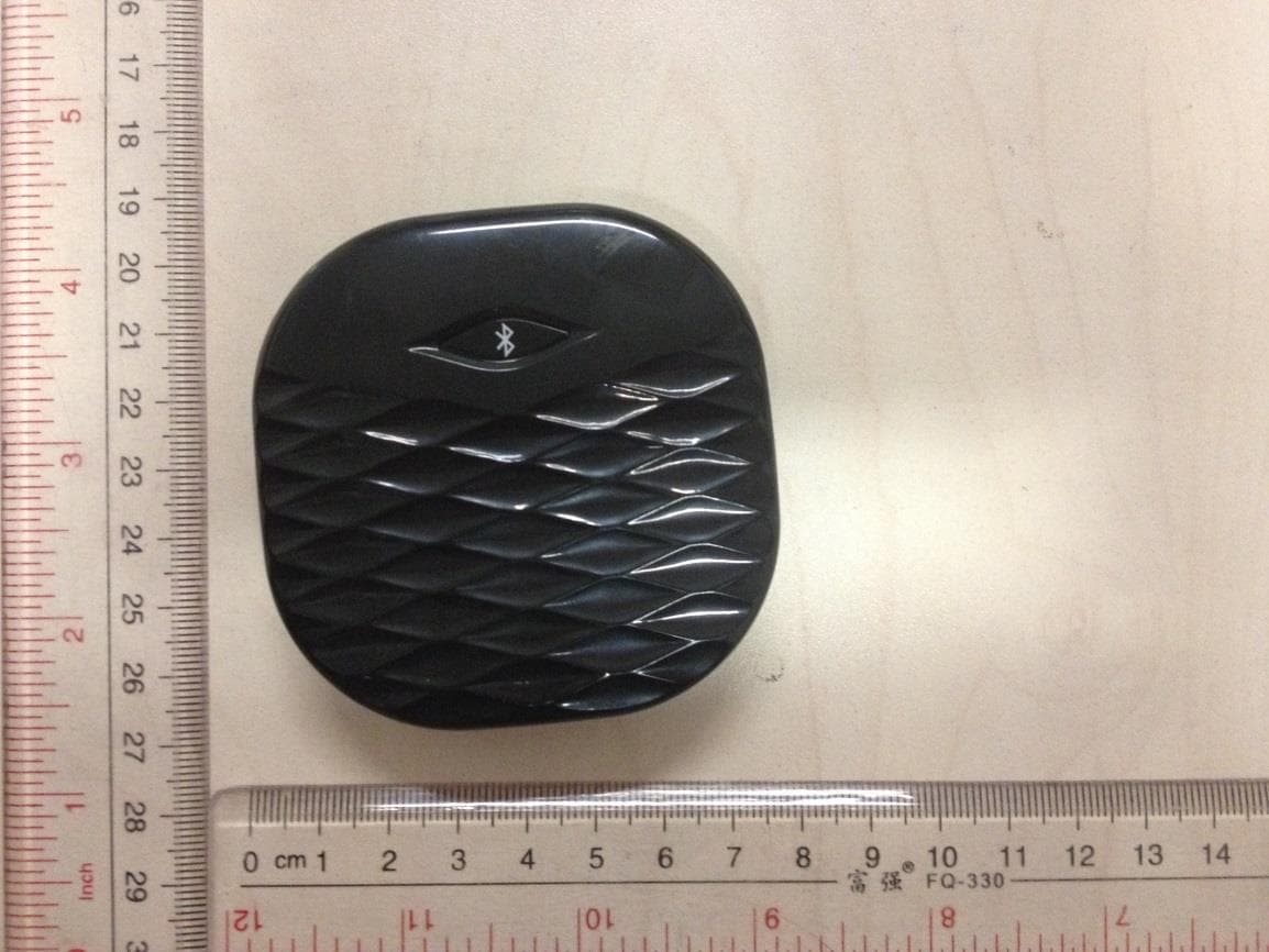
PEQA480110813
Sep 15, 2014BLE Vibration Alarm
Equipment Class
DTS - Digital Transmission System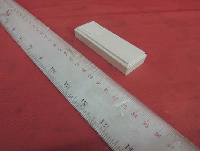
PEQA43071013
Oct 22, 2013Remote Thermo-Hygrometer
Equipment Class
DXX - Part 15 Low Power Communication Device Transmitter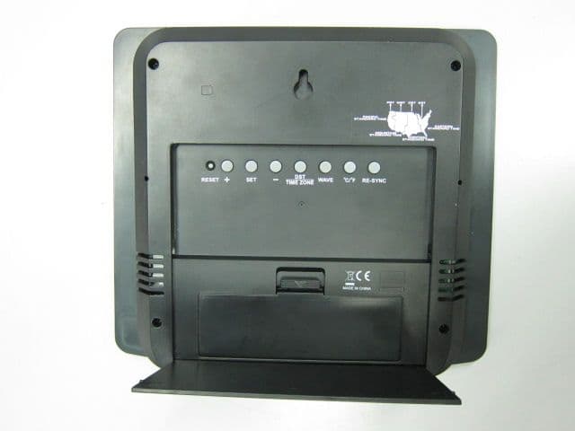
PEQ790E90712
Sep 02, 2012WWVB RC and RF wall clock
Equipment Class
CYY - Communications Receiver used w/Pt 15 Transmitter