PEQ753090303433MHz RF Thermo & Hygro Transmitter
Electronics Tomorrow Ltd.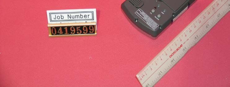
Click to zoom
Application Details
- Equipment Class
- DSC - Part 15 Security/Remote Control Transmitter
- Date of Grant
- Feb 03, 2005
- Application Purpose
- Original Equipment
- Date of Application
- Feb 03, 2005
- Equipment Note
- 433MHz RF Thermo & Hygro Transmitter
- Frequency Range
- 433.92000000 - 433.92000000
- Company
- Electronics Tomorrow Ltd.
- Country
- Hong Kong
Documents & Files
Document Text
Text extracted from the exhibit documents filed with the FCC. Open a document above to read the original.
Users Manual
INSTRUCTION MANUAL Locations of Control Main Unit (Receiver) SNOOZE/LIGHT BUTTON SNOOZE/ALARM ON/OFF SWITCH TEMP MAX/MIN BUTTON SET BUTTON + BUTTON RE-SYNC BUTTON SELECT BUTTON HUMIDITY MAX/MIN BUTTON CLEAR BUTTON - BUTTON WAVE BUTTON ûC/ûF BUTTON RESET BUTTON DST/TIME ZONE A B C D E F G H I J K L M N Model 8400 The Radio-Controlled Clock with Thermometer With the Radio-Controlled Clock, you have the most accurate timepiece within the continent. It can receive the time signal transmitted by the National Institute of Standards and Technology (NIST), which is regulated by 3 atomic clocks and deviates less than 1 second within 3,000 years. The NIST broadcasts the time signal (WWVB, 60kHz) continuously from Fort Collins, Colorado. This signal can be received anywhere in the continental USA that long wave (AM) radio reception is possible with a portable radio. It is expected that the signal can cover a distance of over 2,000 miles from the transmitter. Therefore, your clock will receive the signal within the broadcast range anywhere an AM signal can be received; generally the signal cannot be picked up in massive metal and concrete structures unless near a window. In addition, some environmental effects (see next page) may affect the transmitting distance. For more information, please study the WWVB WEB page of NIST at: http://www.boulder.nist.gov/timefreq/ Feature ¥ Receive 60kHz WWVB signal transmitted by NIST in Fort Collins,Colorado. ¥ Automatic time adjustment after signal reception. ¥ Calendar with day of the week display from January 1, 2003 to December 31, 2039 ¥ Hour, minute and second display ¥ 12 or 24-hour format ¥ Indoor temperature and remote temperature ¥ Indoor humidity and remote humidity ¥ Centigrade or Fahrenheit readout ¥ Clock operating temperature from 0ûC to 50ûC ( 32ûF to 122ûF ) ¥ Indoor, Outdoor Temperature measuring range from -50ûC to 70ûC (-58ûF to 158ûF )* ¥ Temperature resolution 0.1ûC ¥ humidity resolution 1% ¥ Time accuracy (Atomic clock): better then 1 second in 3000 years. ¥ Time accuracy (free run): average with in ±60 seconds per month * If using the wireless transmitter with temperature below 32ûF or above 122ûF, user are recommended to use Lithium battery to enhance batteries life. Attention The Radio-Controlled Clock obtains the accurate time with wireless technology. Same as all wireless devices, the receiving ability may be affected by, but not limited to, the following conditions: ¥ Long transmitting distance. ¥ Nearby mountains and valleys. ¥ Among tall buildings. ¥ Near railway, high voltage cable, etc. ¥ Near freeway, airport, etc. ¥ Near construction site. ¥ Inside concrete buildings. ¥ Near electrical appliances. ¥ Bad weather. ¥ Inside moving vehicles. ¥ Nearby metallic structures. Location Precautions This clock receives a radio wave much like a TV or radio. Be sure to locate it near a window or some other locations where reception is good. Avoid the following locations, which can interfere with proper reception. Size: 140mm(W) x 177mm(H) total 8 pages (M0xx) #xxxxP.2M0xxP.1 ¥ The configuration of your clock may differ somewhat from that shown in the illustration. ¥ "AA" or "AAA" size battery. This clock may use more than one piece of battery. Please refer to the engraved battery marks inside the battery compartment for the correct battery type. Model 7530 SELECTION RESET Button ûC/ûF A B C Remote Unit (Transmitter) FCC ID : PEQ753090303 This device complies with Part 15 of the FCC Rules.Operation is subject to the following two conditions: (1) this device may not ca- use harmful interference,and (2) this device must accept any inte rference received,including interference that may cause undesired operation. - RESET SELECTIONC/ F A B C M0xxM0xx Before You Begin To ensure proper functioning of the Weather Forecast Station, please follow this set up procedure. ¥ Insert batteries for main unit ( Refer to instructions for battery installation ). ¥ Place the main unit as close as possible next to the remote unit and insert batteries for the remote unit. ¥ Position the remote unit and main unit within effective transmission range, which in usual circumstances is 20 to 30 meters. Note that the effective range is affected by the building materials and where the main and remote unit are positioned. Try various setup for the best results. Batteries Installation Batteries installation of the main unit ¥ Insert 4 "AAA" batteries in polarity (+) and (-) as indicated ¥ Close the battery cover ¥ The low battery icon will show in the display when your batteries need replacing Batteries installation of remote unit ¥ Insert 2 "AA" size batteries in proper polarity (+) and (-) as indicated ¥ Close the battery door Warning : Do not mix old and new batteries Do not mix alkaline, standard (carbon-zinc), or rechargeable (nickel cadmium) batteries. Do not touch any other buttons or settings on your weather forcast station. It will automatically receive the outdoor temperature humidity. Getting Started ¥ Upon power up of the remote unit ( or pressing the reset button ), the temperature/humidity RF signal is immediately sent to the main unit. The main clock attempts to receive the RF temperature/humidity signal for 5 minutes. When the RF temperature/humidity signal received after power up of main unit, display will change to show the OUTDOOR readout and the main unit refreshes the RF temperature/humidity every 3 minutes. ¥ After the outdoor temperature/humidity shows in the lower LCD panel, place the remote unit outside in a shaded, dry area to protect it as if under an umbrella. ¥ If the RF temperature/humidity signal is not received within 5 minutes after power up of the main unit (or pressing the reset button), only INDOOR readout will be available and LCD keep showing INDOOR readout. In this case, press the RE-SYNC button of the main unit. The main unit will attempt outdoor temperature/humidity reception for another 6 minutes. Check INDOOR/OUTDOOR Temperature and H…
Text truncated - open the document above for the full version.
Block Diagram
Block Diagram of 7530 ( Tx ) Power Control System Frequency (iii) System Frequency System Frequency 433.92MHz 13.56MHz (ii) 32.768kHz (i) 433.92MHz (ii) Raw Data Low Pass Filter MCU IC: TM8712 LCD Thermo & Hygro sensor RF Circuit IC : U2745 Key Matrix (i) The 32.768kHz is the MCU clock frequency for normal operation. (ii) The 13.56MHz is the frequency reference of the RF circuit since it use PLL to generate 433.92MHz (iii) The 433.92MHz is the output of the RF circuit
External Photos
INTERTEK TESTING SERVICES FCC ID: PEQ753090303 External Photo Front View Rear View
Internal Photos
INTERTEK TESTING SERVICES FCC ID: PEQ753090303 Internal Photo Photo-1 Photo-2 INTERTEK TESTING SERVICES FCC ID: PEQ753090303 Internal Photo Photo-3 Photo-4 INTERTEK TESTING SERVICES FCC ID: PEQ753090303 Internal Photo Photo-5 Photo-6 INTERTEK TESTING SERVICES FCC ID: PEQ753090303 Internal Photo Photo-7 Photo-8 INTERTEK TESTING SERVICES FCC ID: PEQ753090303 Internal Photo Photo-9
Operational Description
Technical Description of the Circuit: The circuit is a RF thermometer transmitter part, the MCU TM8712 will measure the temperature and humidity and encode the data. Afterward, the data is transferred to the RF circuit, it is a fully integrated IC based OOK transmitter, the IC U2745B include a VCO, PLL and a power amplifier circuit. The IC U2745B will generate the frequency by the VCO and the PLL, the frequency is controlled by the reference crystal frequency, the reference frequency is 13.56MHz, then the PLL will multiple the frequency by 32 and it will generate the 433.92MHz. When the data from the MCU TM8712 transferred to the RF IC is high, it will turn on the power amplifier inside the IC U2745B and the IC U2745B will output the 433.92MHz. If the data transferred is low, it will turn off the power amplifier and the IC U2745B will not output the RF signal. Also there is a low pass filter at the output stage of the RF IC U2745B transmitter, it will suppress the harmonic and spurious emission.
Schematics
7530v30.sch-1 - Wed Dec 15 16:19:37 2004 75301V10.sch-1 - Thu Dec 16 10:38:49 2004
Test Report
• The test results reported in this test report shall refer only to the sample actually tested and shall not refer or be deemed to refer to bulk from which such a sample may be said to have been obtained. • This report shall not be reproduced except in full without prior authorization from Intertek Testing Services Hong Kong Limited. • For Terms And Conditions of the services, it can be provided upon request. • The evaluation data of the report will be kept for 3 years from the date of issuance. Intertek Testing Services Hong Kong Ltd. 2/F., Garment Centre, 576 Castle Peak Road, Kowloon, Hong Kong. Tel: (852) 2173 8888 Fax: (852) 2371 0521 Website: www.hk.intertek-etlsemko.com Electronics Tomorrow Ltd. Application For Certification (FCC ID: PEQ753090303) Transmitter 04195992 DL/ Sandy Lee January 17, 2005 INTERTEK TESTING SERVICES FCC ID: PEQ753090303 i LIST OF EXHIBITS INTRODUCTION EXHIBIT 1: General Description EXHIBIT 2: System Test Configuration EXHIBIT 3: Emission Results EXHIBIT 4: Equipment Photographs EXHIBIT 5: Product Labelling EXHIBIT 6: Technical Specifications EXHIBIT 7: Instruction Manual EXHIBIT 8: Miscellaneous Information INTERTEK TESTING SERVICES FCC ID: PEQ753090303 ii MEASUREMENT/TECHNICAL REPORT Electronics Tomorrow Ltd. - MODEL: 7530 FCC ID: PEQ753090303 January 17, 2005 This report concerns (check one:) Original Grant X Class II Change Equipment Type: Low Power Transmitter (example: computer, printer, modem, etc.) Deferred grant requested per 47 CFR 0.457(d)(1)(ii)? Yes No X If yes, defer until: date Company Name agrees to notify the Commission by: date of the intended date of announcement of the product so that the grant can be issued on that date. Transition Rules Request per 15.37? Yes No X If no, assumed Part 15, Subpart C for intentional radiator - the new 47 CFR [12-08-03 Edition] provision. Report prepared by: Derek Leung Intertek Testing Services 2/F., Garment Center, 576, Castle Peak Road, Kowloon, Hong Kong. Phone: 852-2173-8539 Fax: 852-2371-0521 INTERTEK TESTING SERVICES FCC ID: PEQ753090303 iii Table of Contents 1.0 General Description..............................................................................................2 1.1 Product Description ..............................................................................................2 1.2 Related Submittal(s) Grants .................................................................................2 1.3 Test Methodology.................................................................................................3 1.4 Test Facility ..........................................................................................................3 2.0 System Test Configuration ...................................................................................5 2.1 Justification ..........................................................................................................5 2.2 EUT Exercising Software .....................................................................................5 2.3 Special Accessories .............................................................................................5 2.4 Equipment Modification ........................................................................................6 2.5 Measurement Uncertainty ....................................................................................6 2.6 Support Equipment List and Description ..............................................................6 3.0 Emission Results ..................................................................................................8 3.1 Field Strength Calculation ....................................................................................9 3.2 Radiated Emission Configuration Photograph ....................................................11 3.3 Radiated Emission Data.....................................................................................12 4.0 Equipment Photographs .....................................................................................15 5.0 Product Labelling ................................................................................................17 6.0 Technical Specifications ....................................................................................19 7.0 Instruction Manual ..............................................................................................21 8.0 Miscellaneous Information .................................................................................23 8.1 Measured Bandwidth .........................................................................................24 8.2 Discussion of Pulse Desensitization ...................................................................25 8.3 Calculation of Average Factor ............................................................................26 8.4 Emissions Test Procedures................................................................................27 INTERTEK TESTING SERVICES FCC ID: PEQ753090303 iv List of attached file Exhibit type File Description filename Test Report Test Report report.pdf Operation Description Technical Description descri.pdf Test Setup Photo Radiated Emission radiated photos.doc Test Report Bandwidth Plot bw.pdf External Photo External Photo external photos.doc Internal Photo Internal Photo internal photos.doc Block Diagram Block Diagram block.pdf Schematics Circuit Diagram circuit.pdf ID Label/Location Label Artwork and Location label.pdf User Manual User Manual manual.pdf Test Report Timing Diagram timing.pdf INTERTEK TESTING SERVICES FCC ID: PEQ753090303 1 EXHIBIT 1 GENERAL DESCRIPTION INTERTEK TESTING SERVICES FCC ID: PEQ753090303 2 1.0 General Description 1.1 Product Description The Equipment Under Test (EUT) is a Transmitter operating at 433.92MHz. The EUT is powered by 3.0VDC (2 x “AA” size batteries). During normal use, it measures the temperature value and transmits it to the corresponding receiver. The temperature…
Text truncated - open the document above for the full version.
Test Report
Details of Data Frame Format: 11bits-syn bits: 00000000000 b 1bit-start bit: 1 b 3bits-Channel ID: Channel ID: • Channel 1 (001 b ) • Channel 2 (000 b ) • Channel 3 (010 b ) 11bits-temperature(Hex): • Temperature range: –50 0 C ~ +70 0 C • Oven +70 0 C: 700 H • Below -50 0 C: 600 H • –50 0 C ~ +70 0 C: Hex (temperature d + 500 d ) e.g. 25.5 0 C => Hex(255 d +500 d )=>2F3 H 7bits-humidity(Hex): • Humidity range: 0%~100% • Direct converts Dec to Hex value 3bits- miscellanies (low battery): Bit 3 is low battery status, if this bit is 1, it indicate low battery now. If this bit is 0, it indicates enough battery now. • Battery Enough: 000 • Battery Low: 100 4bits-CRC check code: It is generated by P (x)=11001 b and data (3bits - Channel ID, 11bits – temperature (Hex), 7bits - humidity (Hex), 3bits – miscellanies) Total number of bit is 40 Logic "0"Logic "1" 6 ms2 ms2 ms6 ms
Test Setup Photos
INTERTEK TESTING SERVICES FCC ID: PEQ753090303 Radiated Emissions Test Setup Front View Rear View
Contact Information
Applicant
Steve Lam(Senior Engineering Manager)
Technical Contact
Intertek Testing Services Hong Kong Ltd.Derek Leung
[email protected]852-2173-8539
2/F., Garment Centre · Kowloon · Hong Kong
Non-Technical Contact
Intertek Testing Services Hong Kong Ltd.Derek Leung
[email protected]852-2173-8539
Test Firm
Intertek Testing Services Hong KongBilly Chow
Technical Specifications
| # | Rule Parts | Frequency Range | Power Output |
|---|---|---|---|
| 1 | 15.231(e) | 433.92 MHz - 433.92 MHz | - |
Other Applications from Electronics Tomorrow Ltd.
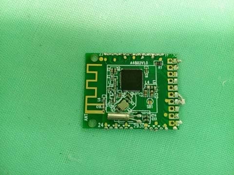
PEQA55000515
Jul 11, 2015Bluetooth Cooking Thermometer
Equipment Class
DTS - Digital Transmission System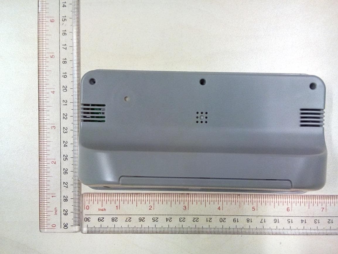
PEQ964F110813
Sep 16, 2014BLE Alarm Clock
Equipment Class
DTS - Digital Transmission System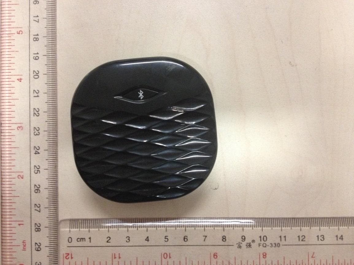
PEQA480110813
Sep 15, 2014BLE Vibration Alarm
Equipment Class
DTS - Digital Transmission System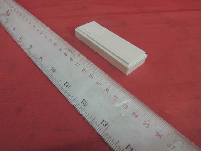
PEQA43071013
Oct 22, 2013Remote Thermo-Hygrometer
Equipment Class
DXX - Part 15 Low Power Communication Device Transmitter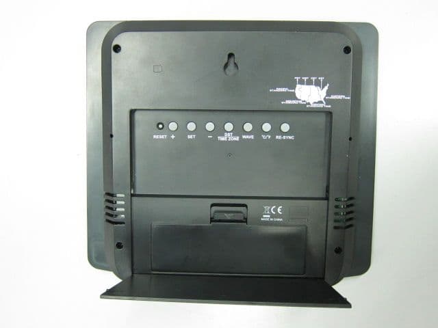
PEQ790E90712
Sep 02, 2012WWVB RC and RF wall clock
Equipment Class
CYY - Communications Receiver used w/Pt 15 Transmitter