PML433A04Receiver
Nice S.p.A.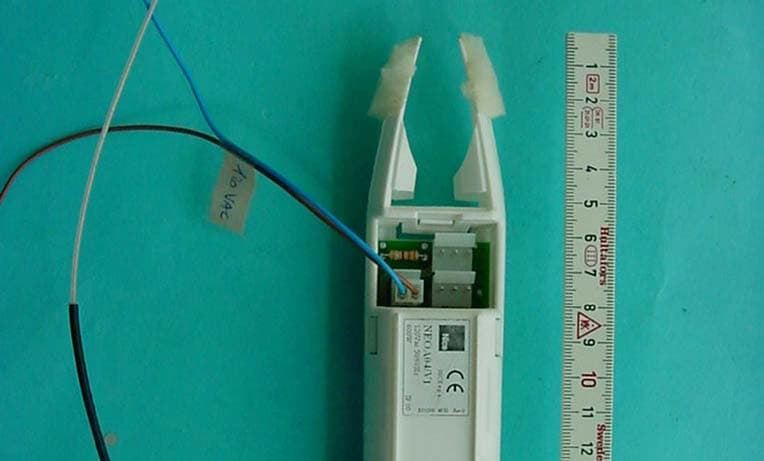
Click to zoom
Application Details
- Equipment Class
- CYY - Communications Receiver used w/Pt 15 Transmitter
- Date of Grant
- Sep 01, 2004
- Application Purpose
- Original Equipment
- Date of Application
- Sep 01, 2004
- Equipment Note
- Receiver
- Frequency Range
- 433.92000000 - 433.92000000
- Company
- Nice S.p.A.
- Country
- Italy
Documents & Files
Document Text
Text extracted from the exhibit documents filed with the FCC. Open a document above to read the original.
Users Manual
This device complies with Part 15 of the FCC Rules. Operation is subject to the following two conditions: (1) this device my not cause harmful interference, and (2) this device must accept any interference received, including interference that may cause undesired operation. Warning: Changes or modifications made to this equipment not expressly approved by NICE S.p.A. may void the FCC authorization to operate this equipment. This equipment has been tested and found to comply with the limits for a Class B digital device, pursuant to Part 15 of the FCC Rules. These limits are designed to provide reasonable protection against harmful interference in a residential installation. This equipment generates, uses and can radiate radio frequency energy and, if not installed and used in accordance with the instructions, may cause harmful interference to radio communications. However, there is no guarantee that interference will not occur in a particular installation. If this equipment does cause harmful interference to radio or television reception, which can be determined by turning the equipment off and on, the user is encouraged to try to correct the interference by one or more of the following measures: • Reorient or relocate the receiving antenna. • Increase the separation between the equipment and receiver. • Connect the equipment into an outlet on a circuit different from that to which the receiver is connected. • Consult the dealer or an experienced radio/TV technician for help. IST173 4 8 51 rev.0 00
Users Manual
neomat tubular motor Instrukcje i uwagi dla instalatora Istruzioni ed avvertenze per l’installatore Instructions and warnings for the fitter Instructions et recommandations pour l’installateur Anweisungen und Hinweise für den Installateur Instrucciones y advertencias para el instalador 2 Warnings: The “NEOMAT” series motors have been designed for the automation of awnings; any other use is considered improper and is prohibited. These motors are intended for residential use. Maximum continuous oper- ating time is 4 minutes with a 20% cycle. When selecting the type of motor based on the application, you should consider the nominal torque and the operating time shown on the rating plate. The minimum diameter of the tube in which the motor can be installed is 40 mm for NEOMAT ST, 52 mm for NEOMAT MT and 70 mm for NEOMAT LT. The motor must be installed by qualified personnel in compliance with current safety regulations. Minimum installation height is 2.5 m from the ground or floor. Easy access must in any case be ensured. The horizontal clearance between the fully open awning and any stationary object must be at least 0.4 m. In the case of units for outdoor use the PVC power cable must be installed inside a protection duct. The tubular motor must not be subjected to crushing, impacts, falls or contact with any kind of liquid. Do not perforate or drive screws into any part of the tubular motor (fig. 1). For maintenance and repairs contact a qualified technician (fig. 1). The NEOMAT ST Ø35mm, NEOMAT MT Ø45mm (fig.2) and NEO- MAT LTØ58mm tubular motors feature an electronic control unit with incorporated radio receiver, operating at a frequency of 433.92 MHz, with rolling code technology, to guarantee high levels of security. Up to 14 “ERGO” and “PLANO” series radio controls (fig.3) or radio-sen- sors can be memorised for each motor. The control unit incorporated in the motor is also equipped with a high precision electronic limit switch system capable of continuous- ly monitoring the position of the awning. The range of movement, i.e. the closed/open positions (plus any intermediate positions) can be programmed and memorised; after each command, the movement stops automatically when these positions are reached. The electronic limit switch can compensate for any stretching of the fabric (“CAT” function), guaranteeing the perfect closure of the shut- ter box and preventing any slack in the fabric when the awning is open. The NEOMAT motors can be programmed for “RDC” torque reduction, a function that decreases motor torque by approximately 50% just before the awning closes completely to prevent excessive stretching of the fabric. NEOMAT also features an “RDT” draw release function that reduces the stretch of the fabric momentarily after the closing operation has been completed, to prevent pro- longed stretching. The CAT, RDC and RDT functions have been especially studied to simulate the careful and meticulous behaviour of a person who opens and closes the awning manually. The range of movement and a few additional functions can be pro- grammed through the radio controls. A beep will sound to guide the various phases. The motors can also be controlled through an exter- nal button (with step-by-step function) or a Bus (“TTBUS”). Optional wind, sun and rain sensors activate the system automati- cally whenever the weather conditions demand it. 1) Product description 2) Installation Proceed as follows to prepare the motor (fig. 5): 1. Position the idle ring nut (E) on the motor (A) until it fits into the corresponding idle ring (F). 2. Mount the draw ring nut (D) on the motor shaft. On NEOMAT ST the ring nut snaps on automatically. 3. On NEOMAT MT, fasten the draw ring nut with the snap ring. Figure 4 A:NEOMAT tubular motor B:Fastening clips or split pins C:Support and spacer D:Draw ring nut E:Idle ring nut F:Idle ring NEOMAT is produced by Motus S.p.a. (TV) I. ERGO, PLANO, VOLO are produced by Nice S.p.a. (TV) I. Motus S.p.a. is an affiliate of the Nice S.p.a. group Fit the assembled motor into the awning’s winding tube until it touches the end of the idle ring nut (E). Fasten the tube to the draw ring nut (D) using the M4x10 screw in order to prevent the motor from slipping or sliding axially (fig. 6). Finally, secure the motor head to the special support (C) with the spacer (if any), using the clips or split pin (B). 2.1) Electrical connections WARNING: For motor connections, an omnipolar discon- necting device with a 3-mm minimum distance between contacts must be provided for disconnection from the mains power supply (disconnecting switch or plug and socket, etc.). WARNING: carefully follow all the connection instructions. If you have any doubts do not make experiments but con- sult the relevant technical specifications sheets which are also available on the web site "www.niceforyou.com". An incorrect connection may be dangerous and cause damage to the system. The cable used for the electrical connections of the NEOMAT MT motor has 6 wires: •Supply line from the power mains: Phase, Neutral and Earth. •Extra low voltage control signals (SELV): Step-by-step or “TTBUS” Bus and weather sensors. ! ! Brown= Phase Blue= Neutral Yellow/Green = Earth Black= Common (0V) White= Step-by-Step + “TTBUS” Orange = Weather sensors Yellow label Green label GB 3 2.2) Connector and power supply cable (this section refers only to the NEOMAT MT version and concerns customer service personnel only). WARNING: if the power cord is damaged it must be replaced with an identical type supplied by the manufacturer or an authorised customer service centre. If it is necessary to disconnect the motor from the power supply cable proceed as shown in the figures below: ! The NEOMAT series tubular motors are equipped with an electronic limit switch system. The electronic control unit interrupts the move- ment when the awning reaches the programmed open or closed positions. These positions must be programmed into the memory after the …
Text truncated - open the document above for the full version.
Cover Letter(s)
N N i i c c e e S S p p A A V V i i a a P P e e z z z z a a A A l l t t a a , , 1 1 3 3 Z Z . . I I . . R R u u s s t t i i g g n n è è I I - - 3 3 1 1 0 0 4 4 6 6 O O d d e e r r z z o o T T V V I I t t a a l l i i a a P P h h o o n n e e + + 3 3 9 9 . . 0 0 4 4 2 2 2 2 . . 8 8 5 5 3 3 8 8 3 3 8 8 F F a a x x + + 3 3 9 9 . . 0 0 4 4 2 2 2 2 . . 8 8 5 5 3 3 5 5 8 8 5 5 P P . . I I V V A A 0 0 3 3 0 0 9 9 9 9 3 3 6 6 0 0 2 2 6 6 9 9 i i n n f f o o @ @ n n i i c c e e f f o o r r y y o o u u . . c c o o m m w w w w w w . . n n i i c c e e f f o o r r y y o o u u . . c c o o m m CONFIDENTIALITY REQUEST Federal Communication Commission Equipment Authorization Division, Application Processing Branch 7435 Oakland Mills Road Columbia, MD 21048 DATE 22/03/2004 TO WHOM IT MAY CONCERN Pursuant to Paragraphs §0.457 and 0.459 of the Commission’s Rules (47 C.F.R.) and Section §552(b)(4) of the Freedom of Information Act, Company requests confidentiality for the following products: FCC ID Number Product Title/Model PML 433A04 NEOA04/V1 For the product stated above, we request that the following information be held confidential: 1. Circuit diagrams, BOM, and PCBs submitted as Equipment Authorization Electronic Filing attachment: "schematics”. 2. Block diagram submitted as Equipment Authorization Electronic Filing attachment: “blockdiagram”. 3. Operational description submitted as Equipment Authorization Electronic Filing attachment: “operational description” The above exhibits contain Company trade secrets and proprietary information that could be of benefit to our competitors regarding the design of our mobile handset. This material is not customarily available to the general public and we request that it be withheld from public inspection. If you have any questions, please feel free to contact me at the address shown below. Sincerely, Name: Oscar Marchetto Company: Nice S.p.A. Address: Via Pezza Alta, 13 Z.I. Rustignè I-31046 Oderzo (TV) Phone: +39.0422853838 Email: [email protected]
External Photos
CETECOM ICT Services GmbH Test report no.: 2-3605-01-06/04 Issue Date: 2004-04-22 Page 18 (21) Photographs of the equipment Photograph no.: 1 CETECOM ICT Services GmbH Test report no.: 2-3605-01-06/04 Issue Date: 2004-04-22 Page 19 (21) Photographs of the equipment Photograph no.: 2
ID Label/Location Info
Neo A04 labeling Redatto da: Data: Campagnaro Paolo 21/07/04 Dimensions: 47 X 38 mm (l Xh)
Internal Photos
CETECOM ICT Services GmbH Test report no.: 2-3605-01-06/04 Issue Date: 2004-04-22 Page 20 (21) Photographs of the equipment Photograph no.: 3 CETECOM ICT Services GmbH Test report no.: 2-3605-01-06/04 Issue Date: 2004-04-22 Page 21 (21) Photographs of the equipment Photograph no.: 4
Test Report
CETECOM ICT Services GmbH Radio Satellite Communication Untertürkheimer Straße 6-10 . D-66117 SaarbrückenTelefon: +49 (0)681 598-9100Telefax: -9075 RSC11Issued test report consists of 21 pagesPage 1 (21) BLUETOOTH TM is a trademark owned by Bluetooth SIG, Inc. and licensed to CETECOM Recognized by the Federal Communications Commission Anechoic chamber registration no.: 90462 (FCC) Anechoic chamber registration no.: 3463 (IC) TCB ID: DE 0001 Accredited by the German Accreditation Council DAR–Registration Number TTI–P–G 081/94-D0 Independent ETSI compliance test house ETSI Accredited Bluetooth™ Test Facility (BQTF) Test report No. : 2-3605-01-06/04 Standard : Part 15 (Receiver) Applicant : Nice SPA Type : NEO A04/V1 CETECOM – ICT Services GmbH Untertürkheimerstr. 6-10 66117 Saarbrücken, Germany Telephone: + 49 (0) 681 / 598-0 Fax: + 49 (0) 681 / 598-9075 CETECOM ICT Services GmbH Test report no.: 2-3605-01-06/04 Issue Date: 2004-04-22 Page 2 (21) Table of Contents 1 General information 1.1 Notes 1.2 Testing laboratory 1.3 Details of applicant 1.4 Application details 1.5 Test item 1.6 Test standards 2 Technical test 2.1 Summary of test results 2.2 Test report CETECOM ICT Services GmbH Test report no.: 2-3605-01-06/04 Issue Date: 2004-04-22 Page 3 (21) 1 General information 1.1 Notes The test results of this test report relate exclusively to the test item specified in 1.5. The CETECOM ICT Services GmbH does not assume responsibility for any conclusions and generalizations drawn from the test results with regard to other specimens or samples of the type of the equipment represented by the test item. The test report may only be reproduced or published in full. Reproduction or publication of extracts from the report requires the prior written approval of the CETECOM ICT Services GmbH. Test laboratory manager: 2004-04-23RSC - 8414Ames H. DateSectionNameSignature Technical responsibility for area of testing: 2004-04-23RSC - 8412Hausknecht D. DateSectionNameSignature CETECOM ICT Services GmbH Test report no.: 2-3605-01-06/04 Issue Date: 2004-04-22 Page 4 (21) 1.2 Testing laboratory CETECOM ICT Services GmbH Untertürkheimer Straße 6 - 10 66117 Saarbrücken Germany Telefone: + 49 681 598 - 9100 Telefax : + 49 681 598 - 9075 E-mail: [email protected] Internet: www.cetecom-ict.de Accredited testing laboratory The test laboratory (area of testing) is accredited according to DIN EN ISO/IEC 17025. DAR registration number: TTI-P-G-081/94-D0 Listed by: Federal Communications Commission (FCC) Identification/Registration No: 90462 Anechoic chamber registration no.: 3463 (IC) Accredited Bluetooth TM Test Facility (BQTF) BLUETOOTH TM is a trademark owned by Bluetooth SIG, Inc. and licensed to CETECOM 1.3Details of applicant Name :Nice SpA Street :Viia Pezza Alltta,, 13 Z..II.. Rusttiignè City :I-31046 Oderzo (TV) Country :Italy Telephone:+39 0422 853838 Fax :+39 0422 853585 E-mail :[email protected] Contact person: Name : Mr. Oscar Marchetto Telephone : +39 0422 853838 Telex : +39 0422 853585 E-mail : [email protected] 1.4Application details Date of receipt of test item : 2004-04-08 Date of test: 2004-04-21 Person(s) who have been : Mr. Paolo Campagnaro present during the test CETECOM ICT Services GmbH Test report no.: 2-3605-01-06/04 Issue Date: 2004-04-22 Page 5 (21) 1.5TEST ITEM Type of equipment :Remote Control Receiver Type designation: NEO A04/V1 Manufacturer :Same as applicant Street : City: Country: Serial number :- / - Additional information: Frequency:433.92 MHz Type of modulation:A1D Channel spacing:>25 kHz Number of channels :1 Antenna:Wired antenna Power supply :120 VAC Temperature range :-20°C - +60°C FCC ID : 1.6TEST STANDARDS: FCC Part 15 CETECOM ICT Services GmbH Test report no.: 2-3605-01-06/04 Issue Date: 2004-04-22 Page 6 (21) 2 Technical test The radiated measurements are performed in vertical and horizontal plane in the frequency range from 9 kHz to 20 GHz in semi-anechoic chambers. The EUT is positioned on a non-conductive support with a height of 0.80 m above a conductive ground plane that covers the whole chamber. The receiving antennas are conform with specifications ANSI C63.2-1987 clause 15 and ANSI C63.4-1992 clause 4.1.5. These antennas can be moved over the height range between 1.0 m and 4.0 m in order to search for maximum field strength emitted from EUT. The measurement distances between EUT and receiving antennas are indicated in the test setups for the various frequency ranges. For each measurement, the EUT is rotated in all three axes until the maximum field strength is received. The wanted and unwanted emissions are received by spectrum analyzers where the detector modes and resolution bandwidths over various frequency ranges are set according to requirement ANSI C63-4-1992 clause 4.2. Antennas are conform with ANSI C63.2-1996 item 15. 9 kHz - 30 MHz: Quasi Peak measurement, 9kHz Bandwidth, passive loop antenna. 30 MHz - 200 MHz: Quasi Peak measurement, 120KHz Bandwidth, biconical antenna 200MHz - 1GHz: Quasi Peak measurement, 120KHz Bandwidth, log periodic antenna 1GHz: Average, RBW 1MHz, VBW 10 Hz, wave-guide horn Remarks: No deviations from the technical specification(s) were ascertained in the course of the tests performed. FINAL VERDICT: PASS CETECOM ICT Services GmbH Test report no.: 2-3605-01-06/04 Issue Date: 2004-04-22 Page 7 (21) 2.2Test report TEST REPORT Test report no. : 2-3605-01-06/04 CETECOM ICT Services GmbH Test report no.: 2-3605-01-06/04 Issue Date: 2004-04-22 Page 8 (21) TEST REPORT REFERENCE SPOURIOUS EMISSIONS PART 15.1099 CONDUCTED EMISSIONS § 15.107/20712 TEST EQUIPMENT AND ANCILLARIES USED FOR TESTS13 TEST SITE15 PHOTOGRAPHS OF THE EQUIPMENT18 CETECOM ICT Services GmbH Test report no.: 2-3605-01-06/04 Issue Date: 2004-04-22 Page 9 (21) REFERENCE NUMBER(S) OF TEST EQUIPMENT USED (for reference numbers see test equipment listing) 52-63 SPOURIOUS EMISSIONSPART 15.109 SPURIOUS EMISSIONS LEVEL (μV/m) 433 MHz f (MHz) DetectorLevel (μV/m) f (M…
Text truncated - open the document above for the full version.
Test Setup Photos
CETECOM ICT Services GmbH Test report no.: 2-3605-01-06/04 Issue Date: 2004-04-22 Page 15 (21) Test site CETECOM ICT Services GmbH Test report no.: 2-3605-01-06/04 Issue Date: 2004-04-22 Page 16 (21) Test site CETECOM ICT Services GmbH Test report no.: 2-3605-01-06/04 Issue Date: 2004-04-22 Page 17 (21) Test site
Contact Information
Applicant
Enrico Campion(Laboratory Manager)
Test Firm
Cetecom ICT Services GmbHRalf Hoehn
Technical Specifications
| # | Rule Parts | Frequency Range | Power Output |
|---|---|---|---|
| 1 | 15B | 433.92 MHz - 433.92 MHz | - |
Other Applications from Nice S.p.A.
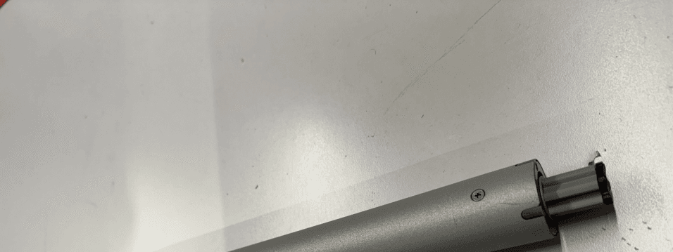
PMLILIONBD
May 26, 2026Tubular Motor
Equipment Class
DSC - Part 15 Security/Remote Control Transmitter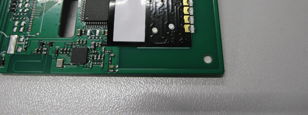
PMLDOMIP18
Sep 29, 2025Handheld TX
Equipment Class
DSR - Part 15 Remote Control/Security Device Transceiver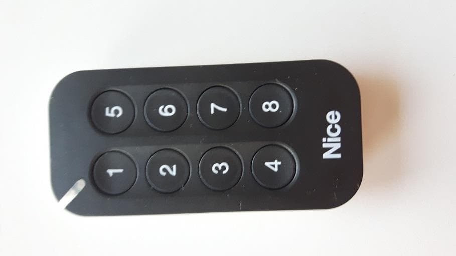
PMLMYGOA
May 03, 2022Transceiver Control
Equipment Class
DSR - Part 15 Remote Control/Security Device Transceiver
PMLOXILRA
Jun 30, 2020Transceiver control
Equipment Class
DTS - Digital Transmission System
PMLON3ELRA
Jun 30, 2020Transceiver control
Equipment Class
DTS - Digital Transmission System