PML433ONALow Power Transmitter at 433.92 MHz
Nice S.p.A.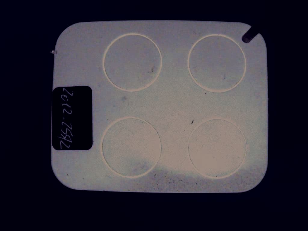
Click to zoom
Application Details
- Equipment Class
- DSC - Part 15 Security/Remote Control Transmitter
- Date of Grant
- Apr 04, 2013
- Application Purpose
- Original Equipment
- Date of Application
- Apr 03, 2013
- Equipment Note
- Low Power Transmitter at 433.92 MHz
- Frequency Range
- 433.92000000 - 433.92000000
- Company
- Nice S.p.A.
- Country
- Italy
Documents & Files
Document Text
Text extracted from the exhibit documents filed with the FCC. Open a document above to read the original.
Users Manual
PRODUCT DESCRIPTION AND INTENDED USE The transmitters in this range are designed for the control of automatic door openers, gate openers and simi- lar devices: any other use is improp- er and prohibited! For mounting the accessories, refer to Figures C-D. The “NiceOpera” system Era One and Era Inti range transmitters are part of the “NiceOpera” system. This system has been designed by Nice for the purpose of optimizing and facilitating the programming, operation and maintenance of the devices nor- mally utilized in automation systems. The system comprises several devices capable of exchanging data and infor- mation via radio, using a new coding system called “O-Code/A”, or through physical connection. THE PRODUCT’S FUNCTIONS • The transmitter adopts a transmis- sion technology called “O-Code/A”, featuring a variable code (rolling-code) which significantly im pro ves the com- mands’ transmission speed. • The transmitter incorporates a “Memory”, a “Proximity Receiver” and an “Enable Code” which, together, allow you to carry out, by ra dio control, operations and programming typical of the NiceOpera system. TESTING THE TRANSMITTER Before memorizing the transmitter in the au tomation system’s Receiver, check its proper operation by press- ing any key and observing whether the Led lights up (fig. A). If it does not, refer to the section entitled “Replacing the Battery” in this manual. MEMORIZING THE TRANS- MITTER In order to use all the new functions of the transmitter, it must be asso- ciated with the Receivers with the “O-Code/A” coding system (to iden- tify these models, refer to the Nice products catalogue). Note – the transmitter is also compat- ible with all the Receivers that use the “Flo-R/A” coding system (to identify these models, refer to the Nice prod- ucts catalogue); in this case, however, the typical functions of the NiceOpera System cannot be used. To memorize the transmitter in a Receiver, you can choose one of the following operating procedures: • Memorization in “Mode I” • Memorization in “Mode II” • Memorization through the “Certificate Number” • Memorization through the “Enable Co de” received from a previously me mo rized transmitter. The operating procedures for these memorization methods are provided in the instruction manual of the Receiver or Control Unit with which the trans- mitter is to be used. These manuals are also available on the internet site: www.niceforyou.com. In these manu- ENGLISH als, the transmitter keys are identi- fied by numbers. Therefore, to match these numbers with the corresponding transmitter keys, see fig. A. A - Memorization “Mode I” This procedure allows you to memo- rize all the transmitter keys, at once, in the receiver. The keys are automati- cally associated to each control man- aged by the Control Unit according to a factory-set sequence. B - Memorization “Mode II” This procedure enables the memo- rization of a single transmitter key in the receiver. In this case, the user will select from among the commands managed by the Control Unit (4 or 15 depending on the control unit) the one he wishes to associate to the key that is being memorized. Note – the pro- cedure must be repeated for each sin- gle key that must be memorized. C - Memorization using the “CER- TIFICATE number” [with O-Box programming unit] This procedure is designed specifi- cally for the devices belonging to the NiceOpera system, with “O-Code/A” coding system. Each Receiver in this system is associated to a designated number, called “CERTIFICATE”, that identifies and certifies it. The use of this “certificate” has the advantage of simplifying the transmitter memoriza- tion procedure in the Receiver, since the installer is no longer obliged to operate within the reception range of the Receiver. Indeed, the proce- dure allows you, with the help of the “O-Box” programming unit, to program the transmitter for memori- zation even from a remote location, away from the installation site (at the installer’s own premises, for instance - fig. E). D - Memorization using the “ENA- BLE Code” [between two transmit- ters] This procedure is designed specifi- cally for the devices belonging to the NiceOpera system, with “O-Code/A” coding system. The transmitters with this coding system have a secret code called “ENA BLE CODE”. This “Ena- ble”, once it has been transferred from an old transmitter (previously memo- rized) to a new compatible transmitter (fig. F) enables the latter to be recog- nized and automatically memorized by a Re ceiver. The transfer can also be made between transmitters of different families (eg, between Era One and Era Inti). The procedure is as foll ows: 01. Hold two transmitters together so they are touching, a “NEW” one to be memorized and an “OLD”, previously memori zed, one (fig. F). 02. Press any key on the NEW transmitter and hold it down until the Led of the OLD transmitter lights up. Then re lease the key (the Led of the OLD transmitter will start blinking). 03. Next, press any key on the OLD transmitter and hold it down until the Led of the NEW trans- mitter lights up. Then release the key (the Led will go off, indicating the end of the procedure and the successful transfer of the “Enable Code” in the NEW transmitter). Error signals via Leds 4 flashes = transfer of “Enable code” disabled. 6 flashes = transfer of “Enable code” disabled between different transmit- ters. 10 flashes = communication error between devices. 15 flashes = memorisation failed due to time limit exceeded. The first 20 times that the transmit- ter is used, it will transmit this “Enable Code” to the Re ceiver along with the command. Once it has recognized the “Enable” signal, the Re ceiver will auto- matically memorize the identity code of the transmitter that has transmitted it. REPLACING THE BATTERY When the battery runs down the range of the transmitter is significantly reduced. When pressing any key you will find that the Led takes a while to light up (= battery almost exhausted) an…
Text truncated - open the document above for the full version.
Block Diagram
NICE SPA PAG. 5 Technical Schemes All the transmitters Loop Antenna Antenna Filter SAW1 & Q3 433.92 MHz OSCILLAT. IC1 Encoder To Q1,IC1 3 VCC Battery T1,T2 buttons L5 Q1 Q2 RX
Cover Letter(s)
N N i i c c e e S S p p A A V V i i a a P P e e z z z z a a A A l l t t a a , , 1 1 3 3 Z Z . . I I . . R R u u s s t t i i g g n n è è I I - - 3 3 1 1 0 0 4 4 6 6 O O d d e e r r z z o o T T V V I I t t a a l l i i a a C C a a p p . . S S o o c c . . € € 1 1 1 1 . . 6 6 0 0 0 0 . . 0 0 0 0 0 0 i i . . v v . . P P h h o o n n e e + + 3 3 9 9 . . 0 0 4 4 2 2 2 2 . . 8 8 5 5 3 3 8 8 3 3 8 8 F F a a x x + + 3 3 9 9 . . 0 0 4 4 2 2 2 2 . . 8 8 5 5 3 3 5 5 8 8 5 5 P P . . I I V V A A 0 0 3 3 0 0 9 9 9 9 3 3 6 6 0 0 2 2 6 6 9 9 i i n n f f o o @ @ n n i i c c e e f f o o r r y y o o u u . . c c o o m m w w w w w w . . n n i i c c e e f f o o r r y y o o u u . . c c o o m m 022311 – 6 Authority to Act as Agent Date: 2012-12-14 American Certification Body, Inc. 6731 Whittier Avenue Suite C110 McLean, VA 22101 To Whom It May Concern: _______IMQ S.p.A is authorized to act on our behalf, until otherwise notified, for applications to American Certification Body, Inc. (ACB). We certify that we are not subject to denial of federal benefits, that includes FCC benefits, pursuant to Section 5301 of the Anti-Drug Abuse Act of 1988, 21 U.S.C. 862. Further, no party, as defined in 47 CFR 1.2002 (b), to the application is subject to denial of federal benefits, that includes FCC benefits. Thank you, Agency Agreement Expiration Date: _____12 months (Typically 8 – 12 months)_____ By: ___________ __ Mr. Oscar Marchetto ____________ (Signature 1 ) (Print name) Title: __ Electronic Direct______________ On behalf of: __ Nice S.p.A._____________ (Company Name) Telephone: _ +39 0422 853838 ____ 1 - Must be signed by applicant contact given for applicant on the FCC site, or by the authorized agent if an appropriate authorized agent letter has been provided. Letters should be placed on appropriate letterhead. N N i i c c e e S S p p A A V V i i a a P P e e z z z z a a A A l l t t a a , , 1 1 3 3 Z Z . . I I . . R R u u s s t t i i g g n n è è I I - - 3 3 1 1 0 0 4 4 6 6 O O d d e e r r z z o o T T V V I I t t a a l l i i a a C C a a p p . . S S o o c c . . € € 1 1 1 1 . . 6 6 0 0 0 0 . . 0 0 0 0 0 0 i i . . v v . . P P h h o o n n e e + + 3 3 9 9 . . 0 0 4 4 2 2 2 2 . . 8 8 5 5 3 3 8 8 3 3 8 8 F F a a x x + + 3 3 9 9 . . 0 0 4 4 2 2 2 2 . . 8 8 5 5 3 3 5 5 8 8 5 5 P P . . I I V V A A 0 0 3 3 0 0 9 9 9 9 3 3 6 6 0 0 2 2 6 6 9 9 i i n n f f o o @ @ n n i i c c e e f f o o r r y y o o u u . . c c o o m m w w w w w w . . n n i i c c e e f f o o r r y y o o u u . . c c o o m m 022311 – 6 Request for Confidentiality Date: 2012-12-14 Subject: Confidentiality Request for: ____PML433ONA_____ Pursuant to FCC 47 CRF 0.457(d) and 0.459 and IC RSP-100, Section 10, the applicant requests that a part of the subject FCC application be held confidential. Type of Confidentiality Requested Exhibit Short Term Permanent Block Diagrams Short Term External Photos Short Term Permanent* 2 Internal Photos Short Term Permanent Operation Description/Theory of Operation Short Term Permanent Parts List & Placement/BOM Short Term Permanent Tune-Up Procedure Short Term Permanent Schematics Short Term Test Setup Photos Short Term Permanent* User’s Manual *Note: ______(Insert Explanation as Necessary)______ ______ Nice S.p.A. ______ has spent substantial effort in developing this product and it is one of the first of its kind in industry. Having the subject information easily available to "competition" would negate the advantage they have achieved by developing this product. Not protecting the details of the design will result in financial hardship. Permanent Confidentiality: The applicant requests the exhibits listed above as permanently confidential be permanently withheld from public review due to materials that contain trade secrets and proprietary information not customarily released to the public. Short-Term Confidentiality: The applicant requests the exhibits selected above as short term confidential be withheld from public view for a period of ___(specify number of days not to exceed 180) 3 ___ days from the date of the Grant of Equipment Authorization and prior to marketing. This is to avoid premature release of sensitive information prior to marketing or release of the product to the public. Applicant is also aware that they are responsible to notify ACB in the event information regarding the product or the product is made available to the public. ACB will then release the documents listed above for public disclosure pursuant to FCC Public Notice DA 04-1705. NOTE for Industry Canada Applications: The applicant understands that until such time that IC distinguishes between Short Term and Permanent Confidentiality, either type of marked exhibit above will simply be marked Confidential when submitted to IC. Sincerely, By: ______ ____________________ _______Mr. Oscar Marchetto ____ (Signature/Title 4 ) (Print name) 2 - The asterisked items (*) require further justification before permanent confidentiality will be allowed. These also currently require review by the FCC under their Permit-But-Ask policy before the grant is issued and can delay completion of an application. Further justification should be added to the note above. One such example for a potted device would be: “The EUT is FULLY potted using a non-removable epoxy based material. Removal of potting material causes irreparable damage to internal circuitry. See photographs exhibits that outline the device before and after potting.” 3 - Please refer to http://acbcert.com/documents/misc-docs/Memo-Short-Term-Vs-Standard-Confidentiality.pdf for complete details. 4 - Must be signed by applicant contact given for applicant on the FCC site, or by the authorized agent if an appropriate authorized agent letter has been provided. Letters should be placed on appropriate letterhead.
Cover Letter(s)
N N i i c c e e S S p p A A V V i i a a P P e e z z z z a a A A l l t t a a , , 1 1 3 3 Z Z . . I I . . R R u u s s t t i i g g n n è è I I - - 3 3 1 1 0 0 4 4 6 6 O O d d e e r r z z o o T T V V I I t t a a l l i i a a C C a a p p . . S S o o c c . . € € 1 1 1 1 . . 6 6 0 0 0 0 . . 0 0 0 0 0 0 i i . . v v . . P P h h o o n n e e + + 3 3 9 9 . . 0 0 4 4 2 2 2 2 . . 8 8 5 5 3 3 8 8 3 3 8 8 F F a a x x + + 3 3 9 9 . . 0 0 4 4 2 2 2 2 . . 8 8 5 5 3 3 5 5 8 8 5 5 P P . . I I V V A A 0 0 3 3 0 0 9 9 9 9 3 3 6 6 0 0 2 2 6 6 9 9 i i n n f f o o @ @ n n i i c c e e f f o o r r y y o o u u . . c c o o m m w w w w w w . . n n i i c c e e f f o o r r y y o o u u . . c c o o m m SAMPLE CONFIDENTIALITY FORM Federal Communications Commission 7435 Oakland Mills Road Columbia, MD 21046 Gentlemen: This letter is to comply with Section 0.457(d)(2)(i) pertaining to confidential material. Nice S.p.A. would like the following documents regarding this submission for FCC ID: PML433ONA to be kept confidential. 1. Schematics in the “TECHNICAL DOC ONE_A Rev_2.pdf”; 2. Bill of material in the “TECHNICAL DOC ONE_A Rev_2.pdf”; 3. PCB in the “TECHNICAL DOC ONE_A Rev_2.pdf”; The above material contains trade secrets or technical data, which would customarily be guarded from competitors. We do not want these documents to be accessible to the general public. Sincerely, (Mr. Oscar Marchetto – Electronic Director)
External Photos
FCC test report Report nr. 2551FCC12 page 35 / 37 date: 1 March 2013 Nice S.p.A. Oderzo TV Italia tel. +39.0422.853838 www.niceforyou.com FCC test report Report nr. 2551FCC12 page 36 / 37 date: 1 March 2013 Nice S.p.A. Oderzo TV Italia tel. +39.0422.853838 www.niceforyou.com
ID Label/Location Info
MODELS: ON2E/A, ON4E/A, 3V Battery CR2032 FCC ID: PML433ONA
Internal Photos
FCC test report Report nr. 2551FCC12 page 33 / 37 date: 1 March 2013 Nice S.p.A. Oderzo TV Italia tel. +39.0422.853838 www.niceforyou.com 7 Photographic Documentation 8.1 EUT Identification FCC test report Report nr. 2551FCC12 page 34 / 37 date: 1 March 2013 Nice S.p.A. Oderzo TV Italia tel. +39.0422.853838 www.niceforyou.com
Operational Description
NICE SPA PAG. 3 Overview The "ONE" series is a family of transmitters used to open gates, working on the 433.92 MHz band. This series consist of a 4-channel and 2-channel version. By channel we mean a different code and not different frequency bands. All two models have exactly the same circuit while the number of push buttons and codes differ. They are powered with a 3V lithium battery (included). Description of the products ON2E/A,ON4E/A The circuit consists of: - The Q3 transistor that works like an oscillator; the signal taken from its collector passes through the C15-L2- C19 filter and reaches the Loop type aerial, engraved on a printed circuit, providing a guarantee of stability as regards its characteristics and, consequently, the complete lack of calibrations. The SAW1 Resonator guarantees the exact oscillation frequency. - The code is generated by the integrated circuit U1 and consists of a train of 74 pulses; as the code is the "Rolling Code" type, it changes each time the push button on the remote control is pressed. Decoder clock operation is guaranteed by a internal Oscillator. - The circuit also have a little induction circuit ( L5,C4,Q1, Q2) that receive a proximity signal from another transmitter. - A DL1 led flashes when the product is in transmission. - A 3V Lithium battery power the circuit. There is also a battery testing circuit that prevents the circuit from working with a flat battery.
Test Report
FCC test report Notice: The result of tests and checks reported in this Test Report refer exclusively to the samples tested and described in the Report itself. This report shall not be reproduced partially or in its entirely without written approval of Nice S.p.A. Report nr. 25511FCC12 page 1 / 37 date: 1 March 2013 Nice S.p.A. Oderzo TV Italia tel. +39.0422.853838 www.niceforyou.com Test report nr. 25511FCC12 Measurements performed in accordance with: FCC Rules: code of Federal Regulations (CFR) no. 47 PART 15 – RADIO FREQUENCY DEVICES Product: Transmitter (Low Power Device) Tested model: ONE2E/A, ONE4E/A FCC ID PML433ONA Applicant: Nice S.p.A. Manufacturer: Nice S.p.A. Trademark: Nice Testing Laboratory Nice S.p.A. Via Pezza Alta, 13 I-31046 Rustignè di Oderzo (TV) Registration number: 771316 Date of receipt sample: 2012-12-04 Testing date: 2012-12-04 to 2012-12-07 Issue date: 28 March 2013 Tested by: C. Musat Checked by: E. Campion FCC test report Report nr. 25511FCC12 page 2 / 37 date: 1 March 2013 Nice S.p.A. Oderzo TV Italia tel. +39.0422.853838 www.niceforyou.com Contents Contents ............................................................................................................................. 2 1 General Description of Equipment under Test ............................................................. 3 1.1 Applicant .................................................................................................................... 3 1.2 Manufacturer .............................................................................................................. 3 1.3 Equipment classification ............................................................................................. 3 1.4 Basic Description of equipment under test ................................................................. 4 1.5 Feature of equipment under test ................................................................................ 5 2 Test configuration of equipment under test ................................................................. 6 2.1 Environmental conditions ........................................................................................... 6 2.2 Description of support equipment............................................................................... 6 2.3 Interface identification and connection diagram of test system .................................. 7 3 Operation of equipment under test ............................................................................... 8 3.1 Operating test conditions ........................................................................................... 8 4 Tests identification and result ....................................................................................... 9 4.1 Methods of measurement .......................................................................................... 9 4.2 Frequency range investigated .................................................................................... 9 5 Tests .............................................................................................................................. 10 5.1 Antenna requirements .............................................................................................. 10 5.2 Conduced emission .................................................................................................. 11 5.3 Radiated emission .................................................................................................... 12 5.4 Timing of the transmitter .......................................................................................... 16 5.5 Transmit behaviour after releasing the TX-button .................................................... 19 5.6 Radiated output power ............................................................................................. 20 5.7 Typical pulse train of a signal ................................................................................... 21 5.8 Compliance with the limit of FCC ............................................................................. 24 5.9 Spurious emission - radiated .................................................................................... 26 5.10 Occuped bandwith ................................................................................................... 27 6 Measurement and Test Equipment instrumentation.................................................. 29 7 Photographic Documentation ...................................................................................... 33 8.1 EUT Identification ..................................................................................................... 33 8.2 Test Set-up .............................................................................................................. 37 FCC test report Report nr. 25511FCC12 page 3 / 37 date: 1 March 2013 Nice S.p.A. Oderzo TV Italia tel. +39.0422.853838 www.niceforyou.com 1 General Description of Equipment under Test 1.1 Applicant Name: Nice S.p.A. Address: Via Pezza Alta, 13 31046 Rustignè di Oderzo (TV) Country: ITALY 1.2 Manufacturer Name: Nice S.p.A. Address: Via Pezza Alta, 13 31046 Rustignè di Oderzo (TV) Country: ITALY 1.3 Equipment classification According to definition 15.3 (o) is a intentional Radiator operating within the Bands: so it shall fulfil provisions of 47CFR Part 15 Subpart C – international radiators – and Section 15.209. According to definition 15.3 (z) is a unintentional Radiator: So it shall fulfil provisions of 47CFR Part 15 Subpart B – Unintentional radiator and section 15.107 and 15.109. FCC test report Report nr. 25511FCC12 page 4 / 37 date: 1 March 2013 Nice S.p.A. Oderzo TV Italia tel. +39.0422.853838 www.niceforyou.com 1.4 Basic Description of equipment under test Parameters Value Type of equipment: Transmitter (low power device) Model: ONE2e/A, ONE4E/A FCC ID: PML433ONA Trade Name: Nice Data cable: - Telecom cable: - Power…
Text truncated - open the document above for the full version.
Test Setup Photos
FCC test report Report nr. 2551FCC12 page 37 / 37 date: 1 March 2013 Nice S.p.A. Oderzo TV Italia tel. +39.0422.853838 www.niceforyou.com 8.2 Test Set-up
Contact Information
Applicant
Enrico Campion(Laboratory Manager)
Non-Technical Contact
Nice S.p.A.Oscar Marchetto
Test Firm
NICE S.p.A.Enrico Campion
Technical Specifications
| # | Rule Parts | Frequency Range | Power Output |
|---|---|---|---|
| 1 | 15.231 | 433.92 MHz - 433.92 MHz | - |
Other Applications from Nice S.p.A.
PMLILIONBD
May 26, 2026Tubular Motor
Equipment Class
DSC - Part 15 Security/Remote Control Transmitter
PMLDOMIP18
Sep 29, 2025Handheld TX
Equipment Class
DSR - Part 15 Remote Control/Security Device Transceiver
PMLMYGOA
May 03, 2022Transceiver Control
Equipment Class
DSR - Part 15 Remote Control/Security Device Transceiver
PMLOXILRA
Jun 30, 2020Transceiver control
Equipment Class
DTS - Digital Transmission System
PMLON3ELRA
Jun 30, 2020Transceiver control
Equipment Class
DTS - Digital Transmission System