PML433VLClimatic sensor
Nice S.p.A.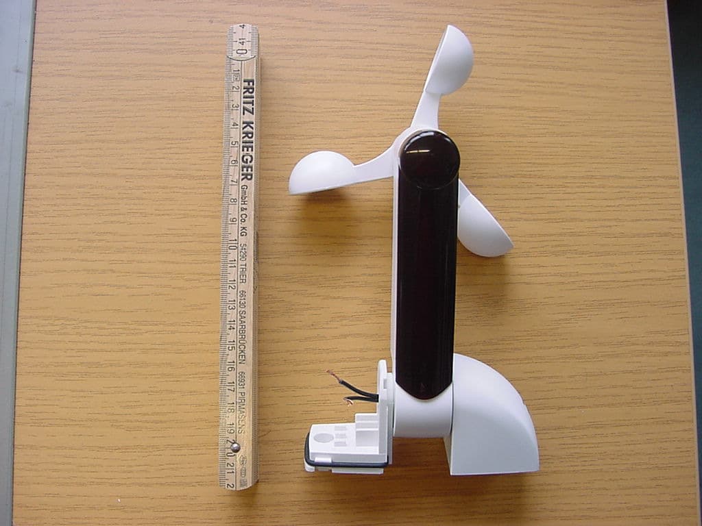
Click to zoom
Application Details
- Equipment Class
- DSC - Part 15 Security/Remote Control Transmitter
- Date of Grant
- Mar 15, 2007
- Application Purpose
- Original Equipment
- Date of Application
- Mar 15, 2007
- Equipment Note
- Climatic sensor
- Frequency Range
- 433.92000000 - 433.92000000
- Company
- Nice S.p.A.
- Country
- Italy
Documents & Files
Document Text
Text extracted from the exhibit documents filed with the FCC. Open a document above to read the original.
Users Manual
Istruzioni ed avvertenze per l’installatore Instructions and warnings for the fitter Instructions et recommandations pour l’installateur Anweisungen und Hinweisefür den Installateur Instrucciones y advertencias para el instalador Instrukcje i uwagi dla instalatora Instructies en waarschuwingen voor de installateur climatic sensor volo s-radio 2 Warnings: For product installation, maintenance and repairs contact only qualified tech- nical personnel, who must comply with the legislation in force. Read the instructions carefully and verify which motors or control units are suitable for use with the VOLO S RADIO weath- er sensor. Any other application is impr oper and pr ohibited. The VOLO S RADIO weather sensor measures WIND speed in Km/h, and the brightness of sunlight in KLux. It can be used to command programmed motors or control units, enabling the automation of awnings, rolling shutters and similar fixtures via a radio control, based on the detected weather conditions. For example, awnings will open automatically when the programmed SUNLIGHT level is exceeded, and will close when the WIND level is exceeded. The commands are sent by radio, therefore the only connections required are the electric line ones (see the “Installation” chapter). VOLO S RADIO is equipped with a programming/transmission button () (Fig. 1, detail B) and a multicoloured indicator light (Led) (Fig. 1, detail C). It also features an audible signal (Beep). 1) Product description 2) Installation Before you install the unit, test the radio range, as the presence of thick walls and/or other devices operating at the same frequency can greatly reduce the range. To check the range, carry out a provisional test (see “Testing” chapter), positioning yourself, first, near the automation and then near the place of final installation. Though the range under favourable conditions, in a free field, can be 100-200 m, taking into account the protection function, we advise you not to exceed 20-30 m. Moreover, you should make sure that there are no other devices operating at the same frequency and with continuous transmission, such as alarms, headphones, etc., which might further reduce the range. For proper operation, keep in mind that the weather sensor must be positioned near the shutter/awning to be protected, in an area that is exposed to the action of the wind and sun. To proceed with the installation, refer to Fig. 2, Fig. 3, Fig. 4 and Fig. 7; remember not to tighten the fastening screw too hard (Fig. 1, detail A). As VOLO S RADIO is supplied with mains voltage, we recom- mend that you do not install it in an easily accessible location. ! 3) Electrical connections The product must be connected to a 230Vac (VOLO S RADIO version) or 120Vac power source (VOLO S RADIO/V1 version), without ground connection, as shown in Fig.5, Fig.6 and Fig.7. After wiring, close the covers on the mounting bracket securely (Fig.1 detail D). ! 1.1) Command rules VOLO S RADIO measures WIND speed and brightness of SUNLIGHT. When the detected value exceeds the programmed level, a command is sent to the motors or control units as described below: Wind:when the WIND level is exceeded for a period of at least 3 sec- onds, an “up” command (corresponding to button ▲on the remote con- trols) is sent. When the threshold value is exceeded, the LED becomes red and while the command is being transmitted, the RED LED flashes. Sun:when the SUN level is exceeded for a period of at least 2 minutes, a “down” command (corresponding to button ▼on the remote controls) is sent. When the threshold value is exceeded, the LED becomes GREEN and while the command is being transmitted, the GREEN LED flashes. Precedence:if both levels are exceeded, precedence is given to WIND before SUN for safety reasons. Only after the WIND level has dropped below the set value for at least 2 minutes, the SUN command is enabled. Each command is repeated at periodic intervals until the SUN/WIND lev- el drops below the set limits. VOLO S RADIO transmits the measured WIND speed in Km/h, bright- ness of SUNLIGHT in Klux, plus RAIN*, TEMPERATURE* and HUMIDI- TY* readings. (*= only for versions with special sensor) 1 GB 3 4) Testing 1.As soon as the control unit is powered, you will hear 4 beeps. 2.The Wind level is indicated by a few RED light flashes. 3.The Sun level is indicated by a few GREEN light flashes. For the correspondence between the number of flashes and the value of the levels see Tables B1 and B2. The following description refers to the use of a motor for awning automation; however, this procedure can also be used for the other applications. To make sure that the sensor has been installed properly, follow the steps listed below. Table “A”Switching on Example 1.As soon as the control unit is powered, you will hear 2 long beeps. “ON”5s 2.Within 5 seconds, press and hold down button ■on the transmitter to be memorized (for about 3 seconds).3s 3.Release button ■when you hear the first of the 3 beeps confirming the memorisation. Note: If the control unit already contains codes, 2 short beeps will be heard when it is switched on. This means that the above procedure is not valid and you will have to proceed as described in Table “A2”. Table “A1”Memorizing the first transmitterExample When the sensor is powered, the following events will take place: -Power ON audible signal (4 Beeps ) -RED light flashes (pre-programmed = 3 ), corresponding to the set WIND level, than GREEN light flashes (pre-programmed = 3 ), corresponding to the set SUN level. 1.Press and hold down button ■on the new transmitter until you hear a beep (after about 5 seconds). New 5s 2.Press slowly 3 times button ■on a previously enabled transmitter (old). Old X3 3.Press button ■on the new transmitter once more. New 4.Finally, 3 beeps will signal that the new transmitter has been correctly memorized. Note: if the memory is full, 6 beeps will indicate that the transmitter cannot be 4.2) Testing the WIND sensor -Position the aw…
Text truncated - open the document above for the full version.
Users Manual
VOLO S RADIO/U IST239.4859 Rev.00 This device complies with Part 15 of the FCC Rules and with RSS-210 of Industry Canada. Operation is subject to the following two conditions: (1) this device my not cause harmful interference, and (2) this device must accept any interference received, including interference that may cause undesired operation. Warning: Changes or modifications made to this equipment not expressly approved by NICE S.p.A. may void the FCC authorization to operate this equipment. This equipment has been tested and found to comply with the limits for a Class B digital device, pursuant to Part 15 of the FCC Rules. These limits are designed to provide reasonable protection against harmful interference in a residential installation. This equipment generates, uses and can radiate radio frequency energy and, if not installed and used in accordance with the instructions, may cause harmful interference to radio communications. However, there is no guarantee that interference will not occur in a particular installation. If this equipment does cause harmful interference to radio or television reception, which can be determined by turning the equipment off and on, the user is encouraged to try to correct the interference by one or more of the following measures: • Reorient or relocate the receiving antenna. • Increase the separation between the equipment and receiver. • Connect the equipment into an outlet on a circuit different from that to which the receiver is connected. • Consult the dealer or an experienced radio/TV technician for help. IMPORTANTE! El presente producto es planeado según las vigentes normativas de los EEUU y CANADA, esta adjunta refiere entonces los datos específicos para tales mercados. Hay que ignorar los mismos valores referidos en el manual de instrucciones VOLO S RADIO. 2) Aunque el alcance en condiciones favorables, campo libre, puede ser de 35-50 m, considerando la función deprotección se recomienda no superar los 7-10 m. También se recomienda controlar que no haya dispositivos que funcionen en la mismafrecuencia tales como alarmas, auriculares con radio, etc. que podrían reducir posteriormente el alcance. 3) El producto debe conectarse a una alimentación a 230 Vca por medio del transformador. 7) Características técnicas Frecuencia de transmisión 433.92 MHz; Potencia irradiada Aprox 0.03 mW (e.r.p.) IMPORTANT! The present product is projected according to the normative be in force in United States and Canada, this addendum brings therefore the specific data for these markets. Ignore the same values brought in the manual of instructions VOLO S RADIO. 2) Though the range under favourable conditions, in a free field, can be 35-50 m, taking into account the protection function, we advise you not to exceed 7-10 m. Moreover, you should make sure that there are no other devices operating at the same frequency, such as alarms, headphones, etc., which might further reduce the range. 3) The product must be connected to 120Vac power source by means transformer. 7) Technical characteristics: Transmission Frequency 433.92 MHz; Radiated Power Approx. 0.03 mW (e.r.p.) IMPORTANT! Le présent produit est conçu selon les norme des USA et CANADA, cet addendum reporte donc les données spécifiques pour ces marchés. Ignorer les mêmes valeurs reportées dans le manuel d'instructions du VOLO S RADIO. 2) Même si la portée dans des conditions favorables en champ libre peut être de 35-50 m, considérant la fonction de protection, il est conseillé de ne pas dépasser 7-10 m. Il est conseillé, en outre, de vérifier qu’il n’y a pas d’autres dispositifs opérant à la même fréquence tels que des alarmes, des écouteurs radio, etc. qui pourraient en réduire ultérieurement la portée. 3) Le produit doit être connecté à une alimentation 120 Vca à l'aide du transformateur. 7) Caractéristiques techniques : Fréquence de transmission 433.92 MHz ; Puissance irradiée environ 0.03 mW (ERP)
Cover Letter(s)
N N i i c c e e S S p p A A V V i i a a P P e e z z z z a a A A l l t t a a , , 1 1 3 3 Z Z . . I I . . R R u u s s t t i i g g n n è è I I - - 3 3 1 1 0 0 4 4 6 6 O O d d e e r r z z o o T T V V I I t t a a l l i i a a P P h h o o n n e e + + 3 3 9 9 . . 0 0 4 4 2 2 2 2 . . 8 8 5 5 3 3 8 8 3 3 8 8 F F a a x x + + 3 3 9 9 . . 0 0 4 4 2 2 2 2 . . 8 8 5 5 3 3 5 5 8 8 5 5 P P . . I I V V A A 0 0 3 3 0 0 9 9 9 9 3 3 6 6 0 0 2 2 6 6 9 9 i i n n f f o o @ @ n n i i c c e e f f o o r r y y o o u u . . c c o o m m w w w w w w . . n n i i c c e e f f o o r r y y o o u u . . c c o o m m CONFIDENTIALITY REQUEST Federal Communication Commission Equipment Authorization Division, Application Processing Branch 7435 Oakland Mills Road Columbia, MD 21048 DATE 14/02/2007 TO WHOM IT MAY CONCERN Pursuant to Paragraphs §0.457 and 0.459 of the Commission’s Rules (47 C.F.R.) and Section §552(b)(4) of the Freedom of Information Act, Company requests confidentiality for the following products: FCC ID Number Product Title/Model PML433VL VOLO S-RADIO/U For the product stated above, we request that the following information be held confidential: 1. Circuit diagrams, BOM, and PCBs submitted as Equipment Authorization Electronic Filing attachment: "schematics”. 2. Block diagram submitted as Equipment Authorization Electronic Filing attachment: “blockdiagram”. 3. Operational description submitted as Equipment Authorization Electronic Filing attachment: “operational description” The above exhibits contain Company trade secrets and proprietary information that could be of benefit to our competitors regarding the design of our mobile handset. This material is not customarily available to the general public and we request that it be withheld from public inspection. If you have any questions, please feel free to contact me at the address shown below. Sincerely, Name: Oscar Marchetto Company: Nice S.p.A. Address: Via Pezza Alta, 13 Z.I. Rustignè I-31046 Oderzo (TV) Phone: +39.0422853838 Email: [email protected]
External Photos
CETECOM ICT Services GmbH Untertürkheimer Str. 6-10, 66117 Saarbruecken Phone: +49 (0) 681 598-0 Fax: -9075 RSC-Laboratory Phone: +49 (0) 681 598-0 Fax: -9075 Test report no.: 2-4237-01-04/06 Date: 2007-01-19 Page 24 of 26 Photo 3 Photo 4
ID Label/Location Info
NICE SPA PAG. 12 di 34 LABEL & LABELING Size: 34x34mm R34mm Colour: White Material: PVC
Internal Photos
CETECOM ICT Services GmbH Untertürkheimer Str. 6-10, 66117 Saarbruecken Phone: +49 (0) 681 598-0 Fax: -9075 RSC-Laboratory Phone: +49 (0) 681 598-0 Fax: -9075 Test report no.: 2-4237-01-04/06 Date: 2007-01-19 Page 25 of 26 Photo 5 Photo 6 CETECOM ICT Services GmbH Untertürkheimer Str. 6-10, 66117 Saarbruecken Phone: +49 (0) 681 598-0 Fax: -9075 RSC-Laboratory Phone: +49 (0) 681 598-0 Fax: -9075 Test report no.: 2-4237-01-04/06 Date: 2007-01-19 Page 26 of 26 Photo 7 Photo 8
Test Report
CETECOM ICT Services GmbH Untertürkheimer Str. 6-10, 66117 Saarbruecken Phone: +49 (0) 681 598-0 Fax: -9075 RSC-Laboratory Phone: +49 (0) 681 598-0 Fax: -9075 Test report no.: 2-4237-01-04/06 Date: 2007-01-19 Page 1 of 26 Recognized by the Federal Communications Commission Anechoic chamber registration no.: 90462 (FCC) Anechoic chamber registration no.: 3463A-1 (IC) TCB ID: DE 0001 Accredited by the German Accreditation Council DAR–Registration Number DAT-P-176/94-D1 Independent ETSI compliance test house ETSI Accredited Bluetooth ® Test Facility (BQTF) Test report no. : 2-4237-01-04/06 Applicant : Nice S.p.a. Type : VOLO S RADIO/U Test Standard : FCC Part 15 / RSS210 Issue 6 FCC ID : PML433VL Certification No. IC : 6140A-433VL The Bluetooth word mark and logos are owned by the Bluetooth SIG, Inc. and any use of such marks by Cetecom ICT is under license CETECOM ICT Services GmbH Untertürkheimer Str. 6-10, 66117 Saarbruecken Phone: +49 (0) 681 598-0 Fax: -9075 RSC-Laboratory Phone: +49 (0) 681 598-0 Fax: -9075 Test report no.: 2-4237-01-04/06 Date: 2007-01-19 Page 2 of 26 Table of contents 1 GENERAL INFORMATION ................................................................................................................................... 3 1.1. ADMINISTRATIVE DATA OF THE TEST FACILITY..................................................................................................... 3 1.1.1 Identification of the testing laboratory ......................................................................................................... 3 1.2. NOTES................................................................................................................................................................... 3 1.3 DETAILS OF APPLICANT......................................................................................................................................... 4 1.4 APPLICATION DETAILS.......................................................................................................................................... 4 1.5 TEST ITEM............................................................................................................................................................. 5 1.6 TEST SETUP........................................................................................................................................................... 6 1.7 TEST SPECIFICATIONS............................................................................................................................................ 6 2 STATEMENT OF COMPLIANCE .......................................................................................................................... 6 2.1 SUMMARY OF MEASUREMENT RESULTS................................................................................................................ 6 2.1.1 CFR 47 Part 15 Radio frequency devices ..................................................................................................... 6 3 MEASUREMENTS AND RESULTS ....................................................................................................................... 7 4 FCC PART 15 SUBPART C...................................................................................................................................... 8 4.1 Timing of the transmitter .................................................................................................................................. 8 4.2 Field strength of the fundamental ..................................................................................................................... 9 4.3 Field strength of the harmonics and the spurious........................................................................................... 10 4.4 Plots of measurements ....................................................................................................................................11 4.5 Receiver spurious emission (radiated)............................................................................................................ 14 4.6 Conducted Limits ............................................................................................................................................ 15 5 ANNEX B: PHOTOGRAPHS OF TEST SITE ..................................................................................................... 20 6 ANNEX C: PHOTOGRAPHS OF EUT ................................................................................................................ 23 CETECOM ICT Services GmbH Untertürkheimer Str. 6-10, 66117 Saarbruecken Phone: +49 (0) 681 598-0 Fax: -9075 RSC-Laboratory Phone: +49 (0) 681 598-0 Fax: -9075 Test report no.: 2-4237-01-04/06 Date: 2007-01-19 Page 3 of 26 1 General information 1.1. Administrative data of the test facility 1.1.1 Identification of the testing laboratory Company name: Cetecom ICT Services GmbH Address: Untertürkheimerstr. 6-10 D-66117 Saarbruecken Germany Laboratory accreditation: DAR-Registration No. DAT-P-176/94-D1 Bluetooth Qualification Test Facility (BQTF) Federal Communications Commission (FCC) Identification/Registration No : 90462 Responsible for testing laboratory: Michael Berg Phone: +49 681 598 0 Fax: +49 681 598 9075 email: [email protected] 1.2. Notes The test results of this test report relate exclusively to the test item specified in 1.5. The CETECOM ICT Services GmbH does not assume responsibility for any conclusions and generalizations drawn from the test results with regard to other specimens or samples of the type of the equipment represented by the test item. The test report may only be reproduced or published in full. Reproduction or publication of extracts from the report requires the prior written approval of the CETECOM ICT Services GmbH. .................................................................................. Responsible for testing (D. Gillmann) ........................................…
Text truncated - open the document above for the full version.
Test Setup Photos
CETECOM ICT Services GmbH Untertürkheimer Str. 6-10, 66117 Saarbruecken Phone: +49 (0) 681 598-0 Fax: -9075 RSC-Laboratory Phone: +49 (0) 681 598-0 Fax: -9075 Test report no.: 2-4237-01-04/06 Date: 2007-01-19 Page 20 of 26 5 Annex B: Photographs of Test site Photo 1 (Radiated Emissions): Photo 2 (Radiated Emissions): CETECOM ICT Services GmbH Untertürkheimer Str. 6-10, 66117 Saarbruecken Phone: +49 (0) 681 598-0 Fax: -9075 RSC-Laboratory Phone: +49 (0) 681 598-0 Fax: -9075 Test report no.: 2-4237-01-04/06 Date: 2007-01-19 Page 21 of 26 Photo 3 (Radiated Emissions): Photo 4 (Radiated Emissions): CETECOM ICT Services GmbH Untertürkheimer Str. 6-10, 66117 Saarbruecken Phone: +49 (0) 681 598-0 Fax: -9075 RSC-Laboratory Phone: +49 (0) 681 598-0 Fax: -9075 Test report no.: 2-4237-01-04/06 Date: 2007-01-19 Page 22 of 26 Photo 4 (Conducted Emissions): CETECOM ICT Services GmbH Untertürkheimer Str. 6-10, 66117 Saarbruecken Phone: +49 (0) 681 598-0 Fax: -9075 RSC-Laboratory Phone: +49 (0) 681 598-0 Fax: -9075 Test report no.: 2-4237-01-04/06 Date: 2007-01-19 Page 23 of 26 6 Annex C: Photographs of EUT Photo 1 ‚ Photo 2
Contact Information
Applicant
Enrico Campion(Laboratory Manager)
Test Firm
cetecom advanced GmbHGerald Schmidt
Technical Specifications
| # | Rule Parts | Frequency Range | Power Output |
|---|---|---|---|
| 1 | 15.231 | 433.92 MHz - 433.92 MHz | - |
Other Applications from Nice S.p.A.
PMLILIONBD
May 26, 2026Tubular Motor
Equipment Class
DSC - Part 15 Security/Remote Control Transmitter
PMLDOMIP18
Sep 29, 2025Handheld TX
Equipment Class
DSR - Part 15 Remote Control/Security Device Transceiver
PMLMYGOA
May 03, 2022Transceiver Control
Equipment Class
DSR - Part 15 Remote Control/Security Device Transceiver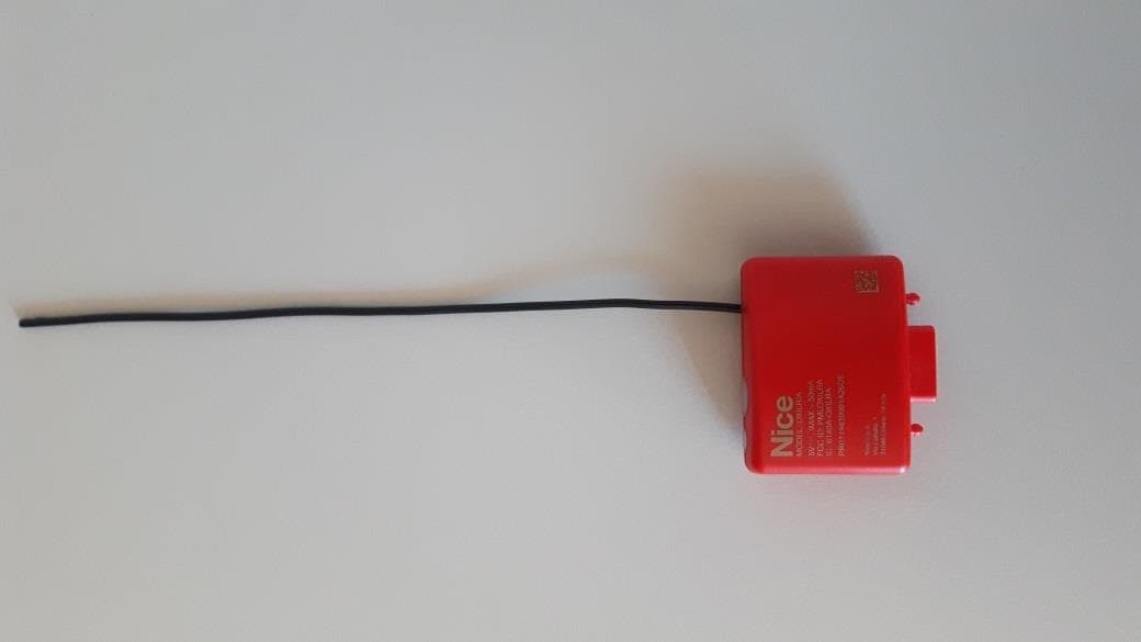
PMLOXILRA
Jun 30, 2020Transceiver control
Equipment Class
DTS - Digital Transmission System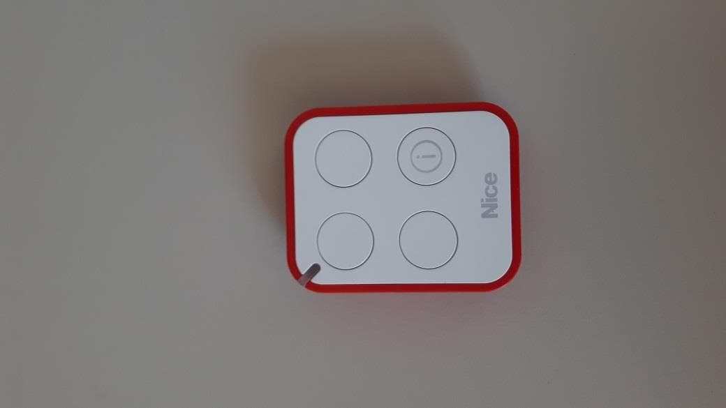
PMLON3ELRA
Jun 30, 2020Transceiver control
Equipment Class
DTS - Digital Transmission System