PMLERAPRemote Control
Nice S.p.A.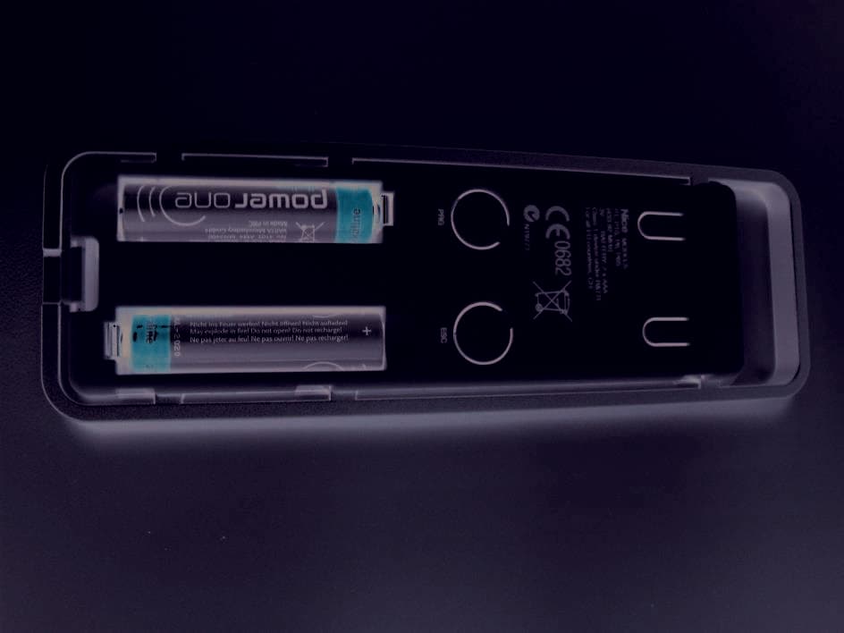
Click to zoom
Application Details
- Equipment Class
- DSC - Part 15 Security/Remote Control Transmitter
- Date of Grant
- Aug 27, 2014
- Application Purpose
- Original Equipment
- Date of Application
- Aug 27, 2014
- Equipment Note
- Remote Control
- Frequency Range
- 433.92000000 - 433.92000000
- Company
- Nice S.p.A.
- Country
- Italy
Documents & Files
Document Text
Text extracted from the exhibit documents filed with the FCC. Open a document above to read the original.
Users Manual
PRODUCT DESCRIPTION AND INTENDED USE This transmitter is part of the “Era-P” / “Era-W” Nice range. The transmitters of these two ranges are used to control automation mechanisms for aw- nings, outdoor sunblinds or blinds: any other use is improper and forbidden! Functional specifications • The “Era-P” range consists of portable mod- els (“P”) while the “Era-W” range consists of wall mounted models (“W”). • 1 or 6 “unit” models are available to send commands to, as well as models with commands for the management of the weather sensors. • Some models are provided with a hook to temporarily hang the transmitter on the wall, oth- ers are provided with a plate to mount it on the wall. To install this accessory please refer to fig. 2 or 3. • Fig. 1 reports all the keys which may be on the transmitters, based on the model. Their use is as follows: A - “Unit” keys (only in the P6/U, P6S/U, W6/U, W6S/U models): are required to select the automation mechanism/s to send the com- mands to. While memorising the transmitter, it is necessary to programme at least one of these keys, associating at least one automa- tion mechanism/s to them. This makes the key a “unit for the reception of the commands”, meaning that the automation mechanisms as- sociated to it will receive the same commands during the use of the transmitter. The other keys available may be programmed in a similar manner, based on the system’s needs. For all purposes, it is like having 6 independent trans- mitters in a single command device. B - Command keys (in all the models): are re- quired to send the rise (▲), stop (■) and lower (▼) commands. In the P6/U, P6S/U, W6/U, W6S/U models, prior to sending a command, select the “unit” to send the command to. C - Control keys of the automatic commands (only in the P1S/U, P6S/U, W1S/U, W6S/U models): the key enables (the key dis- ables) the reception by the motor of the auto- matic commands transmitted by any weather sensor in the installation. When is pressed the system sets the automatic operating mode of the automation mechanism whereas when is pressed the system sets the manual operating mode of the automation mecha- nism. The “Wind” sensor may not be disabled since it is required to protect the automation mechanism from wind damage. With the auto- matic operating mode enabled, the user may send manual commands any time. For more information please refer to the manual of the automation mechanism and the weather sen- sor. D - Programming keys (in all the models): in the compatible motors (e.g. those of the Era Mat range), these keys are required to simplify the performance of the programming procedures: the PRG key speeds up the access to the pro- cedures, whereas the ESC key speeds up the exit from them. To access the keys remove the battery cover. In the P6/U, P6S/U, W6/U, W6S/U models: during the execution of the procedures, when pressing these keys is required, it is necessary to firstly select the single “unit” where the pro- cedure is being performed. TESTING THE TRANSMITTER Before memorising the transmitter in the receiver of the motor, check its proper operation by pressing any key and observing whether the LED lights up (fig. 1-E). If it does not, refer to the section entitled “Replacing the Battery” in this manual. SPECIFIC FUNCTIONS OF THE TRANSMITTER • Select a “unit” to send a command to (only for the P6/U, P6S/U, W6/U, W6S/U models) With these transmitter models, prior to sending a command it is necessary to select the “unit” (i.e. the automation mechanisms associated to this) to send the command to. After selecting the unit, its LED remains lit for a few seconds and, before its turns off, it is possible to select other units to be added to the first selected (to eliminate a unit selected by mistake, turn off its LED by briefly pressing the as- sociated key). After selecting the units desired, when their LEDs automatically turn off, the units will remain in the transmitter’s memory until a new unit/s is/are se- lected. While they remain in the memory it will be possible to send them commands without having to select them first. • Enable or disable the reception of the auto- matic commands sent from a weather sen- sor (only for the P1S/U, P6S/U, W1S, W6S/U models) With these transmitter models it is possible to en- able or disable the reception of the automatic com- mands coming from any weather sensor connected (e.g. the “Sun” automatism mechanisms). For a good management of the automation mechanisms connected to the weather sensors, we advise using a single transmitter provided with keys to enable or disable automatic commands. Only for the P6S/U and W6S/U models: in these transmitters, prior to enabling or disabling the op- erating mode, it is necessary to select the “unit/s” which the setting must be sent to. While using these transmitters, to check whether the units are enabled or disabled, just select these one at a time and ob- serve the state of the LEDs: lit; off = function enabled; off; lit = function disabled; Note – If more units are selected and the two LEDs appear to be off, this means that there is at least one unit which has the automatic commands enabled. MEMORISING THE TRANSMITTER To memorise the transmitter in a control unit (or in a receiver) it is possible to choose one of the following procedures, compatibly with the presence of this in the manual of the control unit or the receiver: A - Memorisation in “Mode I” B - Memorisation in “Mode II” C - Memorisation of a new transmitter through another already memorised The detailed instructions of each procedure are reported in the instruction manual of the motor or the control unit with which you want to make the transmitter work. These manuals are also available in the website: www.niceforyou.com. Since in the manuals the transmitter keys may be identified with symbols or numbers, please refer to fig. 1-B to know the correspondence between these and the transmitter keys. A - Memorisation in “Mode I” This mode a…
Text truncated - open the document above for the full version.
Block Diagram
NICE SPA PAG. 6 Technical schemes All the models Loop Antenna Antenna Filter Q3, SAW1 433.92 MHz oscillator IC1 Encoder To Q3, IC1 3VCC Battery P1..P13 Buttons Internal oscillator 8MHz
Cover Letter(s)
N N i i c c e e S S p p A A V V i i a a P P e e z z z z a a A A l l t t a a , , 1 1 3 3 Z Z . . I I . . R R u u s s t t i i g g n n è è I I - - 3 3 1 1 0 0 4 4 6 6 O O d d e e r r z z o o T T V V I I t t a a l l i i a a C C a a p p . . S S o o c c . . € € 1 1 1 1 . . 6 6 0 0 0 0 . . 0 0 0 0 0 0 i i . . v v . . P P h h o o n n e e + + 3 3 9 9 . . 0 0 4 4 2 2 2 2 . . 8 8 5 5 3 3 8 8 3 3 8 8 F F a a x x + + 3 3 9 9 . . 0 0 4 4 2 2 2 2 . . 8 8 5 5 3 3 5 5 8 8 5 5 P P . . I I V V A A 0 0 3 3 0 0 9 9 9 9 3 3 6 6 0 0 2 2 6 6 9 9 i i n n f f o o @ @ n n i i c c e e f f o o r r y y o o u u . . c c o o m m w w w w w w . . n n i i c c e e f f o o r r y y o o u u . . c c o o m m 022311 – 6 Authority to Act as Agent Date: 2014-06-30 American Certification Body, Inc. 6731 Whittier Avenue Suite C110 McLean, VA 22101 To Whom It May Concern: _______IMQ S.p.A is authorized to act on our behalf, until otherwise notified, for applications to American Certification Body, Inc. (ACB). We certify that we are not subject to denial of federal benefits, that includes FCC benefits, pursuant to Section 5301 of the Anti-Drug Abuse Act of 1988, 21 U.S.C. 862. Further, no party, as defined in 47 CFR 1.2002 (b), to the application is subject to denial of federal benefits, that includes FCC benefits. Thank you, Agency Agreement Expiration Date: _____12 months (Typically 8 – 12 months)_____ By: ____________________ __ Mr. Enrico Campion ____________ (Signature 1 ) (Print name) Title: __ Laboratory Manager______________ On behalf of: __ Nice S.p.A._____________ (Company Name) Telephone: _ +39 0422 853838 ____ 1 - Must be signed by applicant contact given for applicant on the FCC site, or by the authorized agent if an appropriate authorized agent letter has been provided. Letters should be placed on appropriate letterhead. N N i i c c e e S S p p A A V V i i a a P P e e z z z z a a A A l l t t a a , , 1 1 3 3 Z Z . . I I . . R R u u s s t t i i g g n n è è I I - - 3 3 1 1 0 0 4 4 6 6 O O d d e e r r z z o o T T V V I I t t a a l l i i a a C C a a p p . . S S o o c c . . € € 1 1 1 1 . . 6 6 0 0 0 0 . . 0 0 0 0 0 0 i i . . v v . . P P h h o o n n e e + + 3 3 9 9 . . 0 0 4 4 2 2 2 2 . . 8 8 5 5 3 3 8 8 3 3 8 8 F F a a x x + + 3 3 9 9 . . 0 0 4 4 2 2 2 2 . . 8 8 5 5 3 3 5 5 8 8 5 5 P P . . I I V V A A 0 0 3 3 0 0 9 9 9 9 3 3 6 6 0 0 2 2 6 6 9 9 i i n n f f o o @ @ n n i i c c e e f f o o r r y y o o u u . . c c o o m m w w w w w w . . n n i i c c e e f f o o r r y y o o u u . . c c o o m m 022311 – 6 Request for Confidentiality Date: 2014-06-30 Subject: Confidentiality Request for: ____PMLERAP_____ Pursuant to FCC 47 CRF 0.457(d) and 0.459 and IC RSP-100, Section 10, the applicant requests that a part of the subject FCC application be held confidential. Type of Confidentiality Requested Exhibit Short Term Permanent Block Diagrams Short Term External Photos Short Term Permanent* 2 Internal Photos Short Term Permanent Operation Description/Theory of Operation Short Term Permanent Parts List & Placement/BOM Short Term Permanent Tune-Up Procedure Short Term Permanent Schematics Short Term Test Setup Photos Short Term Permanent* User’s Manual *Note: ___Description: Remote Control___(Insert Explanation as Necessary)______ ______ Nice S.p.A. ______ has spent substantial effort in developing this product and it is one of the first of its kind in industry. Having the subject information easily available to "competition" would negate the advantage they have achieved by developing this product. Not protecting the details of the design will result in financial hardship. Permanent Confidentiality: The applicant requests the exhibits listed above as permanently confidential be permanently withheld from public review due to materials that contain trade secrets and proprietary information not customarily released to the public. Short-Term Confidentiality: The applicant requests the exhibits selected above as short term confidential be withheld from public view for a period of _180__(specify number of days not to exceed 180) 3 ___ days from the date of the Grant of Equipment Authorization and prior to marketing. This is to avoid premature release of sensitive information prior to marketing or release of the product to the public. Applicant is also aware that they are responsible to notify ACB in the event information regarding the product or the product is made available to the public. ACB will then release the documents listed above for public disclosure pursuant to FCC Public Notice DA 04-1705. NOTE for Industry Canada Applications: The applicant understands that until such time that IC distinguishes between Short Term and Permanent Confidentiality, either type of marked exhibit above will simply be marked Confidential when submitted to IC. Sincerely, By: ______ ____________________ _______Mr. Enrico Campion ____ (Signature/Title 4 ) (Print name) 2 - The asterisked items (*) require further justification before permanent confidentiality will be allowed. These also currently require review by the FCC under their Permit-But-Ask policy before the grant is issued and can delay completion of an application. Further justification should be added to the note above. One such example for a potted device would be: “The EUT is FULLY potted using a non-removable epoxy based material. Removal of potting material causes irreparable damage to internal circuitry. See photographs exhibits that outline the device before and after potting.” 3 - Please refer to http://acbcert.com/documents/misc-docs/Memo-Short-Term-Vs-Standard-Confidentiality.pdf for complete details. 4 - Must be signed by applicant contact given for applicant on the FCC site, or by the authorized agent if an appropriate N N i i c c e e S S p p A A V V i i a a P P e e z z z z a a A A l l t t a a , , 1 1 3 3 Z Z . . I I . . R R u u s s t t i i g g n n è è I I - - 3 3 1 1 0 0 4 4 6 6 O O d d e e r r z z o o T T V V I I t t a a l l i i a a C C a a p p . . S S o o c c . . € € 1 1 1 1 . . 6 6 0 0 0 0…
Text truncated - open the document above for the full version.
Cover Letter(s)
N N i i c c e e S S p p A A V V i i a a P P e e z z z z a a A A l l t t a a , , 1 1 3 3 Z Z . . I I . . R R u u s s t t i i g g n n è è I I - - 3 3 1 1 0 0 4 4 6 6 O O d d e e r r z z o o T T V V I I t t a a l l i i a a C C a a p p . . S S o o c c . . € € 1 1 1 1 . . 6 6 0 0 0 0 . . 0 0 0 0 0 0 i i . . v v . . P P h h o o n n e e + + 3 3 9 9 . . 0 0 4 4 2 2 2 2 . . 8 8 5 5 3 3 8 8 3 3 8 8 F F a a x x + + 3 3 9 9 . . 0 0 4 4 2 2 2 2 . . 8 8 5 5 3 3 5 5 8 8 5 5 P P . . I I V V A A 0 0 3 3 0 0 9 9 9 9 3 3 6 6 0 0 2 2 6 6 9 9 i i n n f f o o @ @ n n i i c c e e f f o o r r y y o o u u . . c c o o m m w w w w w w . . n n i i c c e e f f o o r r y y o o u u . . c c o o m m Description of variants of product Date: 2014-08-08 Subject: Description of variants of products (FCC ID: PMLERAP) I confirm that the four variants of remote control (FCC IF: PMLERAP) have identical internal circuitry. The schematic is same for all version of remote control. The version P6S has all buttons and versions P1, P1S and P6 have same schematic but without some buttons. Sincerely, By: ______ ____________________ _______Mr. Enrico Campion ____
External Photos
FCC test report Report nr. 0241aFCC1 page 31 / 38 date: 2014-06-30 Nice S.p.A. Oderzo TV Italia tel. +39.0422.853838 www.niceforyou.com 7 Photographic Documentation 8.1 EUT Identification FCC test report Report nr. 0241aFCC1 page 32 / 38 date: 2014-06-30 Nice S.p.A. Oderzo TV Italia tel. +39.0422.853838 www.niceforyou.com FCC test report Report nr. 0241aFCC1 page 33 / 38 date: 2014-06-30 Nice S.p.A. Oderzo TV Italia tel. +39.0422.853838 www.niceforyou.com
ID Label/Location Info
MODEL: P1/U 3V , BATTERY: 2 x AAA FCC ID: PMLERAP IC. 6140A-ERAP
ID Label/Location Info
N N i i c c e e S S p p A A V V i i a a P P e e z z z z a a A A l l t t a a , , 1 1 3 3 Z Z . . I I . . R R u u s s t t i i g g n n è è I I - - 3 3 1 1 0 0 4 4 6 6 O O d d e e r r z z o o T T V V I I t t a a l l i i a a C C a a p p . . S S o o c c . . € € 1 1 1 1 . . 6 6 0 0 0 0 . . 0 0 0 0 0 0 i i . . v v . . P P h h o o n n e e + + 3 3 9 9 . . 0 0 4 4 2 2 2 2 . . 8 8 5 5 3 3 8 8 3 3 8 8 F F a a x x + + 3 3 9 9 . . 0 0 4 4 2 2 2 2 . . 8 8 5 5 3 3 5 5 8 8 5 5 P P . . I I V V A A 0 0 3 3 0 0 9 9 9 9 3 3 6 6 0 0 2 2 6 6 9 9 i i n n f f o o @ @ n n i i c c e e f f o o r r y y o o u u . . c c o o m m w w w w w w . . n n i i c c e e f f o o r r y y o o u u . . c c o o m m Declaration for Shipping Date: 2014-08-08 Subject: Declaration for shipping (FCC ID: PMLERAP, IC: 6140A-ERAP) Nice S.p.A. DECLARE That the products P1/U, P1S/U, P6/U, P6S/U (FCC IF: PMLERAP and IC: 6140A-ERAP) will be shipped to the user with the battery cover removed. Sincerely, By: __________________________ _______Mr. Enrico Campion ____
Internal Photos
FCC test report Report nr. 0241aFCC1 page 34 / 38 date: 2014-06-30 Nice S.p.A. Oderzo TV Italia tel. +39.0422.853838 www.niceforyou.com FCC test report Report nr. 0241aFCC1 page 35 / 38 date: 2014-06-30 Nice S.p.A. Oderzo TV Italia tel. +39.0422.853838 www.niceforyou.com
Operational Description
NICE SPA PAG. 3 Overview Transmitters allow you to manage 1 group or 6 group of automation, with or without control of climate sensor. Every group is formed by three different channel. By channel we mean a different code and not different frequency bands. All models have exactly the same circuit while the number of push buttons. They are powered by two 1.5V-alkaline battery AAA (included ). Description of the product All the transmitters The circuit consists of: -The Q3 transistor that works like an oscillator; the signal taken from its collector passes through the C15-L2– C18 filter and reaches the Loop type aerial, engraved on a printed circuit, providing a guarantee of stability as regards its characteristics and, consequently, the complete lack of calibrations. The SAW1 Resonator guarantees the exact oscillation frequency. -The code is generated by the integrated circuit IC1 and consists of a train of 74 pulses lasting 114 ms followed by a pause of another 18 ms; as the code is the "Rolling Code" type, it changes each time the push button on the remote control is pressed. NICE SPA PAG. 4 Technical specifications Transmitters Working temperature: from -10°C to +55°C Center frequency: 433.92 MHz ± 100KHz Modulation: AM-OOK wide band Duty Cycle in 100 ms calculation (worst case): Code: A train of 74 pulses lasting 114 ms followed by a pause of 18ms. TOTAL PERIOD : T = 132 ms FRAME PERIOD : T F = 114 ms PAUSE : T P = 18ms START BIT : T S = 1.5 ms SINGLE BIT : T BIT = 1.5ms IMPULSE TYPE “0” : T ON = 0.5 ms, T OFF = 1.0 ms IMPULSE TYPE “1” : T ON = 1.0 ms, T OFF = 0.5 ms STOP BIT : TFs = 1.5 ms Then the 100 ms worst case (WC) is DC = ON TIME WC / 100 ms = ((1.5 + 1* 65 )/100) = 0.665 20 LOG(DC) = - 3.5 dB ( correction factor) Stop Bit Start Bit T S T P T F T T BIT T ON “0” T OFF “1” T OFF T ON T BIT
Test Report
FCC test report Notice: The result of tests and checks reported in this Test Report refer exclusively to the samples tested and described in the Report itself. This report shall not be reproduced partially or in its entirely without written approval of Nice S.p.A. Report nr. 0241aFCC1 page 1 / 38 date: 2014-06-30 Nice S.p.A. Oderzo TV Italia tel. +39.0422.853838 www.niceforyou.com Test report nr. 0241aFCC14 Measurements performed in accordance with: FCC Rules: code of Federal Regulations (CFR) no. 47 PART 15 – RADIO FREQUENCY DEVICES Product: Remote control (modified the product) Tested model: P1/U, P1S/U, P6, P6S/U FCC ID PMLERAP Applicant: Nice S.p.A. Manufacturer: Nice S.p.A. Trademark: Nice Testing Laboratory Nice S.p.A. Via Pezza Alta, 13 I-31046 Rustignè di Oderzo (TV) Registration number: 771316 Date of receipt sample: 2014-05-09 Testing date: 2014-05-09 to 15-05-2014 Issue date: 2014-06-30 Tested by: L. Pastres Checked by: E. Campion FCC test report Report nr. 0241aFCC1 page 2 / 38 date: 2014-06-30 Nice S.p.A. Oderzo TV Italia tel. +39.0422.853838 www.niceforyou.com Contents Contents ............................................................................................................................. 2 1 General Description of Equipment under Test ............................................................. 3 1.1 Applicant .................................................................................................................... 3 1.2 Manufacturer .............................................................................................................. 3 1.3 Equipment classification ............................................................................................. 3 1.4 Basic Description of equipment under test ................................................................. 4 1.5 Feature of equipment under test ................................................................................ 5 2 Test configuration of equipment under test ................................................................. 6 2.1 Environmental conditions ........................................................................................... 6 2.2 Description of support equipment............................................................................... 6 2.3 Interface identification and connection diagram of test system .................................. 7 3 Operation of equipment under test ............................................................................... 8 3.1 Operating test conditions ........................................................................................... 8 4 Tests identification and result ....................................................................................... 9 4.1 Methods of measurement .......................................................................................... 9 4.2 Frequency range investigated .................................................................................... 9 5 Tests .............................................................................................................................. 10 5.1 Radiated emission .................................................................................................... 10 5.2 Timing of the transmitter .......................................................................................... 14 5.3 Transmit behaviour after releasing the TX-button .................................................... 17 5.4 Radiated output power ............................................................................................. 18 5.5 Typical pulse train of a signal ................................................................................... 21 5.6 Compliance with the limit of FCC ............................................................................. 22 5.7 Spurious emission - radiated .................................................................................... 23 5.8 Occuped bandwith ................................................................................................... 26 6 Measurement and Test Equipment instrumentation.................................................. 27 7 Photographic Documentation ...................................................................................... 31 8.1 EUT Identification ..................................................................................................... 31 8.2 Test Set-up .............................................................................................................. 36 Annex 1 Site Validation .................................................................................................. 38 FCC test report Report nr. 0241aFCC1 page 3 / 38 date: 2014-06-30 Nice S.p.A. Oderzo TV Italia tel. +39.0422.853838 www.niceforyou.com 1 General Description of Equipment under Test 1.1 Applicant Name: Nice S.p.A. Address: via Pezza Alta, 13 Country: 31046 Rustignè di Oderzo (TV) – Italy 1.2 Manufacturer Name: Nice S.p.A. Address: via Pezza Alta, 13 Country: 31046 Rustignè di Oderzo (TV) – Italy 1.3 Equipment classification According to definition 15.3 (o) is a intentional Radiator operating within the Bands: so it shall fulfil provisions of 47CFR Part 15 Subpart C – international radiators – and Section 15.209. According to definition 15.3 (z) is a unintentional Radiator: So it shall fulfil provisions of 47CFR Part 15 Subpart B – Unintentional radiator and section 15.107 and 15.109. FCC test report Report nr. 0241aFCC1 page 4 / 38 date: 2014-06-30 Nice S.p.A. Oderzo TV Italia tel. +39.0422.853838 www.niceforyou.com 1.4 Basic Description of equipment under test Parameters Value Type of equipment: LPD transmitter Model: P1/U, P1S/U, P6/U, P6S/U FCC ID: PMLERAP Trade Name: Nice Data cable: - Telecom cable: - Power supply type: internal battery AC power input cable: - DC power input cable: 3Vdc with internal battery 2 x type AAA Model Descri…
Text truncated - open the document above for the full version.
Test Setup Photos
FCC test report Report nr. 0241aFCC1 page 36 / 38 date: 2014-06-30 Nice S.p.A. Oderzo TV Italia tel. +39.0422.853838 www.niceforyou.com 8.2 Test Set-up FCC test report Report nr. 0241aFCC1 page 37 / 38 date: 2014-06-30 Nice S.p.A. Oderzo TV Italia tel. +39.0422.853838 www.niceforyou.com
Contact Information
Applicant
Enrico Campion(Laboratory Manager)
Non-Technical Contact
Nice S.p.A.Enrico Campion
Test Firm
NICE S.p.A.Enrico Campion
Technical Specifications
| # | Rule Parts | Frequency Range | Power Output |
|---|---|---|---|
| 1 | 15.231 | 433.92 MHz - 433.92 MHz | - |
Other Applications from Nice S.p.A.
PMLILIONBD
May 26, 2026Tubular Motor
Equipment Class
DSC - Part 15 Security/Remote Control Transmitter
PMLDOMIP18
Sep 29, 2025Handheld TX
Equipment Class
DSR - Part 15 Remote Control/Security Device Transceiver
PMLMYGOA
May 03, 2022Transceiver Control
Equipment Class
DSR - Part 15 Remote Control/Security Device Transceiver
PMLOXILRA
Jun 30, 2020Transceiver control
Equipment Class
DTS - Digital Transmission System
PMLON3ELRA
Jun 30, 2020Transceiver control
Equipment Class
DTS - Digital Transmission System